2008 NISSAN TEANA engine oil
[x] Cancel search: engine oilPage 3206 of 5121
MA-18
< ON-VEHICLE MAINTENANCE >
ENGINE MAINTENANCE
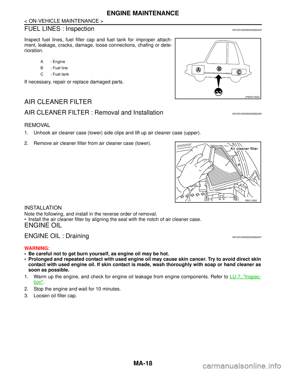
FUEL LINES : Inspection
INFOID:0000000003862455
Inspect fuel lines, fuel filler cap and fuel tank for improper attach-
ment, leakage, cracks, damage, loose connections, chafing or dete-
rioration.
If necessary, repair or replace damaged parts.
AIR CLEANER FILTER
AIR CLEANER FILTER : Removal and InstallationINFOID:0000000003862456
REMOVAL
1. Unhook air cleaner case (lower) side clips and lift up air cleaner case (upper).
2. Remove air cleaner filter from air cleaner case (lower).
INSTALLATION
Note the following, and install in the reverse order of removal.
Install the air cleaner filter by aligning the seal with the notch of air cleaner case.
ENGINE OIL
ENGINE OIL : DrainingINFOID:0000000003862457
WARNING:
Be careful not to get burn yourself, as engine oil may be hot.
Prolonged and repeated contact with used engine oil may cause skin cancer. Try to avoid direct skin
contact with used engine oil. If skin contact is made, wash thoroughly with soap or hand cleaner as
soon as possible.
1. Warm up the engine, and check for engine oil leakage from engine components. Refer to LU-7, "
Inspec-
tion".
2. Stop the engine and wait for 10 minutes.
3. Loosen oil filler cap.
A : Engine
B : Fuel line
C: Fuel tank
JPBIA0129ZZ
PBIC1165E
Page 3207 of 5121
ENGINE MAINTENANCE
MA-19
< ON-VEHICLE MAINTENANCE >
C
D
E
F
G
H
I
J
K
L
MB
MAN
OA
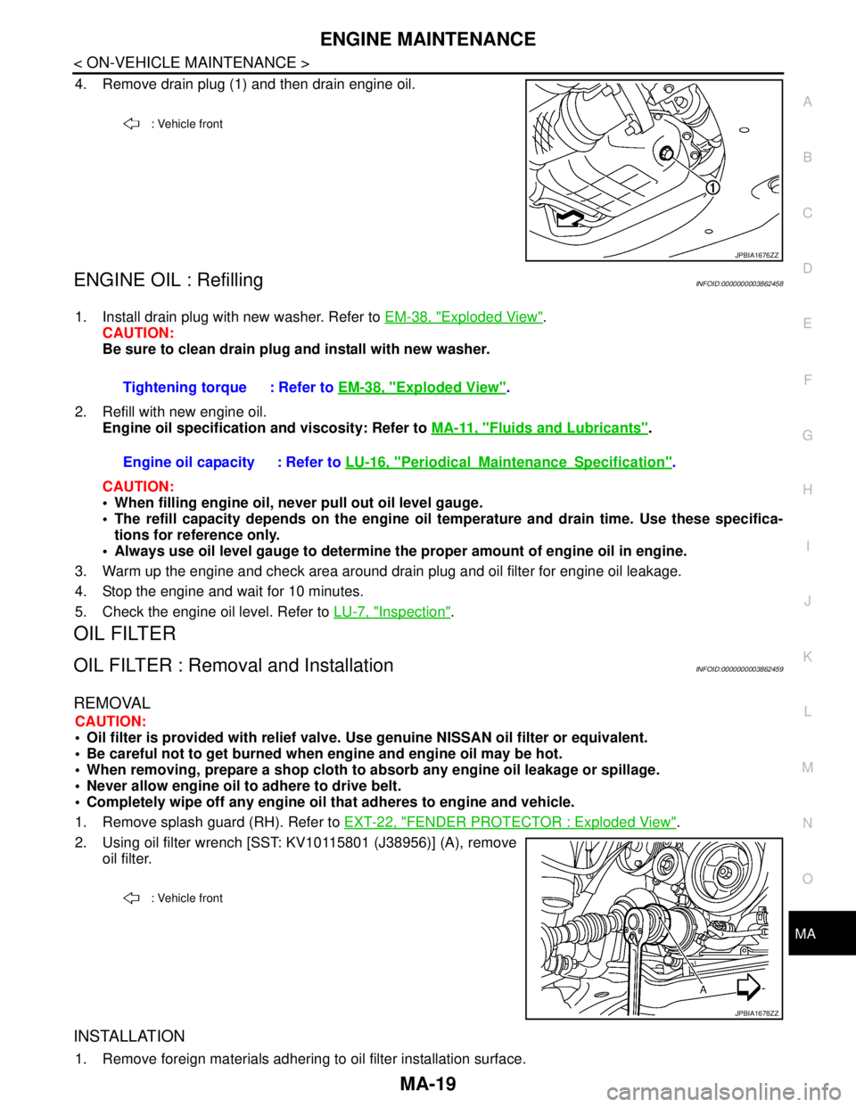
4. Remove drain plug (1) and then drain engine oil.
ENGINE OIL : RefillingINFOID:0000000003862458
1. Install drain plug with new washer. Refer to EM-38, "Exploded View".
CAUTION:
Be sure to clean drain plug and install with new washer.
2. Refill with new engine oil.
Engine oil specification and viscosity: Refer to MA-11, "
Fluids and Lubricants".
CAUTION:
When filling engine oil, never pull out oil level gauge.
The refill capacity depends on the engine oil temperature and drain time. Use these specifica-
tions for reference only.
Always use oil level gauge to determine the proper amount of engine oil in engine.
3. Warm up the engine and check area around drain plug and oil filter for engine oil leakage.
4. Stop the engine and wait for 10 minutes.
5. Check the engine oil level. Refer to LU-7, "
Inspection".
OIL FILTER
OIL FILTER : Removal and InstallationINFOID:0000000003862459
REMOVAL
CAUTION:
Oil filter is provided with relief valve. Use genuine NISSAN oil filter or equivalent.
Be careful not to get burned when engine and engine oil may be hot.
When removing, prepare a shop cloth to absorb any engine oil leakage or spillage.
Never allow engine oil to adhere to drive belt.
Completely wipe off any engine oil that adheres to engine and vehicle.
1. Remove splash guard (RH). Refer to EXT-22, "
FENDER PROTECTOR : Exploded View".
2. Using oil filter wrench [SST: KV10115801 (J38956)] (A), remove
oil filter.
INSTALLATION
1. Remove foreign materials adhering to oil filter installation surface.
: Vehicle front
JPBIA1676ZZ
Tightening torque : Refer to EM-38, "Exploded View".
Engine oil capacity : Refer to LU-16, "
PeriodicalMaintenanceSpecification".
: Vehicle front
JPBIA1678ZZ
Page 3208 of 5121
MA-20
< ON-VEHICLE MAINTENANCE >
ENGINE MAINTENANCE
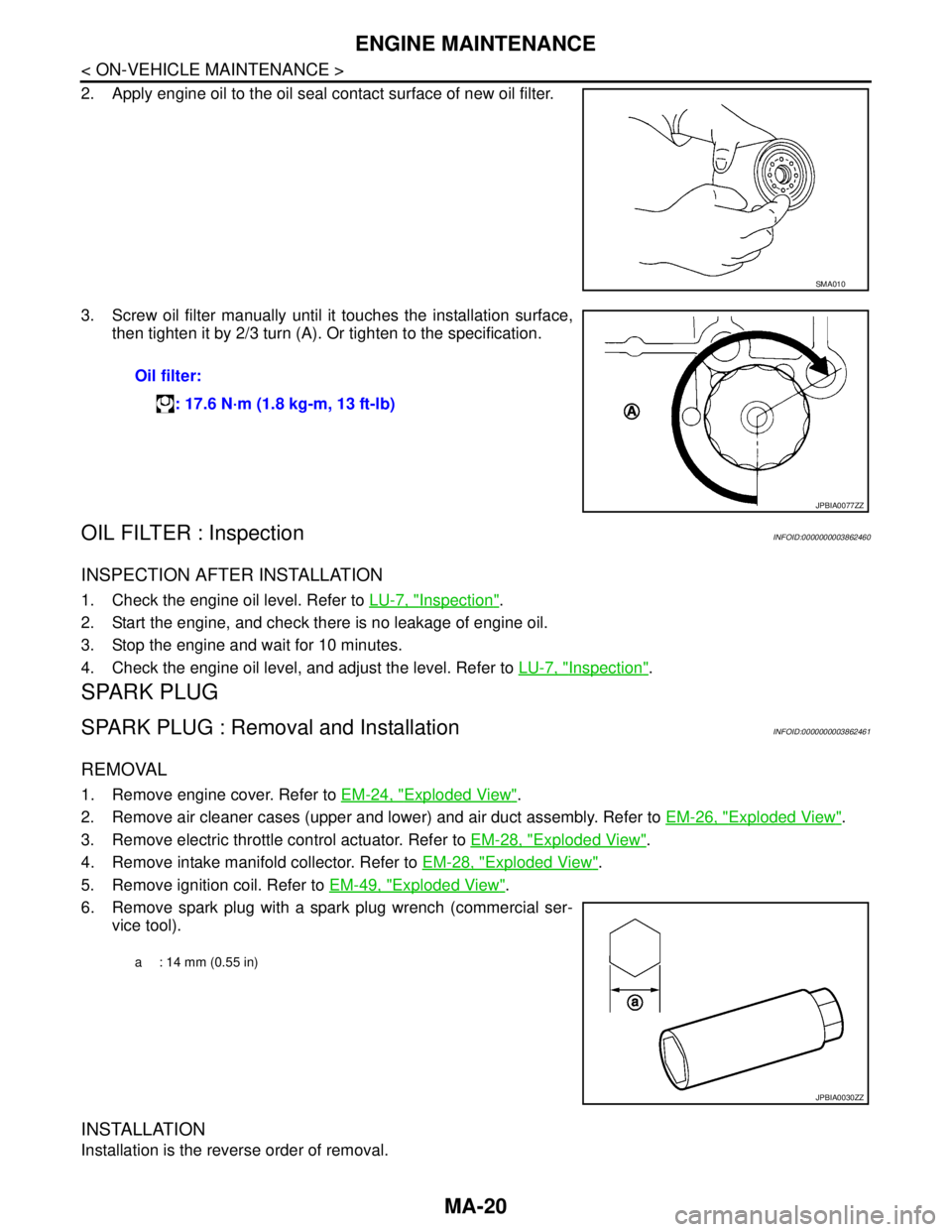
2. Apply engine oil to the oil seal contact surface of new oil filter.
3. Screw oil filter manually until it touches the installation surface,
then tighten it by 2/3 turn (A). Or tighten to the specification.
OIL FILTER : InspectionINFOID:0000000003862460
INSPECTION AFTER INSTALLATION
1. Check the engine oil level. Refer to LU-7, "Inspection".
2. Start the engine, and check there is no leakage of engine oil.
3. Stop the engine and wait for 10 minutes.
4. Check the engine oil level, and adjust the level. Refer to LU-7, "
Inspection".
SPARK PLUG
SPARK PLUG : Removal and InstallationINFOID:0000000003862461
REMOVAL
1. Remove engine cover. Refer to EM-24, "Exploded View".
2. Remove air cleaner cases (upper and lower) and air duct assembly. Refer to EM-26, "
Exploded View".
3. Remove electric throttle control actuator. Refer to EM-28, "
Exploded View".
4. Remove intake manifold collector. Refer to EM-28, "
Exploded View".
5. Remove ignition coil. Refer to EM-49, "
Exploded View".
6. Remove spark plug with a spark plug wrench (commercial ser-
vice tool).
INSTALLATION
Installation is the reverse order of removal.
SMA010
Oil filter:
: 17.6 N·m (1.8 kg-m, 13 ft-lb)
JPBIA0077ZZ
a : 14 mm (0.55 in)
JPBIA0030ZZ
Page 3211 of 5121
CHASSIS MAINTENANCE
MA-23
< ON-VEHICLE MAINTENANCE >
C
D
E
F
G
H
I
J
K
L
MB
MAN
OA
CHASSIS MAINTENANCE
HEADLAMP AIMING ADJUSTMENT (XENON TYPE)
HEADLAMP AIMING ADJUSTMENT (XENON TYPE) : DescriptionINFOID:0000000003862420
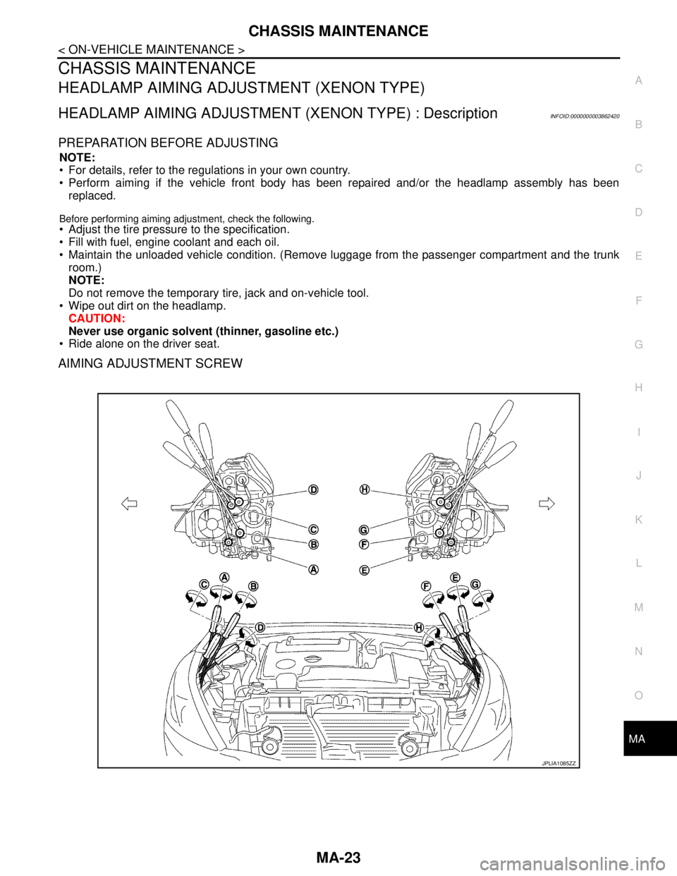
PREPARATION BEFORE ADJUSTING
NOTE:
For details, refer to the regulations in your own country.
Perform aiming if the vehicle front body has been repaired and/or the headlamp assembly has been
replaced.
Before performing aiming adjustment, check the following. Adjust the tire pressure to the specification.
Fill with fuel, engine coolant and each oil.
Maintain the unloaded vehicle condition. (Remove luggage from the passenger compartment and the trunk
room.)
NOTE:
Do not remove the temporary tire, jack and on-vehicle tool.
Wipe out dirt on the headlamp.
CAUTION:
Never use organic solvent (thinner, gasoline etc.)
Ride alone on the driver seat.
AIMING ADJUSTMENT SCREW
JPLIA1085ZZ
Page 3215 of 5121
CHASSIS MAINTENANCE
MA-27
< ON-VEHICLE MAINTENANCE >
C
D
E
F
G
H
I
J
K
L
MB
MAN
OA
Unit: mm (in)
HEADLAMP AIMING ADJUSTMENT (HALOGEN TYPE)
HEADLAMP AIMING ADJUSTMENT (HALOGEN TYPE) : DescriptionINFOID:0000000003862423
PREPARATION BEFORE ADJUSTING
NOTE:
For details, refer to the regulations in your own country.
Perform aiming if the vehicle front body has been repaired and/or the headlamp assembly has been
replaced.
Before performing aiming adjustment, check the following.
Adjust the tire pressure to the specification.
Fill with fuel, engine coolant and each oil.
Maintain the unloaded vehicle condition. (Remove luggage from the passenger compartment and the trunk
room.)
NOTE:
Do not remove the temporary tire, jack and on-vehicle tool.
Wipe out dirt on the headlamp.
CAUTION:
Never use organic solvent (thinner, gasoline etc.)
Ride alone on the driver seat.
Headlamp aiming switch sets to “0”.
AIMING ADJUSTMENT SCREW
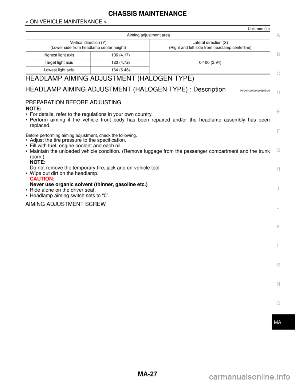
Aiming adjustment area
Vertical direction (Y)
(Lower side from headlamp center height)Lateral direction (X)
(Right and left side from headlamp centerline)
Highest light axis 106 (4.17)
0-100 (3.94) Target light axis 120 (4.72)
Lowest light axis 164 (6.46)
Page 3221 of 5121
CHASSIS MAINTENANCE
MA-33
< ON-VEHICLE MAINTENANCE >
C
D
E
F
G
H
I
J
K
L
MB
MAN
OA
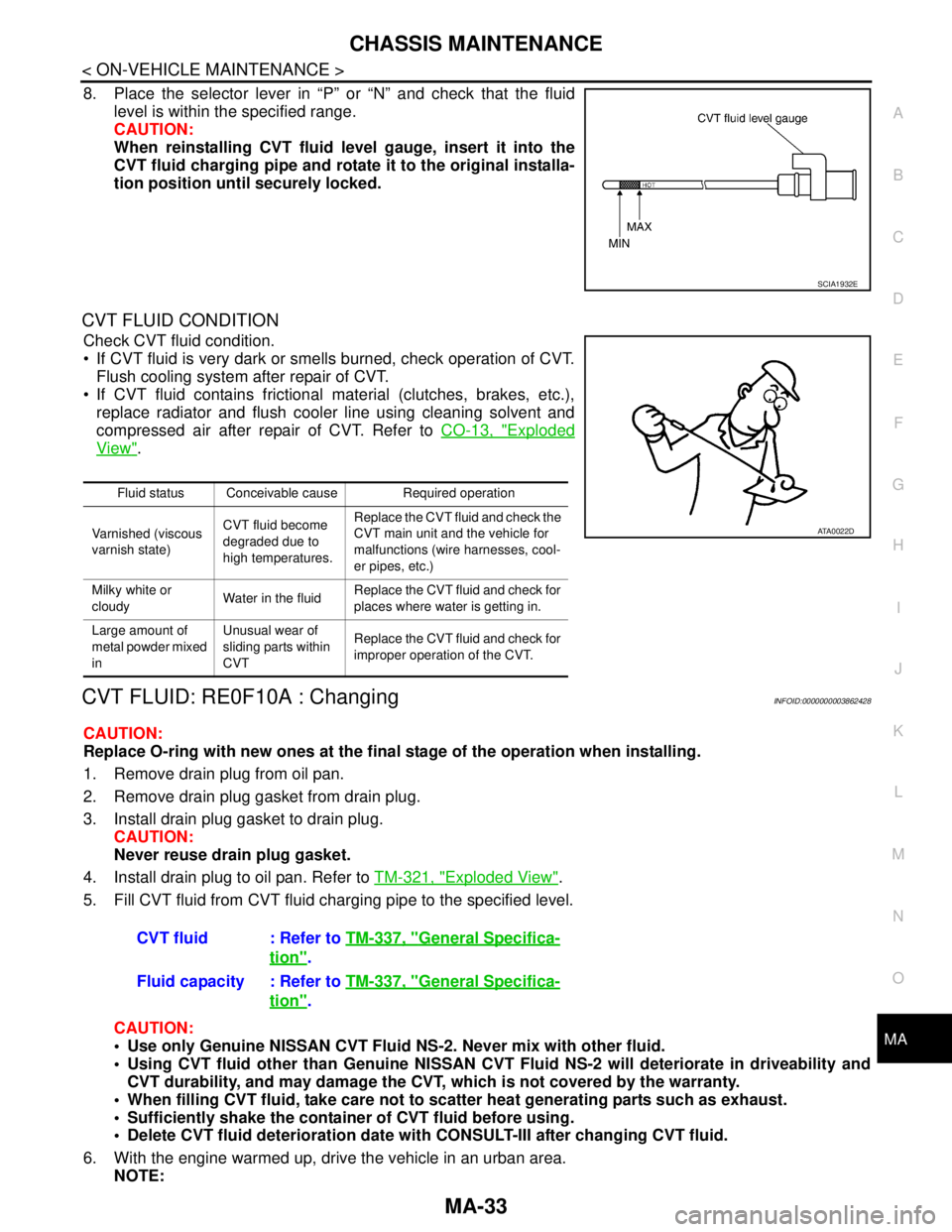
8. Place the selector lever in “P” or “N” and check that the fluid
level is within the specified range.
CAUTION:
When reinstalling CVT fluid level gauge, insert it into the
CVT fluid charging pipe and rotate it to the original installa-
tion position until securely locked.
CVT FLUID CONDITION
Check CVT fluid condition.
If CVT fluid is very dark or smells burned, check operation of CVT.
Flush cooling system after repair of CVT.
If CVT fluid contains frictional material (clutches, brakes, etc.),
replace radiator and flush cooler line using cleaning solvent and
compressed air after repair of CVT. Refer to CO-13, "
Exploded
View".
CVT FLUID: RE0F10A : ChangingINFOID:0000000003862428
CAUTION:
Replace O-ring with new ones at the final stage of the operation when installing.
1. Remove drain plug from oil pan.
2. Remove drain plug gasket from drain plug.
3. Install drain plug gasket to drain plug.
CAUTION:
Never reuse drain plug gasket.
4. Install drain plug to oil pan. Refer to TM-321, "
Exploded View".
5. Fill CVT fluid from CVT fluid charging pipe to the specified level.
CAUTION:
Use only Genuine NISSAN CVT Fluid NS-2. Never mix with other fluid.
Using CVT fluid other than Genuine NISSAN CVT Fluid NS-2 will deteriorate in driveability and
CVT durability, and may damage the CVT, which is not covered by the warranty.
When filling CVT fluid, take care not to scatter heat generating parts such as exhaust.
Sufficiently shake the container of CVT fluid before using.
Delete CVT fluid deterioration date with CONSULT-III after changing CVT fluid.
6. With the engine warmed up, drive the vehicle in an urban area.
NOTE:
SCIA1932E
Fluid status Conceivable cause Required operation
Varnished (viscous
varnish state)CVT fluid become
degraded due to
high temperatures.Replace the CVT fluid and check the
CVT main unit and the vehicle for
malfunctions (wire harnesses, cool-
er pipes, etc.)
Milky white or
cloudyWater in the fluidReplace the CVT fluid and check for
places where water is getting in.
Large amount of
metal powder mixed
inUnusual wear of
sliding parts within
CVTReplace the CVT fluid and check for
improper operation of the CVT.
ATA0022D
CVT fluid : Refer to TM-337, "General Specifica-
tion".
Fluid capacity : Refer to TM-337, "
General Specifica-
tion".
Page 3223 of 5121
CHASSIS MAINTENANCE
MA-35
< ON-VEHICLE MAINTENANCE >
C
D
E
F
G
H
I
J
K
L
MB
MAN
OA
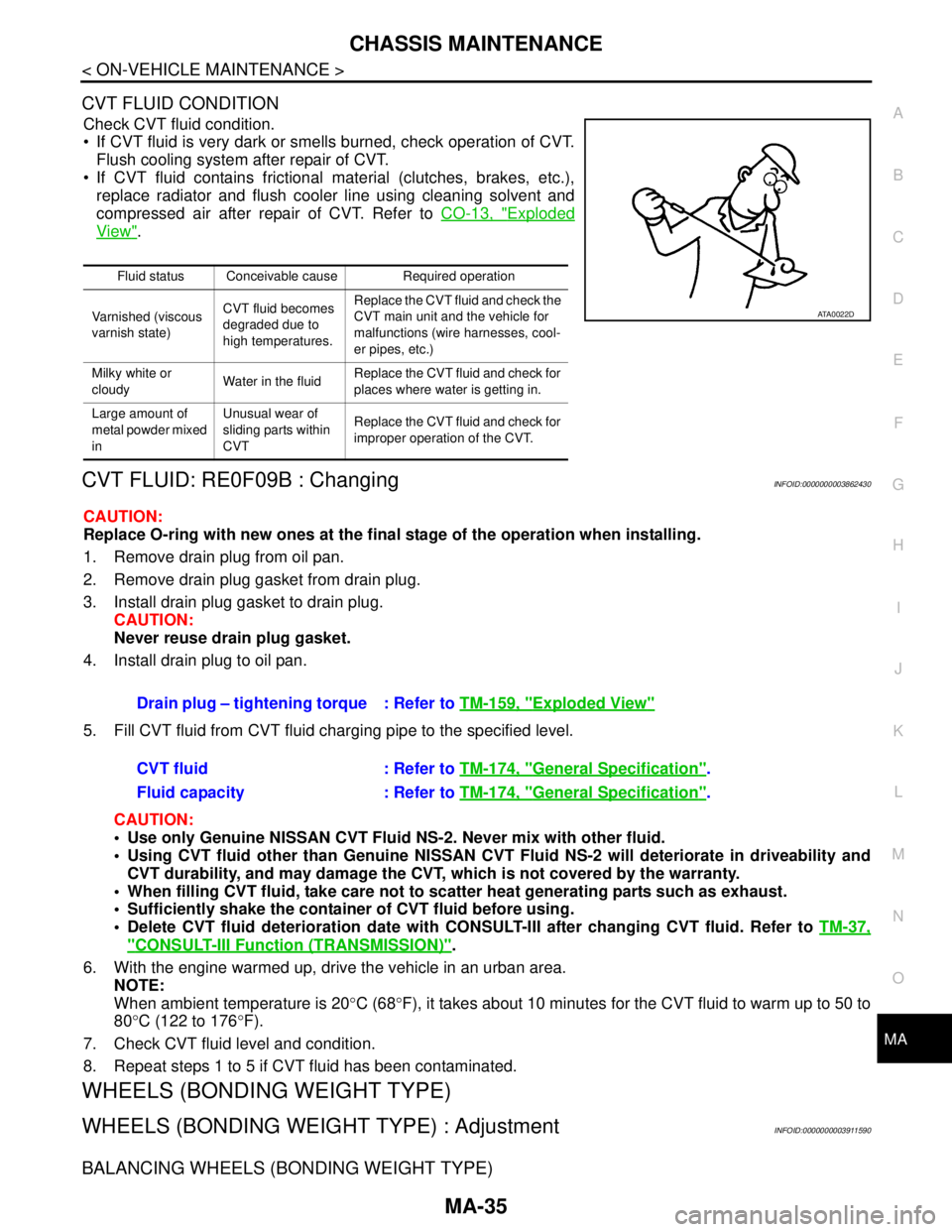
CVT FLUID CONDITION
Check CVT fluid condition.
If CVT fluid is very dark or smells burned, check operation of CVT.
Flush cooling system after repair of CVT.
If CVT fluid contains frictional material (clutches, brakes, etc.),
replace radiator and flush cooler line using cleaning solvent and
compressed air after repair of CVT. Refer to CO-13, "
Exploded
View".
CVT FLUID: RE0F09B : ChangingINFOID:0000000003862430
CAUTION:
Replace O-ring with new ones at the final stage of the operation when installing.
1. Remove drain plug from oil pan.
2. Remove drain plug gasket from drain plug.
3. Install drain plug gasket to drain plug.
CAUTION:
Never reuse drain plug gasket.
4. Install drain plug to oil pan.
5. Fill CVT fluid from CVT fluid charging pipe to the specified level.
CAUTION:
Use only Genuine NISSAN CVT Fluid NS-2. Never mix with other fluid.
Using CVT fluid other than Genuine NISSAN CVT Fluid NS-2 will deteriorate in driveability and
CVT durability, and may damage the CVT, which is not covered by the warranty.
When filling CVT fluid, take care not to scatter heat generating parts such as exhaust.
Sufficiently shake the container of CVT fluid before using.
Delete CVT fluid deterioration date with CONSULT-III after changing CVT fluid. Refer to TM-37,
"CONSULT-III Function (TRANSMISSION)".
6. With the engine warmed up, drive the vehicle in an urban area.
NOTE:
When ambient temperature is 20°C (68°F), it takes about 10 minutes for the CVT fluid to warm up to 50 to
80°C (122 to 176°F).
7. Check CVT fluid level and condition.
8. Repeat steps 1 to 5 if CVT fluid has been contaminated.
WHEELS (BONDING WEIGHT TYPE)
WHEELS (BONDING WEIGHT TYPE) : AdjustmentINFOID:0000000003911590
BALANCING WHEELS (BONDING WEIGHT TYPE)
Fluid status Conceivable cause Required operation
Varnished (viscous
varnish state)CVT fluid becomes
degraded due to
high temperatures.Replace the CVT fluid and check the
CVT main unit and the vehicle for
malfunctions (wire harnesses, cool-
er pipes, etc.)
Milky white or
cloudyWater in the fluidReplace the CVT fluid and check for
places where water is getting in.
Large amount of
metal powder mixed
inUnusual wear of
sliding parts within
CVTReplace the CVT fluid and check for
improper operation of the CVT.
ATA0022D
Drain plug – tightening torque : Refer to TM-159, "Exploded View"
CVT fluid : Refer to TM-174, "General Specification".
Fluid capacity : Refer to TM-174, "
General Specification".
Page 3228 of 5121
MA-40
< ON-VEHICLE MAINTENANCE >
CHASSIS MAINTENANCE
POWER STEERING FLUID AND LINES : Inspection
INFOID:0000000003862441
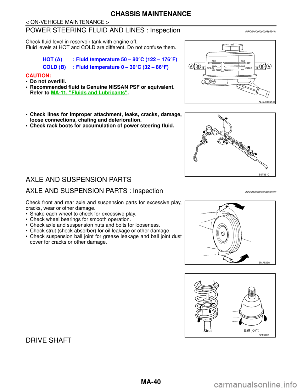
Check fluid level in reservoir tank with engine off.
Fluid levels at HOT and COLD are different. Do not confuse them.
CAUTION:
Do not overfill.
Recommended fluid is Genuine NISSAN PSF or equivalent.
Refer to MA-11, "
Fluids and Lubricants".
Check lines for improper attachment, leaks, cracks, damage,
loose connections, chafing and deterioration.
Check rack boots for accumulation of power steering fluid.
AXLE AND SUSPENSION PARTS
AXLE AND SUSPENSION PARTS : InspectionINFOID:0000000003858316
Check front and rear axle and suspension parts for excessive play,
cracks, wear or other damage.
Shake each wheel to check for excessive play.
Check wheel bearings for smooth operation.
Check axle and suspension nuts and bolts for looseness.
Check strut (shock absorber) for oil leakage or other damage.
Check suspension ball joint for grease leakage and ball joint dust
cover for cracks or other damage.
DRIVE SHAFT
HOT (A) : Fluid temperature 50 – 80°C (122 – 176°F)
COLD (B) : Fluid temperature 0 – 30°C (32 – 86°F)
ALGIA0002GB
SST851C
SMA525A
SFA392B