2008 NISSAN TEANA engine oil
[x] Cancel search: engine oilPage 3230 of 5121
MA-42
< ON-VEHICLE MAINTENANCE >
BODY MAINTENANCE
BODY MAINTENANCE
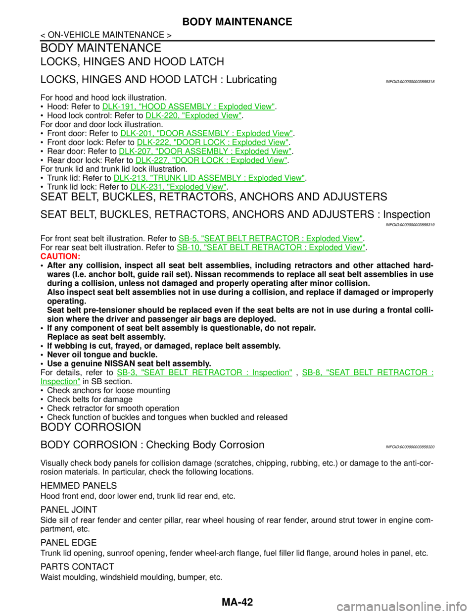
LOCKS, HINGES AND HOOD LATCH
LOCKS, HINGES AND HOOD LATCH : LubricatingINFOID:0000000003858318
For hood and hood lock illustration.
Hood: Refer to DLK-191, "
HOOD ASSEMBLY : Exploded View".
Hood lock control: Refer to DLK-220, "
Exploded View".
For door and door lock illustration.
Front door: Refer to DLK-201, "
DOOR ASSEMBLY : Exploded View".
Front door lock: Refer to DLK-222, "
DOOR LOCK : Exploded View".
Rear door: Refer to DLK-207, "
DOOR ASSEMBLY : Exploded View".
Rear door lock: Refer to DLK-227, "
DOOR LOCK : Exploded View".
For trunk lid and trunk lid lock illustration.
Trunk lid: Refer to DLK-213, "
TRUNK LID ASSEMBLY : Exploded View".
Trunk lid lock: Refer to DLK-231, "
Exploded View".
SEAT BELT, BUCKLES, RETRACTORS, ANCHORS AND ADJUSTERS
SEAT BELT, BUCKLES, RETRACTORS, ANCHORS AND ADJUSTERS : Inspection
INFOID:0000000003858319
For front seat belt illustration. Refer to SB-5, "SEAT BELT RETRACTOR : Exploded View".
For rear seat belt illustration. Refer to SB-10, "
SEAT BELT RETRACTOR : Exploded View".
CAUTION:
After any collision, inspect all seat belt assemblies, including retractors and other attached hard-
wares (I.e. anchor bolt, guide rail set). Nissan recommends to replace all seat belt assemblies in use
during a collision, unless not damaged and properly operating after minor collision.
Also inspect seat belt assemblies not in use during a collision, and replace if damaged or improperly
operating.
Seat belt pre-tensioner should be replaced even if the seat belts are not in use during a frontal colli-
sion where the driver and passenger air bags are deployed.
If any component of seat belt assembly is questionable, do not repair.
Replace as seat belt assembly.
If webbing is cut, frayed, or damaged, replace belt assembly.
Never oil tongue and buckle.
Use a genuine NISSAN seat belt assembly.
For details, refer to SB-3, "
SEAT BELT RETRACTOR : Inspection" , SB-8, "SEAT BELT RETRACTOR :
Inspection" in SB section.
Check anchors for loose mounting
Check belts for damage
Check retractor for smooth operation
Check function of buckles and tongues when buckled and released
BODY CORROSION
BODY CORROSION : Checking Body CorrosionINFOID:0000000003858320
Visually check body panels for collision damage (scratches, chipping, rubbing, etc.) or damage to the anti-cor-
rosion materials. In particular, check the following locations.
HEMMED PANELS
Hood front end, door lower end, trunk lid rear end, etc.
PA N E L J O I N T
Side sill of rear fender and center pillar, rear wheel housing of rear fender, around strut tower in engine com-
partment, etc.
PA N E L E D G E
Trunk lid opening, sunroof opening, fender wheel-arch flange, fuel filler lid flange, around holes in panel, etc.
PARTS CONTACT
Waist moulding, windshield moulding, bumper, etc.
Page 3232 of 5121
MA-44
< SERVICE DATA AND SPECIFICATIONS (SDS)
SERVICE DATA AND SPECIFICATIONS (SDS)
SERVICE DATA AND SPECIFICATIONS (SDS)
SERVICE DATA AND SPECIFICATIONS (SDS)
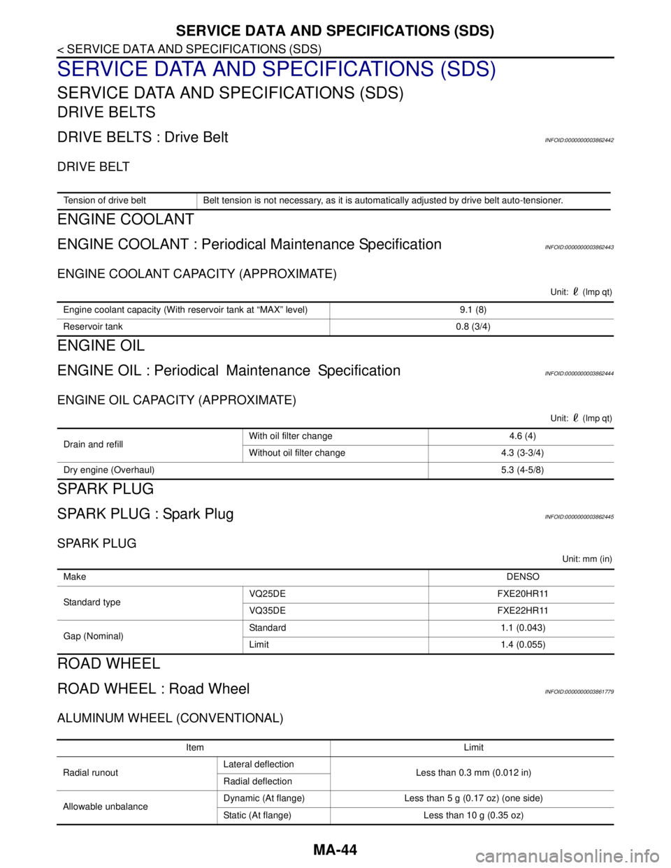
DRIVE BELTS
DRIVE BELTS : Drive BeltINFOID:0000000003862442
DRIVE BELT
ENGINE COOLANT
ENGINE COOLANT : Periodical Maintenance SpecificationINFOID:0000000003862443
ENGINE COOLANT CAPACITY (APPROXIMATE)
Unit: (lmp qt)
ENGINE OIL
ENGINE OIL : PeriodicalMaintenance SpecificationINFOID:0000000003862444
ENGINE OIL CAPACITY (APPROXIMATE)
Unit: (lmp qt)
SPARK PLUG
SPARK PLUG : Spark PlugINFOID:0000000003862445
SPARK PLUG
Unit: mm (in)
ROAD WHEEL
ROAD WHEEL : Road WheelINFOID:0000000003861779
ALUMINUM WHEEL (CONVENTIONAL)
Tension of drive belt Belt tension is not necessary, as it is automatically adjusted by drive belt auto-tensioner.
Engine coolant capacity (With reservoir tank at “MAX” level) 9.1 (8)
Reservoir tank0.8 (3/4)
Drain and refill With oil filter change 4.6 (4)
Without oil filter change 4.3 (3-3/4)
Dry engine (Overhaul)5.3 (4-5/8)
MakeDENSO
Standard typeVQ25DE FXE20HR11
VQ35DE FXE22HR11
Gap (Nominal)Standard 1.1 (0.043)
Limit 1.4 (0.055)
Item Limit
Radial runoutLateral deflection
Less than 0.3 mm (0.012 in)
Radial deflection
Allowable unbalanceDynamic (At flange) Less than 5 g (0.17 oz) (one side)
Static (At flange) Less than 10 g (0.35 oz)
Page 3256 of 5121

MWI-2
DIAGNOSIS SYSTEM (METER) .......................32
Diagnosis Description .............................................32
CONSULT-III Function (METER/M&A) ...................33
COMPONENT DIAGNOSIS ........................37
U1000 CAN COMM CIRCUIT ............................37
Description ..............................................................37
DTC Logic ...............................................................37
Diagnosis Procedure .............................................37
U1010 CONTROL UNIT (CAN) .........................38
Description ..............................................................38
DTC Logic ...............................................................38
Diagnosis Procedure ..............................................38
B2205 VEHICLE SPEED ...................................39
Description ..............................................................39
DTC Logic ...............................................................39
Diagnosis Procedure .............................................39
B2267 ENGINE SPEED .....................................40
Description ..............................................................40
DTC Logic ...............................................................40
Diagnosis Procedure ..............................................40
B2268 WATER TEMP ........................................41
Description ..............................................................41
DTC Logic ...............................................................41
Diagnosis Procedure ..............................................41
POWER SUPPLY AND GROUND CIRCUIT .....42
COMBINATION METER ...........................................42
COMBINATION METER : Diagnosis Procedure ....42
BCM (BODY CONTROL MODULE) .........................42
BCM (BODY CONTROL MODULE) : Diagnosis
Procedure ...............................................................
42
IPDM E/R (INTELLIGENT POWER DISTRIBU-
TION MODULE ENGINE ROOM) .............................
43
IPDM E/R (INTELLIGENT POWER DISTRIBU-
TION MODULE ENGINE ROOM) : Diagnosis Pro-
cedure .....................................................................
43
FUEL LEVEL SENSOR SIGNAL CIRCUIT .......45
Description ..............................................................45
Component Function Check ...................................45
Diagnosis Procedure .............................................45
Component Inspection ............................................46
METER CONTROL SWITCH SIGNAL CIR-
CUIT ...................................................................
48
Description ..............................................................48
Diagnosis Procedure ..............................................48
Component Inspection ............................................49
OIL PRESSURE SWITCH SIGNAL CIRCUIT ...50
Description ..............................................................50
Component Function Check ...................................50
Diagnosis Procedure ..............................................50
Component Inspection ............................................50
PARKING BRAKE SWITCH SIGNAL CIR-
CUIT ...................................................................
52
Description ..............................................................52
Diagnosis Procedure ...............................................52
Component Inspection ............................................52
ECU DIAGNOSIS .......................................53
COMBINATION METER ....................................53
Reference Value .....................................................53
Wiring Diagram - METER - .....................................59
Fail-Safe ..................................................................66
DTC Index ...............................................................67
BCM (BODY CONTROL MODULE) ..................68
Reference Value .....................................................68
Wiring Diagram - BCM - ..........................................91
Fail-safe ..................................................................97
DTC Inspection Priority Chart ...............................99
DTC Index ............................................................100
IPDM E/R (INTELLIGENT POWER DISTRI-
BUTION MODULE ENGINE ROOM) ................
102
Reference Value ...................................................102
Wiring Diagram - IPDM E/R - ................................110
Fail-safe ................................................................113
DTC Index ............................................................115
SYMPTOM DIAGNOSIS ...........................116
THE FUEL GAUGE POINTER DOES NOT
MOVE ................................................................
116
Description ............................................................116
Diagnosis Procedure .............................................116
THE METER CONTROL SWITCH IS INOPER-
ATIVE ................................................................
117
Description ............................................................117
Diagnosis Procedure .............................................117
THE OIL PRESSURE WARNING LAMP
DOES NOT TURN ON ......................................
118
Description ............................................................118
Diagnosis Procedure .............................................118
THE OIL PRESSURE WARNING LAMP
DOES NOT TURN OFF ....................................
119
Description ............................................................119
Diagnosis Procedure .............................................119
THE PARKING BRAKE RELEASE WARNING
CONTINUES DISPLAYING, OR DOES NOT
DISPLAY ...........................................................
120
Description ............................................................120
Diagnosis Procedure .............................................120
THE DOOR OPEN WARNING CONTINUES
DISPLAYING, OR DOES NOT DISPLAY ........
121
Description ............................................................121
Page 3261 of 5121
MWI
METER SYSTEM
MWI-7
< FUNCTION DIAGNOSIS >
C
D
E
F
G
H
I
J
K
L
MB A
O
P
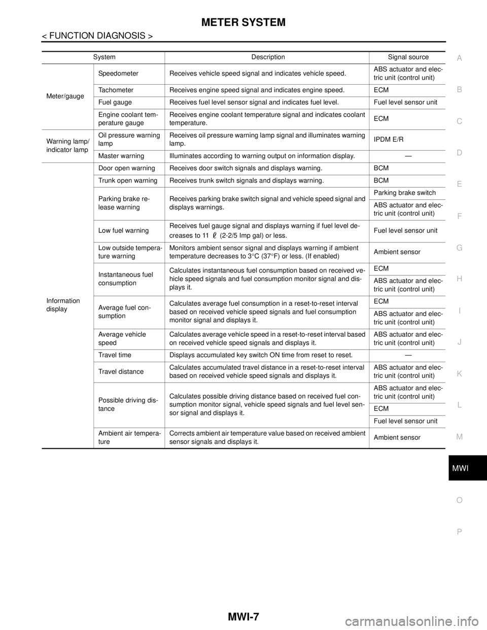
System Description Signal source
Meter/gaugeSpeedometer Receives vehicle speed signal and indicates vehicle speed.ABS actuator and elec-
tric unit (control unit)
Tachometer Receives engine speed signal and indicates engine speed. ECM
Fuel gauge Receives fuel level sensor signal and indicates fuel level. Fuel level sensor unit
Engine coolant tem-
perature gaugeReceives engine coolant temperature signal and indicates coolant
temperature.ECM
Warning lamp/
indicator lampOil pressure warning
lampReceives oil pressure warning lamp signal and illuminates warning
lamp.IPDM E/R
Master warning Illuminates according to warning output on information display. —
Information
displayDoor open warning Receives door switch signals and displays warning. BCM
Trunk open warning Receives trunk switch signals and displays warning. BCM
Parking brake re-
lease warningReceives parking brake switch signal and vehicle speed signal and
displays warnings.Parking brake switch
ABS actuator and elec-
tric unit (control unit)
Low fuel warningReceives fuel gauge signal and displays warning if fuel level de-
creases to 11 (2-2/5 Imp gal) or less.Fuel level sensor unit
Low outside tempera-
ture warningMonitors ambient sensor signal and displays warning if ambient
temperature decreases to 3°C (37°F) or less. (If enabled)Ambient sensor
Instantaneous fuel
consumptionCalculates instantaneous fuel consumption based on received ve-
hicle speed signals and fuel consumption monitor signal and dis-
plays it.ECM
ABS actuator and elec-
tric unit (control unit)
Average fuel con-
sumptionCalculates average fuel consumption in a reset-to-reset interval
based on received vehicle speed signals and fuel consumption
monitor signal and displays it.ECM
ABS actuator and elec-
tric unit (control unit)
Average vehicle
speedCalculates average vehicle speed in a reset-to-reset interval based
on received vehicle speed signals and displays it.ABS actuator and elec-
tric unit (control unit)
Travel time Displays accumulated key switch ON time from reset to reset. —
Travel distanceCalculates accumulated travel distance in a reset-to-reset interval
based on received vehicle speed signals and displays it.ABS actuator and elec-
tric unit (control unit)
Possible driving dis-
tanceCalculates possible driving distance based on received fuel con-
sumption monitor signal, vehicle speed signals and fuel level sen-
sor signal and displays it.ABS actuator and elec-
tric unit (control unit)
ECM
Fuel level sensor unit
Ambient air tempera-
tureCorrects ambient air temperature value based on received ambient
sensor signals and displays it.Ambient sensor
Page 3263 of 5121
MWI
METER SYSTEM
MWI-9
< FUNCTION DIAGNOSIS >
C
D
E
F
G
H
I
J
K
L
MB A
O
P
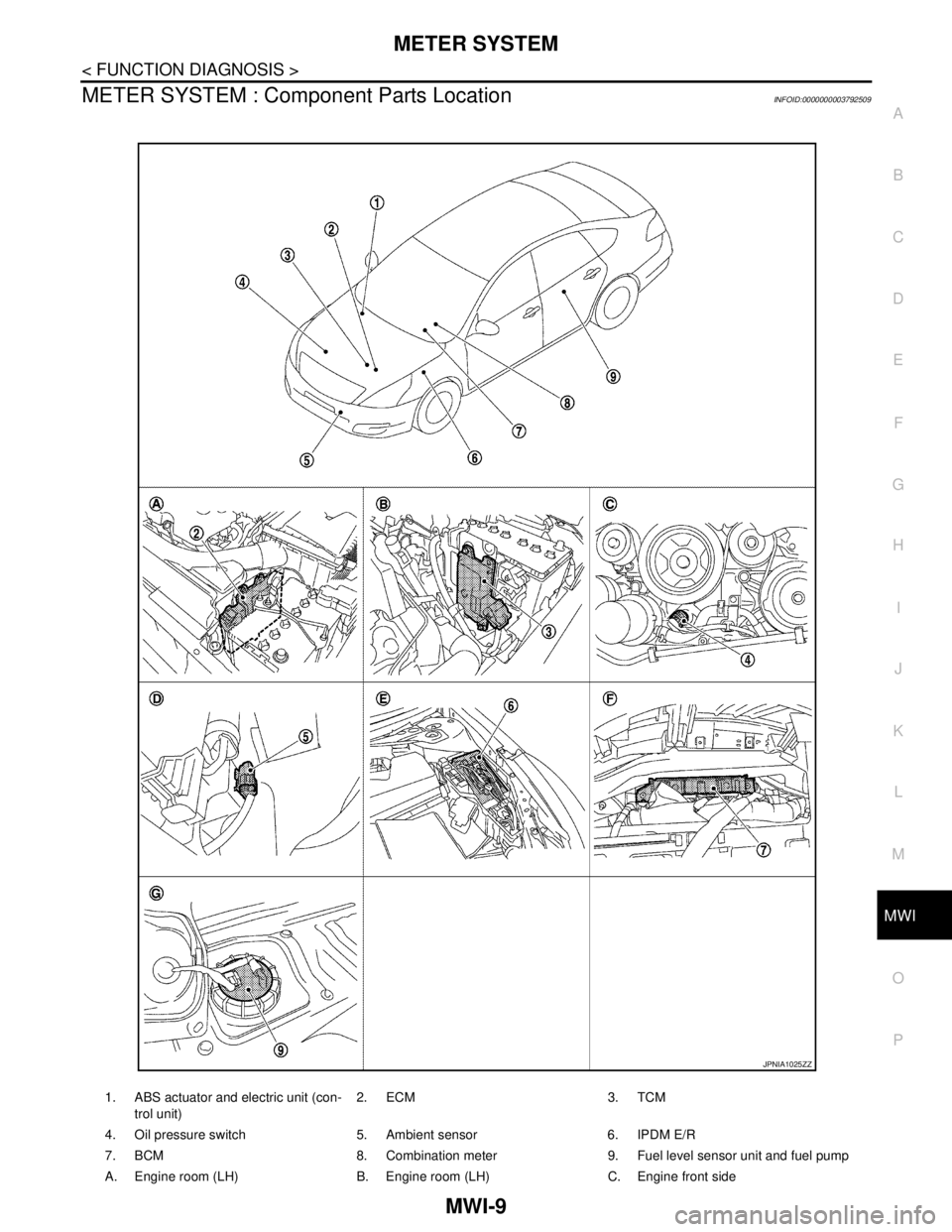
METER SYSTEM : Component Parts LocationINFOID:0000000003792509
1. ABS actuator and electric unit (con-
trol unit)2. ECM 3. TCM
4. Oil pressure switch 5. Ambient sensor 6. IPDM E/R
7. BCM 8. Combination meter 9. Fuel level sensor unit and fuel pump
A. Engine room (LH) B. Engine room (LH) C. Engine front side
JPNIA1025ZZ
Page 3264 of 5121
MWI-10
< FUNCTION DIAGNOSIS >
METER SYSTEM
METER SYSTEM : Component Description
INFOID:0000000003792510
SPEEDOMETER
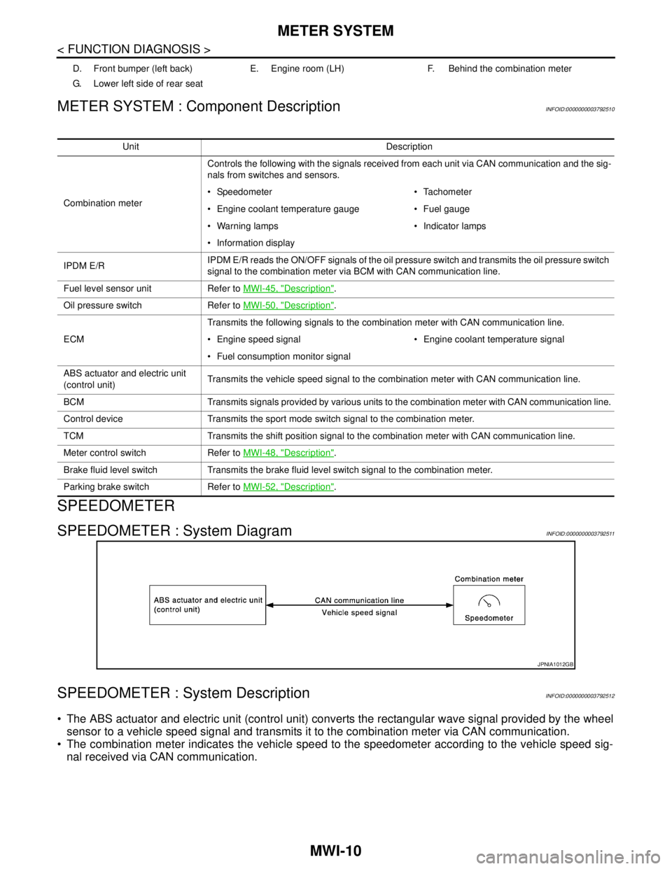
SPEEDOMETER : System DiagramINFOID:0000000003792511
SPEEDOMETER : System DescriptionINFOID:0000000003792512
The ABS actuator and electric unit (control unit) converts the rectangular wave signal provided by the wheel
sensor to a vehicle speed signal and transmits it to the combination meter via CAN communication.
The combination meter indicates the vehicle speed to the speedometer according to the vehicle speed sig-
nal received via CAN communication.
D. Front bumper (left back) E. Engine room (LH) F. Behind the combination meter
G. Lower left side of rear seat
Unit Description
Combination meterControls the following with the signals received from each unit via CAN communication and the sig-
nals from switches and sensors.
Speedometer Tachometer
Engine coolant temperature gauge Fuel gauge
Warning lamps Indicator lamps
Information display
IPDM E/RIPDM E/R reads the ON/OFF signals of the oil pressure switch and transmits the oil pressure switch
signal to the combination meter via BCM with CAN communication line.
Fuel level sensor unit Refer to MWI-45, "
Description".
Oil pressure switch Refer to MWI-50, "
Description".
ECMTransmits the following signals to the combination meter with CAN communication line.
Engine speed signal Engine coolant temperature signal
Fuel consumption monitor signal
ABS actuator and electric unit
(control unit)Transmits the vehicle speed signal to the combination meter with CAN communication line.
BCM Transmits signals provided by various units to the combination meter with CAN communication line.
Control device Transmits the sport mode switch signal to the combination meter.
TCM Transmits the shift position signal to the combination meter with CAN communication line.
Meter control switch Refer to MWI-48, "
Description".
Brake fluid level switch Transmits the brake fluid level switch signal to the combination meter.
Parking brake switch Refer to MWI-52, "
Description".
JPNIA1012GB
Page 3265 of 5121
MWI
METER SYSTEM
MWI-11
< FUNCTION DIAGNOSIS >
C
D
E
F
G
H
I
J
K
L
MB A
O
P
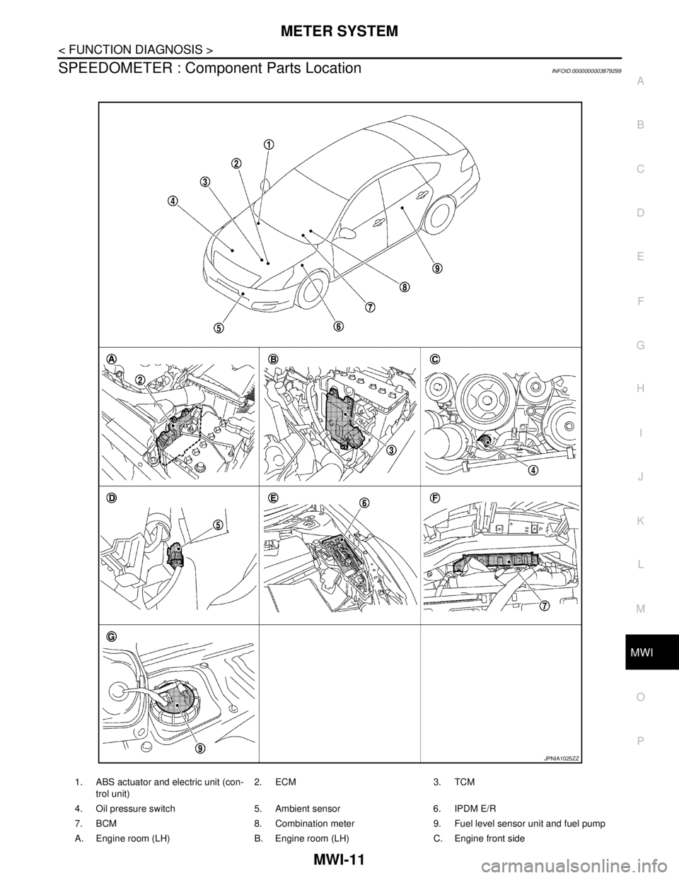
SPEEDOMETER : Component Parts LocationINFOID:0000000003879299
1. ABS actuator and electric unit (con-
trol unit)2. ECM 3. TCM
4. Oil pressure switch 5. Ambient sensor 6. IPDM E/R
7. BCM 8. Combination meter 9. Fuel level sensor unit and fuel pump
A. Engine room (LH) B. Engine room (LH) C. Engine front side
JPNIA1025ZZ
Page 3267 of 5121
MWI
METER SYSTEM
MWI-13
< FUNCTION DIAGNOSIS >
C
D
E
F
G
H
I
J
K
L
MB A
O
P
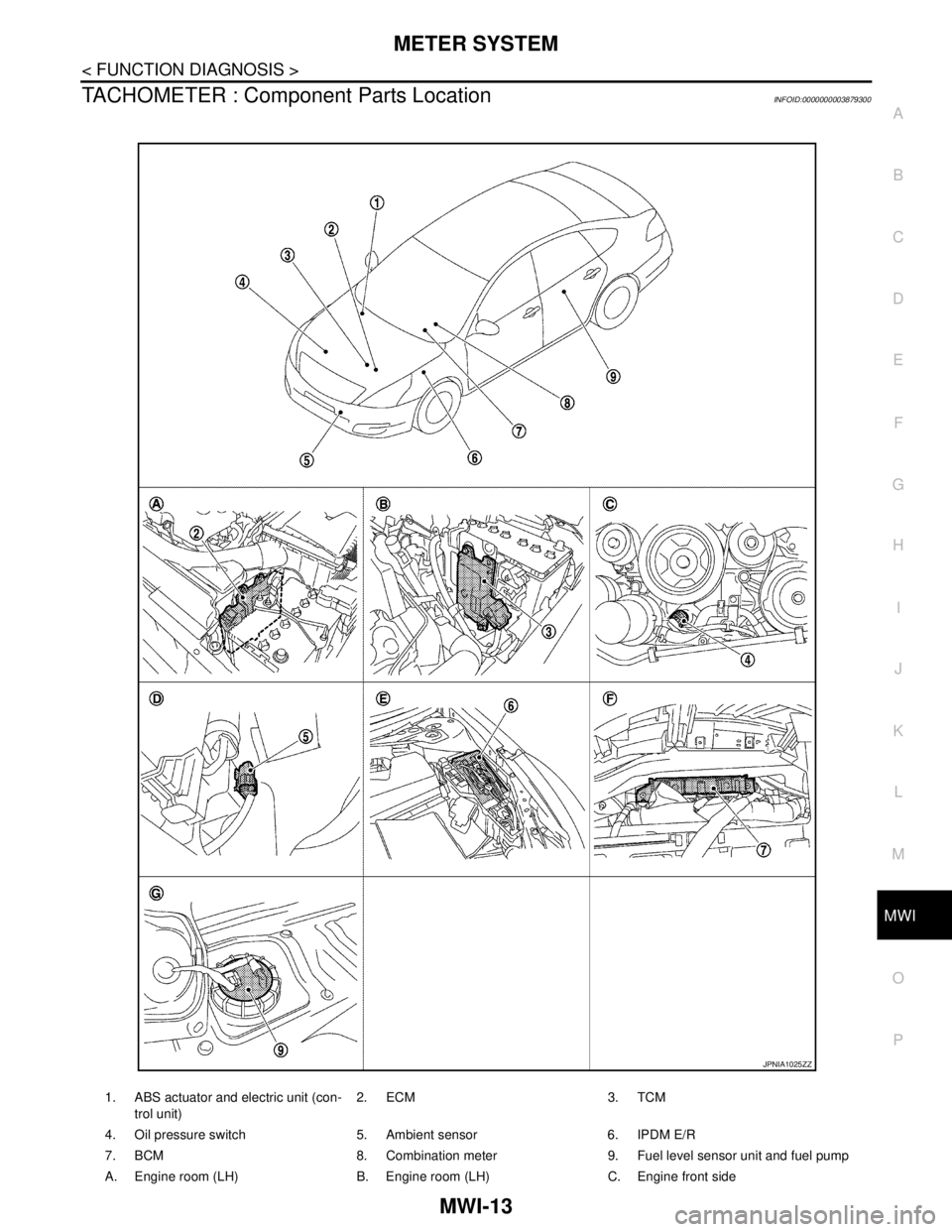
TACHOMETER : Component Parts LocationINFOID:0000000003879300
1. ABS actuator and electric unit (con-
trol unit)2. ECM 3. TCM
4. Oil pressure switch 5. Ambient sensor 6. IPDM E/R
7. BCM 8. Combination meter 9. Fuel level sensor unit and fuel pump
A. Engine room (LH) B. Engine room (LH) C. Engine front side
JPNIA1025ZZ