2008 NISSAN TEANA engine oil
[x] Cancel search: engine oilPage 2597 of 5121

HA-28
< ON-VEHICLE MAINTENANCE >
LUBRICANT
LUBRICANT
Maintenance of Lubricant QuantityINFOID:0000000003795916
The lubricant in the compressor circulates through the system the refrigerant. Add lubricant to compressor
when replacing any component or after a large refrigerant leakage occurred. It is important to maintain the
specified amount.
If lubricant quantity is not maintained properly, the following malfunctions may result:
Lack of lubricant: May lead to a seized compressor.
Excessive lubricant: Inadequate cooling (thermal exchange interference)
LUBRICANT
LUBRICANT RETURN OPERATION
Adjust the lubricant quantity according to the test group shown below.
1.CHECK LUBRICANT RETURN OPERATION
Can lubricant return operation be performed?
A/C system works normally.
There is no evidence of a large amount of lubricant leakage.
CAUTION:
Never perform the lubricant return operation if excessive lubricant leakage is detected.
Is it successful?
YES >> GO TO 2.
NO >> GO TO 3.
2.PERFORM LUBRICANT RETURN OPERATION
1. Start the engine, and set to the following conditions:
- Engine speed: Idling to 1,200 rpm
- A/C switch: ON
- Blower speed: Max. position
- Set temperature: FULL HOT
- Intake position: Recirculation (REC)
2. Perform lubricant return operation for approximately 10 minutes.
3. Stop the engine.
>> GO TO 3.
3.CHECK REPLACEMENT PART
Should the compressor be replaced?
YES >> Refer to HA-29, "Lubricant Adjusting Procedure for Compressor Replacement".
NO >> Refer to HA-28, "
Lubricant Adjusting Procedure for Components Replacement Except Compres-
sor".
Lubricant Adjusting Procedure for Components Replacement Except Compressor
INFOID:0000000003795917
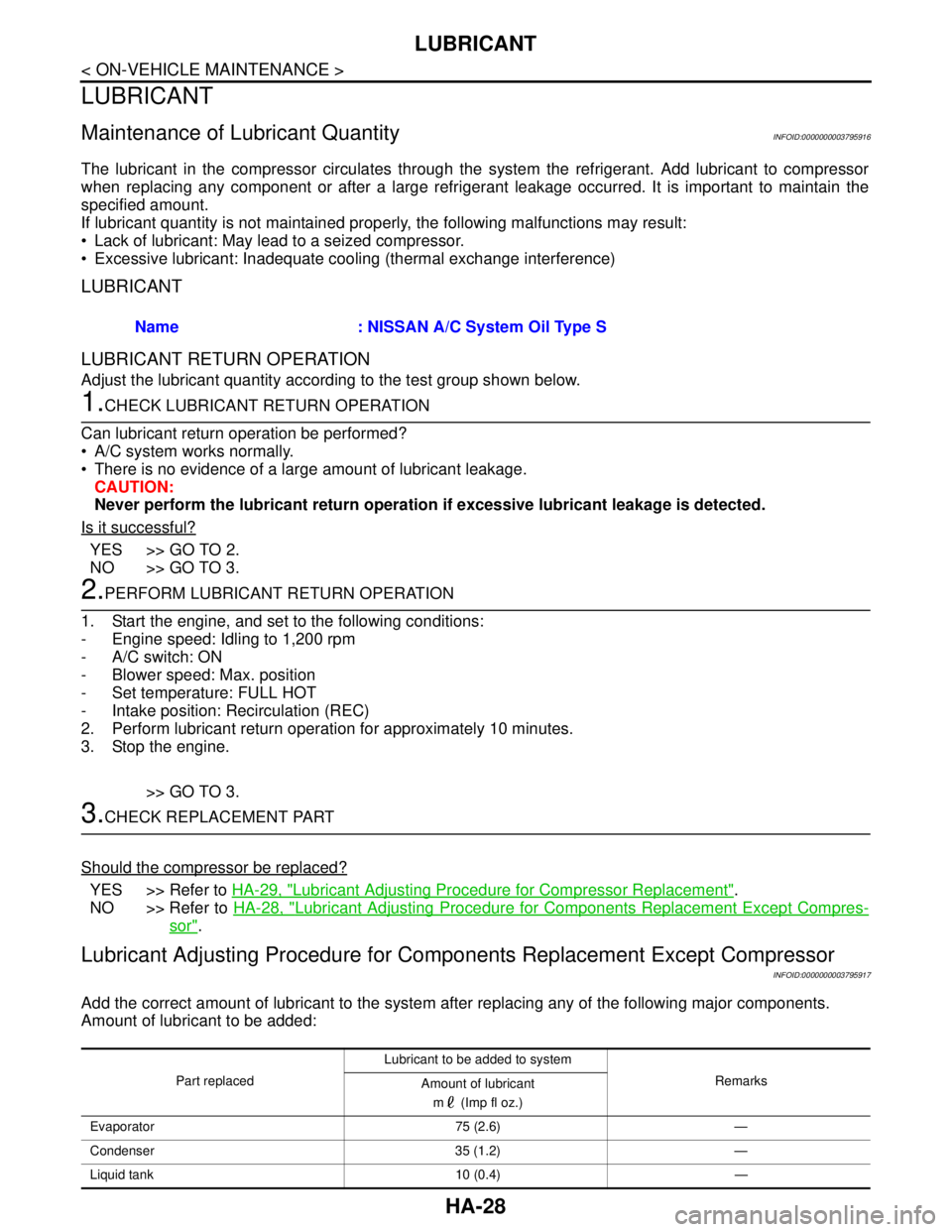
Add the correct amount of lubricant to the system after replacing any of the following major components.
Amount of lubricant to be added:Name : NISSAN A/C System Oil Type S
Part replacedLubricant to be added to system
Remarks
Amount of lubricant
m (Imp fl oz.)
Evaporator 75 (2.6) —
Condenser 35 (1.2) —
Liquid tank 10 (0.4) —
Page 2601 of 5121

HA-32
< ON-VEHICLE MAINTENANCE >
FLUORESCENT LEAK DETECTOR
FLUORESCENT LEAK DETECTOR
InspectionINFOID:0000000003795981
CHECKING SYSTEM FOR LEAKAGES USING THE FLUORESCENT LEAK DETECTOR
1. Check A/C system for leakages using the UV lamp and safety goggles (SST: J-42220) in a low sunlight
area (area without windows preferable). Illuminate all components, fittings and lines. The dye appears as
a bright green/yellow area at the point of leakage. Fluorescent dye observed at the evaporator drain open-
ing indicates an evaporator core assembly (tubes, core or expansion valve) leakage.
2. Use an adjustable mirror or wipe the area with a clean shop rag or cloth, with the UV lamp for dye residue
if the suspected area is difficult to see.
3. Remove any residual dye using dye cleaner (SST: J-43872) to prevent future misdiagnosis after the leak-
age is repaired.
4. Perform a system performance check and verify the leakage repair with an approved electrical leak detec-
tor.
NOTE:
Other gases in the work area or substances on the A/C components, for example, anti-freeze, windshield
washer fluid, solvents and lubricants, may falsely trigger the leak detector. Make sure the surfaces to be
checked are clean.
Clean with a dry cloth or blow off with shop air.
Do not allow the sensor tip of the detector to contact with any substance. This may also cause false readings
and may damage the detector.
DYE INJECTION
(This procedure is only necessary when recharging the system or when the compressor has seized and was
replaced.)
1. Check A/C system static (at rest) pressure. Pressure must be at least 345 kPa (3.45 bar, 3.52 kg/cm
2, 50
psi).
2. Pour one bottle (1/4 ounce / 7.4 cc) of the A/C refrigerant dye into the injector tool (SST: J-41459).
3. Connect the injector tool to the A/C low-pressure side service valve.
4. Start the engine. Then switch A/C ON.
5. Inject one bottle (1/4 ounce / 7.4 cc) of fluorescent dye through the low-pressure service valve using dye
injector tool (SST: J-41459) (refer to the manufacture’s operating instructions) when the A/C operating
(compressor running).
6. Disconnect the injector tool from the service valve with the engine still running.
CAUTION:
Be careful when replacing the A/C system or a component, pour the dye directly into the open sys-
tem connection and proceed with the service procedures.
7. Operate the A/C system for a minimum of 20 minutes to mix the dye with the system oil. Depending on the
leakage size, operating conditions and location of the leakage, it may take from minutes to days for the
dye to penetrate a leakage and become visible.
8. Attach a blue label if necessary.
Page 2628 of 5121

SERVICE DATA AND SPECIFICATIONS (SDS)
HA-59
< SERVICE DATA AND SPECIFICATIONS (SDS)
C
D
E
F
G
H
J
K
L
MA
B
HA
N
O
P
SERVICE DATA AND SPECIFICATIONS (SDS)
SERVICE DATA AND SPECIFICATIONS (SDS)
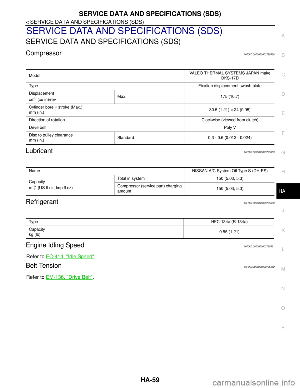
CompressorINFOID:0000000003795858
LubricantINFOID:0000000003795859
RefrigerantINFOID:0000000003795860
Engine Idling SpeedINFOID:0000000003795861
Refer to EC-414, "Idle Speed".
Belt TensionINFOID:0000000003795862
Refer to EM-136, "Drive Belt".
ModelVALEO THERMAL SYSTEMS JAPAN make
DKS-17D
Ty p eFixation displacement swash plate
Displacement
cm
3 (cu in)/revMax. 175 (10.7)
Cylinder bore × stroke (Max.)
mm (in.)30.5 (1.21) × 24 (0.95)
Direction of rotationClockwise (viewed from clutch)
Drive beltPoly V
Disc to pulley clearance
mm (in.)Standard 0.3 - 0.6 (0.012 - 0.024)
NameNISSAN A/C System Oil Type S (DH-PS)
Capacity
m (US fl oz, lmp fl oz)Total in system 150 (5.03, 5.3)
Compressor (service part) charging
amount150 (5.03, 5.3)
Ty p eHFC-134a (R-134a)
Capacity
kg (lb)0.55 (1.21)
Page 2696 of 5121
![NISSAN TEANA 2008 Service Manual HAC-68
< COMPONENT DIAGNOSIS >[WITHOUT 7 INCH DISPLAY]
BLOWER MOTOR
BLOWER MOTOR
DescriptionINFOID:0000000003846359
COMPONENT DESCRIPTION
Brush-less Motor
The blower motor utilizes a brush-less motor NISSAN TEANA 2008 Service Manual HAC-68
< COMPONENT DIAGNOSIS >[WITHOUT 7 INCH DISPLAY]
BLOWER MOTOR
BLOWER MOTOR
DescriptionINFOID:0000000003846359
COMPONENT DESCRIPTION
Brush-less Motor
The blower motor utilizes a brush-less motor](/manual-img/5/57391/w960_57391-2695.png)
HAC-68
< COMPONENT DIAGNOSIS >[WITHOUT 7 INCH DISPLAY]
BLOWER MOTOR
BLOWER MOTOR
DescriptionINFOID:0000000003846359
COMPONENT DESCRIPTION
Brush-less Motor
The blower motor utilizes a brush-less motor with a rotating magnet.
Quietness is improved over previous motors where the brush was
the point of contact and the coil rotated.
Blower Motor Circuit
Component Function CheckINFOID:0000000003846360
1.CHECK OPERATION
1. Warm up the engine.
2. Operate the fan control dial. Check that the fan speed and indicator are switched for all fan speeds.
Does it operate normally?
YES >> INSPECTION END
NO >> Perform trouble diagnosis for the blower motor. Refer to HAC-68, "
Diagnosis Procedure".
Diagnosis ProcedureINFOID:0000000003846361
1.CHECK WITH SELF-DIAGNOSIS FUNCTION OF CONSULT-III
1. Using CONSULT-III, perform “SELF-DIAGNOSIS RESULTS” of HVAC.
2. Check if any DTC is displayed in the self-diagnosis results.
NOTE:
If DTC is displayed along with DTC U1000 or U1010, first diagnose the DTC U1000 or U1010. Refer to HAC-
42, "DTC Logic" or HAC-43, "DTC Logic".
Is any DTC displayed?
YES >> Perform the diagnosis that is applicable to the sensor and actuator. Refer to HAC-85, "DTC
Index".
NO >> GO TO 2.
2.CHECK WITH ACTIVE TEST OF CONSULT-III
1. Using CONSULT-III, perform “HVAC TEST” “ACTIVE TEST” of HVAC to check each output device. Refer
to HAC-38, "
CONSULT-III Function".
NOTE:
Perform the ACTIVE TEST after starting the engine because the compressor is operated.
ZHA152H
JSIIA0999ZZ
Page 2821 of 5121
![NISSAN TEANA 2008 Service Manual BLOWER MOTOR
HAC-193
< COMPONENT DIAGNOSIS >[WITH 7 INCH DISPLAY]
C
D
E
F
G
H
J
K
L
MA
B
HAC
N
O
P
BLOWER MOTOR
DescriptionINFOID:0000000003884772
COMPONENT DESCRIPTION
Brush-less Motor
The blower mot NISSAN TEANA 2008 Service Manual BLOWER MOTOR
HAC-193
< COMPONENT DIAGNOSIS >[WITH 7 INCH DISPLAY]
C
D
E
F
G
H
J
K
L
MA
B
HAC
N
O
P
BLOWER MOTOR
DescriptionINFOID:0000000003884772
COMPONENT DESCRIPTION
Brush-less Motor
The blower mot](/manual-img/5/57391/w960_57391-2820.png)
BLOWER MOTOR
HAC-193
< COMPONENT DIAGNOSIS >[WITH 7 INCH DISPLAY]
C
D
E
F
G
H
J
K
L
MA
B
HAC
N
O
P
BLOWER MOTOR
DescriptionINFOID:0000000003884772
COMPONENT DESCRIPTION
Brush-less Motor
The blower motor utilizes a brush-less motor with a rotating magnet.
Quietness is improved over previous motors where the brush was
the point of contact and the coil rotated.
Blower Motor Circuit
Component Function CheckINFOID:0000000003884773
1.CHECK OPERATION
1. Warm up the engine.
2. Operate the fan control dial. Check that the fan speed and indicator are switched for all fan speeds.
Does it operate normally?
YES >> INSPECTION END
NO >> Perform trouble diagnosis for the blower motor. Refer to HAC-193, "
Diagnosis Procedure".
Diagnosis ProcedureINFOID:0000000003884774
1.CHECK WITH SELF-DIAGNOSIS FUNCTION OF CONSULT-III
1. Using CONSULT-III, perform “SELF-DIAGNOSIS RESULTS” of HVAC.
2. Check if any DTC is displayed in the self-diagnosis results.
NOTE:
If DTC is displayed along with DTC U1000 or U1010, first diagnose the DTC U1000 or U1010. Refer to HAC-
164, "DTC Logic" or HAC-165, "DTC Logic".
Is any DTC displayed?
YES >> Perform the diagnosis that is applicable to the sensor and actuator. Refer to HAC-212, "WITH-
OUT INTELLIGENT AIR CONDITIONER SYSTEM : DTC Index"WITHOUT INTELLIGENT AIR
CONDITIONER SYSTEM) or HAC-224, "
WITH INTELLIGENT AIR CONDITIONER SYSTEM :
DTC Index" (WITH INTELLIGENT AIR CONDITIONER SYSTEM).
NO >> GO TO 2.
2.CHECK WITH ACTIVE TEST OF CONSULT-III
1. Using CONSULT-III, perform “HVAC TEST” “ACTIVE TEST” of HVAC to check each output device. Refer
to HAC-156, "
WITHOUT INTELLIGENT AIR CONDITIONER SYSTEM : CONSULT-III Function" (WITH-
ZHA152H
JSIIA0999ZZ
Page 3173 of 5121

LU-1
ENGINE
C
DE
F
G H
I
J
K L
M
SECTION LU
A
LU
N
O P
CONTENTS
ENGINE LUBRICATION SYSTEM
FUNCTION DIAGNOSIS .. .............................2
DESCRIPTION ............................................... .....2
Engine Lubrication System ................................ ......2
Engine Lubrication System Schematic ......................3
PRECAUTION ...............................................4
PRECAUTIONS .............................................. .....4
Precaution for Liquid Gasket ............................... ......4
PREPARATION ............................................5
PREPARATION .............................................. .....5
Special Service Tool ........................................... ......5
Commercial Service Tool ..........................................5
ON-VEHICLE MAINTENANCE .....................7
ENGINE OIL ................................................... .....7
Inspection ............................................................ ......7
Draining .....................................................................8
Refilling .....................................................................9
OIL FILTER ........................................................10
Removal and Installation ..................................... ....10
Inspection ................................................................10
ON-VEHICLE REPAIR .................................11
OIL COOLER ....................................................11
Exploded View ..................................................... ....11
Removal and Installation .........................................11
Inspection ................................................................12
DISASSEMBLY AND ASSEMBLY ..............13
OIL PUMP .........................................................13
Exploded View ..................................................... ....13
Removal and Installation .........................................13
Disassembly and Assembly .....................................13
Inspection ................................................................14
SERVICE DATA AND SPECIFICATIONS
(SDS) ............... .............................................
16
SERVICE DATA AND SPECIFICATIONS
(SDS) .................................................................
16
Periodical Maintenance Specification ................ ....16
Engine Oil Pressure ...............................................16
Oil Pump .................................................................16
Regulator Valve ......................................................16
Page 3176 of 5121

LU-4
< PRECAUTION >
PRECAUTIONS
PRECAUTION
PRECAUTIONS
Precaution for Liquid GasketINFOID:0000000003793117
LIQUID GASKET APPLICATION PROCEDURE
1. Remove old liquid gasket adhering to the liquid gasket application surface and the mating surface.
• Remove liquid gasket completely from the liquid gasket application surface, mounting bolts, and bolt
holes.
2. Wipe the liquid gasket application surface and the mating surface with white gasoline (lighting and heating
use) to remove adhering moisture, grease and foreign materials.
3. Apply liquid gasket to the liquid gasket application surface.
Use Genuine Liquid Gasket or equivalent.
Within 5 minutes of liquid gasket application, install the mating component.
If liquid gasket protrudes, wipe it off immediately.
Never retighten mounting bolts or nuts after the installation.
After 30 minutes or more have passed from the installation, fill engine oil and engine coolant.
Page 3179 of 5121

ENGINE OIL
LU-7
< ON-VEHICLE MAINTENANCE >
C
D
E
F
G
H
I
J
K
L
MA
LU
N
P O
ON-VEHICLE MAINTENANCE
ENGINE OIL
InspectionINFOID:0000000003793121
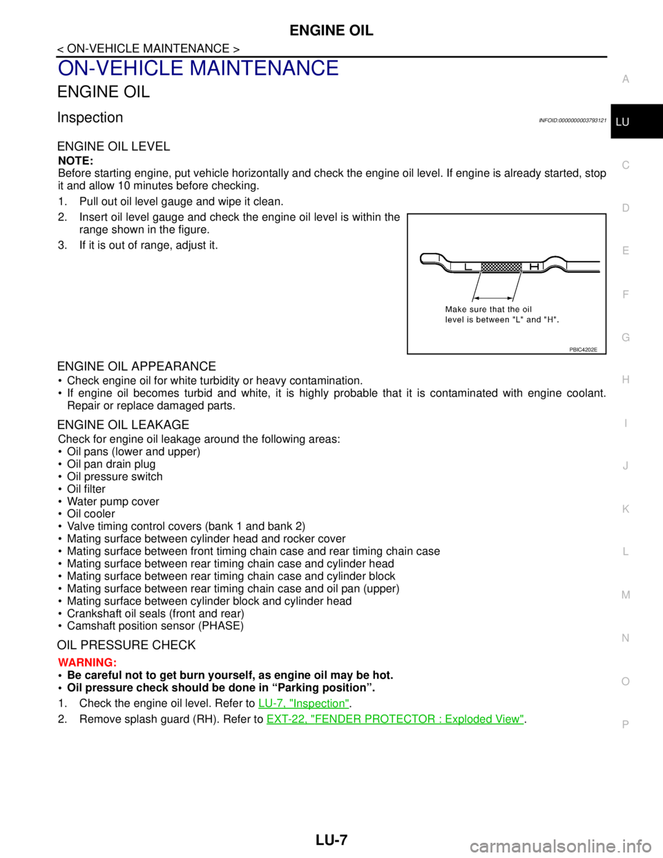
ENGINE OIL LEVEL
NOTE:
Before starting engine, put vehicle horizontally and check the engine oil level. If engine is already started, stop
it and allow 10 minutes before checking.
1. Pull out oil level gauge and wipe it clean.
2. Insert oil level gauge and check the engine oil level is within the
range shown in the figure.
3. If it is out of range, adjust it.
ENGINE OIL APPEARANCE
Check engine oil for white turbidity or heavy contamination.
If engine oil becomes turbid and white, it is highly probable that it is contaminated with engine coolant.
Repair or replace damaged parts.
ENGINE OIL LEAKAGE
Check for engine oil leakage around the following areas:
Oil pans (lower and upper)
Oil pan drain plug
Oil pressure switch
Oil filter
Water pump cover
Oil cooler
Valve timing control covers (bank 1 and bank 2)
Mating surface between cylinder head and rocker cover
Mating surface between front timing chain case and rear timing chain case
Mating surface between rear timing chain case and cylinder head
Mating surface between rear timing chain case and cylinder block
Mating surface between rear timing chain case and oil pan (upper)
Mating surface between cylinder block and cylinder head
Crankshaft oil seals (front and rear)
Camshaft position sensor (PHASE)
OIL PRESSURE CHECK
WARNING:
• Be careful not to get burn yourself, as engine oil may be hot.
Oil pressure check should be done in “Parking position”.
1. Check the engine oil level. Refer to LU-7, "
Inspection".
2. Remove splash guard (RH). Refer to EXT-22, "
FENDER PROTECTOR : Exploded View".
PBIC4202E