2008 NISSAN TEANA engine oil
[x] Cancel search: engine oilPage 1968 of 5121
OIL SEAL
EM-93
< DISASSEMBLY AND ASSEMBLY >
C
D
E
F
G
H
I
J
K
L
MA
EM
N
P O
OIL SEAL
VALVE OIL SEAL
VALVE OIL SEAL : Removal and InstallationINFOID:0000000003802286
REMOVAL
1. Remove camshaft relating to valve oil seal to be removed. Refer to EM-84, "Exploded View".
2. Remove valve lifters. Refer to EM-84, "
Exploded View".
3. Turn crankshaft until the cylinder requiring new oil seals is at TDC. This will prevent valve from dropping
into cylinder.
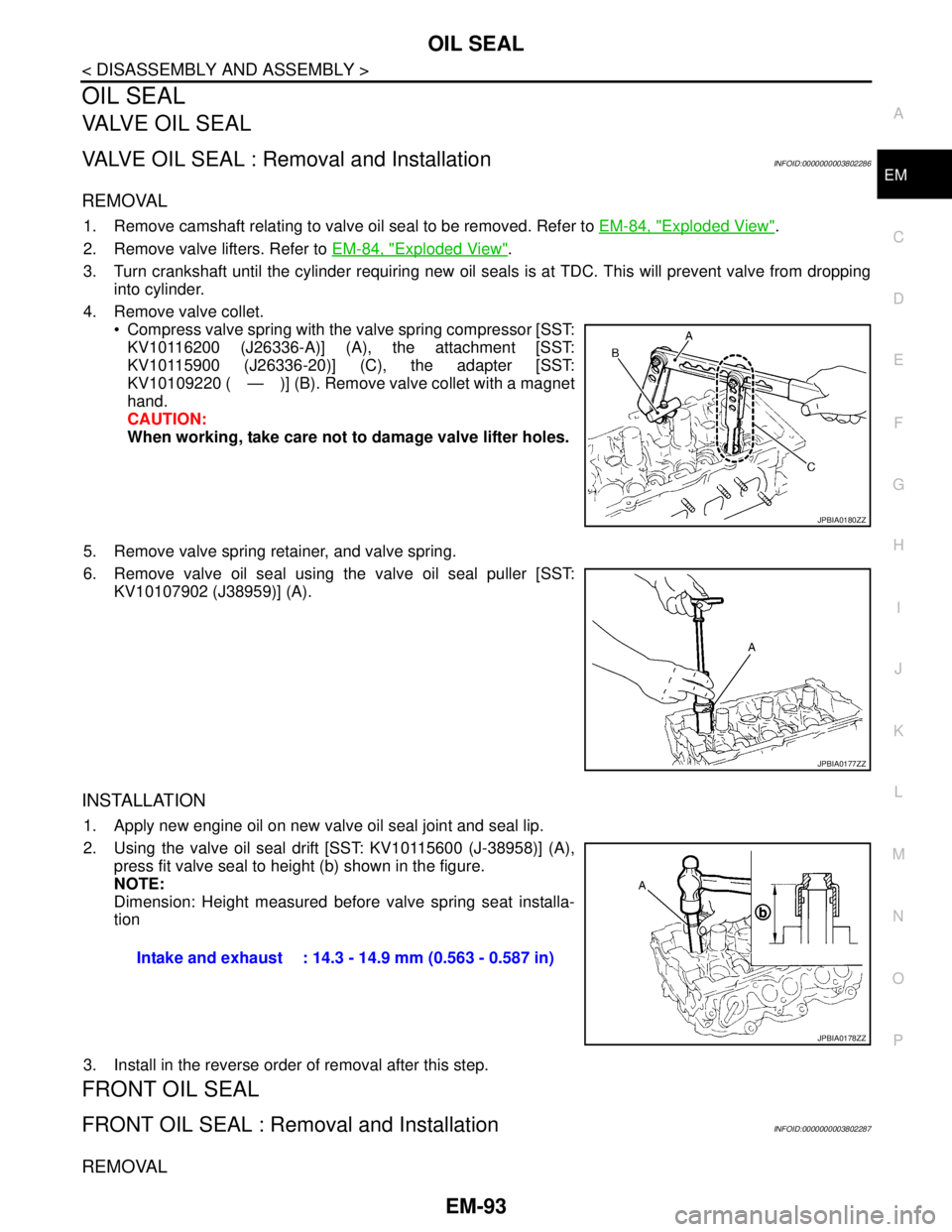
4. Remove valve collet.
Compress valve spring with the valve spring compressor [SST:
KV10116200 (J26336-A)] (A), the attachment [SST:
KV10115900 (J26336-20)] (C), the adapter [SST:
KV10109220 ( — )] (B). Remove valve collet with a magnet
hand.
CAUTION:
When working, take care not to damage valve lifter holes.
5. Remove valve spring retainer, and valve spring.
6. Remove valve oil seal using the valve oil seal puller [SST:
KV10107902 (J38959)] (A).
INSTALLATION
1. Apply new engine oil on new valve oil seal joint and seal lip.
2. Using the valve oil seal drift [SST: KV10115600 (J-38958)] (A),
press fit valve seal to height (b) shown in the figure.
NOTE:
Dimension: Height measured before valve spring seat installa-
tion
3. Install in the reverse order of removal after this step.
FRONT OIL SEAL
FRONT OIL SEAL : Removal and InstallationINFOID:0000000003802287
REMOVAL
JPBIA0180ZZ
JPBIA0177ZZ
Intake and exhaust : 14.3 - 14.9 mm (0.563 - 0.587 in)
JPBIA0178ZZ
Page 1969 of 5121
EM-94
< DISASSEMBLY AND ASSEMBLY >
OIL SEAL
1. Remove the following parts:
Road wheel and tire (RH)
Splash guard (RH): Refer to EXT-22, "
FENDER PROTECTOR : Exploded View".
Drive belt: Refer to EM-12, "
Removal and Installation".
Crankshaft pulley: Refer to EM-52, "
Exploded View".
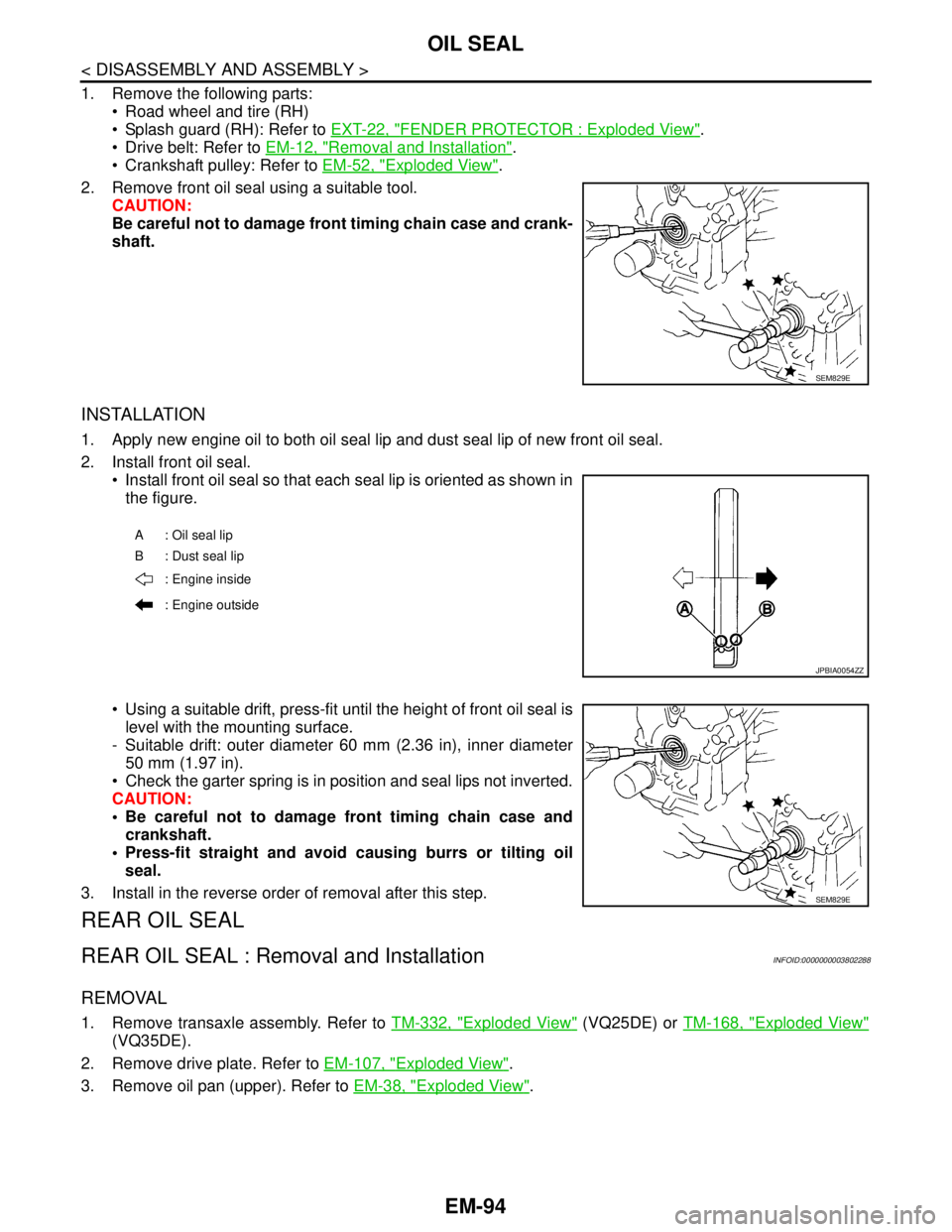
2. Remove front oil seal using a suitable tool.
CAUTION:
Be careful not to damage front timing chain case and crank-
shaft.
INSTALLATION
1. Apply new engine oil to both oil seal lip and dust seal lip of new front oil seal.
2. Install front oil seal.
Install front oil seal so that each seal lip is oriented as shown in
the figure.
Using a suitable drift, press-fit until the height of front oil seal is
level with the mounting surface.
- Suitable drift: outer diameter 60 mm (2.36 in), inner diameter
50 mm (1.97 in).
Check the garter spring is in position and seal lips not inverted.
CAUTION:
Be careful not to damage front timing chain case and
crankshaft.
Press-fit straight and avoid causing burrs or tilting oil
seal.
3. Install in the reverse order of removal after this step.
REAR OIL SEAL
REAR OIL SEAL : Removal and InstallationINFOID:0000000003802288
REMOVAL
1. Remove transaxle assembly. Refer to TM-332, "Exploded View" (VQ25DE) or TM-168, "Exploded View"
(VQ35DE).
2. Remove drive plate. Refer to EM-107, "
Exploded View".
3. Remove oil pan (upper). Refer to EM-38, "
Exploded View".
SEM829E
A: Oil seal lip
B : Dust seal lip
: Engine inside
: Engine outside
JPBIA0054ZZ
SEM829E
Page 1970 of 5121
OIL SEAL
EM-95
< DISASSEMBLY AND ASSEMBLY >
C
D
E
F
G
H
I
J
K
L
MA
EM
N
P O
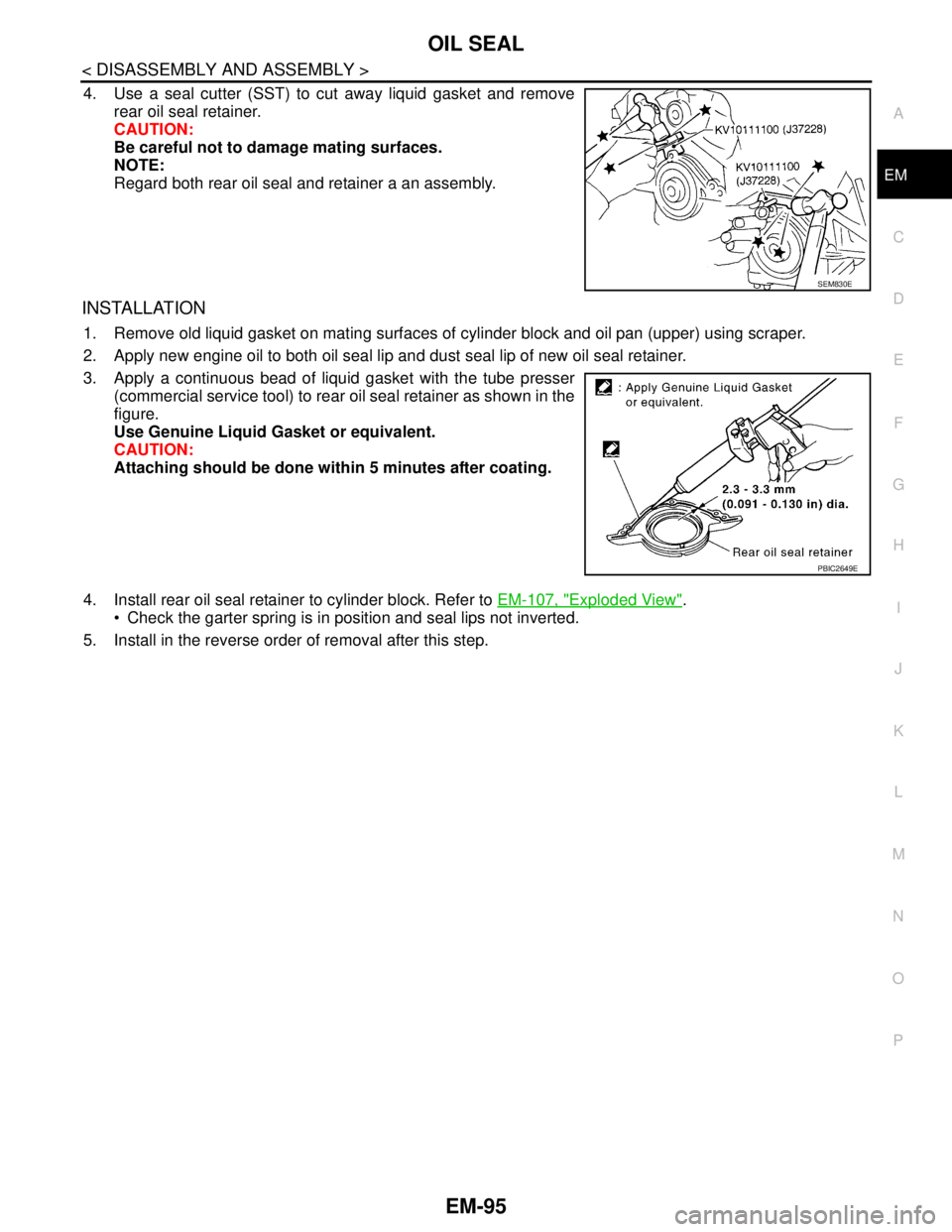
4. Use a seal cutter (SST) to cut away liquid gasket and remove
rear oil seal retainer.
CAUTION:
Be careful not to damage mating surfaces.
NOTE:
Regard both rear oil seal and retainer a an assembly.
INSTALLATION
1. Remove old liquid gasket on mating surfaces of cylinder block and oil pan (upper) using scraper.
2. Apply new engine oil to both oil seal lip and dust seal lip of new oil seal retainer.
3. Apply a continuous bead of liquid gasket with the tube presser
(commercial service tool) to rear oil seal retainer as shown in the
figure.
Use Genuine Liquid Gasket or equivalent.
CAUTION:
Attaching should be done within 5 minutes after coating.
4. Install rear oil seal retainer to cylinder block. Refer to EM-107, "
Exploded View".
Check the garter spring is in position and seal lips not inverted.
5. Install in the reverse order of removal after this step.
SEM830E
PBIC2649E
Page 1974 of 5121
CYLINDER HEAD
EM-99
< DISASSEMBLY AND ASSEMBLY >
C
D
E
F
G
H
I
J
K
L
MA
EM
N
P O
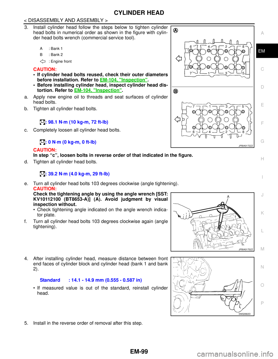
3. Install cylinder head follow the steps below to tighten cylinder
head bolts in numerical order as shown in the figure with cylin-
der head bolts wrench (commercial service tool).
CAUTION:
If cylinder head bolts reused, check their outer diameters
before installation. Refer to EM-104, "
Inspection".
Before installing cylinder head, inspect cylinder head dis-
tortion. Refer to EM-104, "
Inspection".
a. Apply new engine oil to threads and seat surfaces of cylinder
head bolts.
b. Tighten all cylinder head bolts.
c. Completely loosen all cylinder head bolts.
CAUTION:
In step “c”, loosen bolts in reverse order of that indicated in the figure.
d. Tighten all cylinder head bolts.
e. Turn all cylinder head bolts 103 degrees clockwise (angle tightening).
CAUTION:
Check the tightening angle by using the angle wrench [SST:
KV10112100 (BT8653-A)] (A). Avoid judgment by visual
inspection without.
Check tightening angle indicated on the angle wrench indica-
tor plate.
f. Turn all cylinder head bolts 103 degrees clockwise again (angle
tightening).
4. After installing cylinder head, measure distance between front
end faces of cylinder block and cylinder head (bank 1 and bank
2).
If measured value is out of the standard, reinstall cylinder
head.
5. Install in the reverse order of removal after this step.
A: Bank 1
B: Bank 2
: Engine front
: 98.1 N·m (10 kg-m, 72 ft-lb)
: 0 N·m (0 kg-m, 0 ft-lb)
: 39.2 N·m (4.0 kg-m, 29 ft-lb)
JPBIA0172ZZ
JPBIA0175ZZ
Standard : 14.1 - 14.9 mm (0.555 - 0.587 in)
EMQ0662D
Page 1978 of 5121
CYLINDER HEAD
EM-103
< DISASSEMBLY AND ASSEMBLY >
C
D
E
F
G
H
I
J
K
L
MA
EM
N
P O
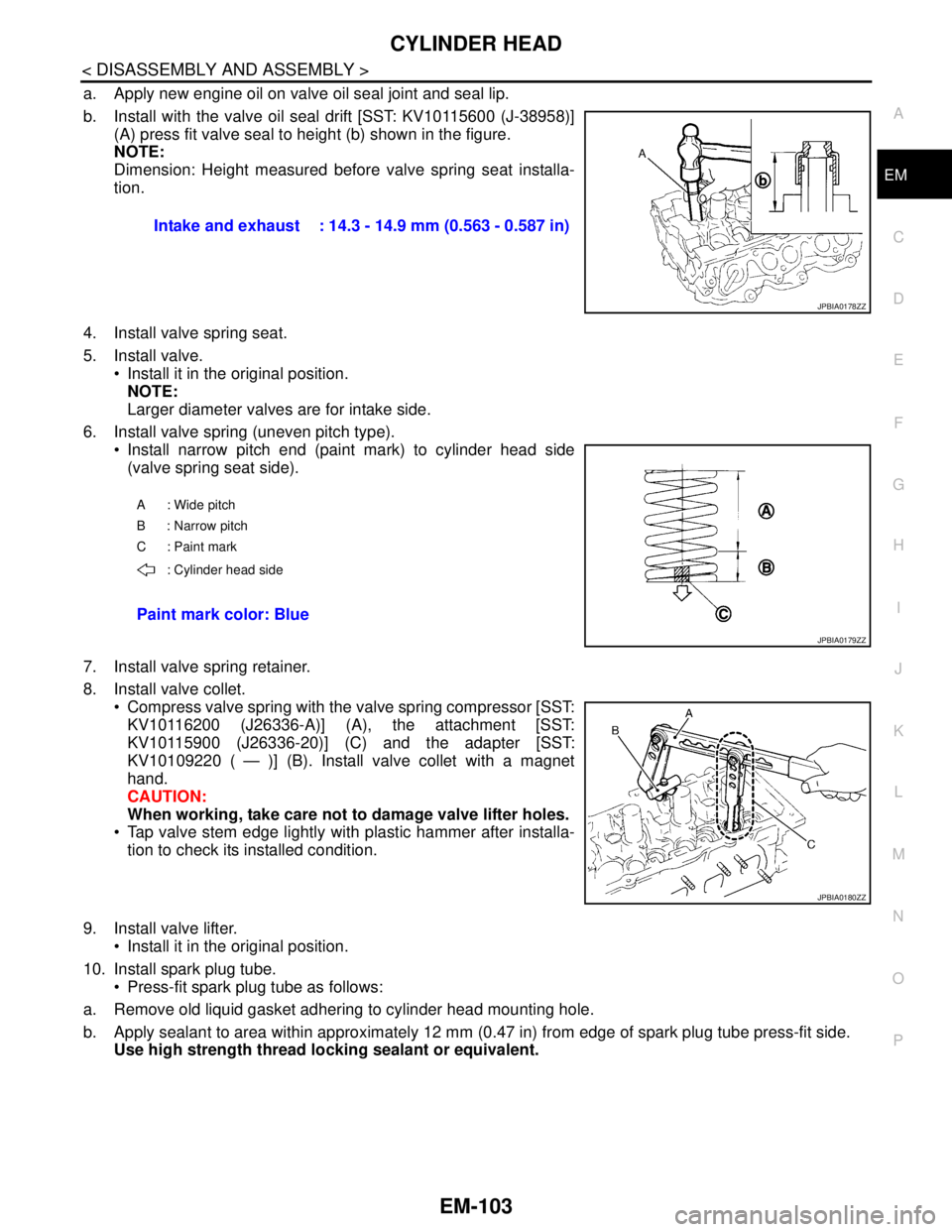
a. Apply new engine oil on valve oil seal joint and seal lip.
b. Install with the valve oil seal drift [SST: KV10115600 (J-38958)]
(A) press fit valve seal to height (b) shown in the figure.
NOTE:
Dimension: Height measured before valve spring seat installa-
tion.
4. Install valve spring seat.
5. Install valve.
Install it in the original position.
NOTE:
Larger diameter valves are for intake side.
6. Install valve spring (uneven pitch type).
Install narrow pitch end (paint mark) to cylinder head side
(valve spring seat side).
7. Install valve spring retainer.
8. Install valve collet.
Compress valve spring with the valve spring compressor [SST:
KV10116200 (J26336-A)] (A), the attachment [SST:
KV10115900 (J26336-20)] (C) and the adapter [SST:
KV10109220 ( — )] (B). Install valve collet with a magnet
hand.
CAUTION:
When working, take care not to damage valve lifter holes.
Tap valve stem edge lightly with plastic hammer after installa-
tion to check its installed condition.
9. Install valve lifter.
Install it in the original position.
10. Install spark plug tube.
Press-fit spark plug tube as follows:
a. Remove old liquid gasket adhering to cylinder head mounting hole.
b. Apply sealant to area within approximately 12 mm (0.47 in) from edge of spark plug tube press-fit side.
Use high strength thread locking sealant or equivalent. Intake and exhaust : 14.3 - 14.9 mm (0.563 - 0.587 in)
JPBIA0178ZZ
A : Wide pitch
B : Narrow pitch
C : Paint mark
: Cylinder head side
Paint mark color: Blue
JPBIA0179ZZ
JPBIA0180ZZ
Page 1979 of 5121
EM-104
< DISASSEMBLY AND ASSEMBLY >
CYLINDER HEAD
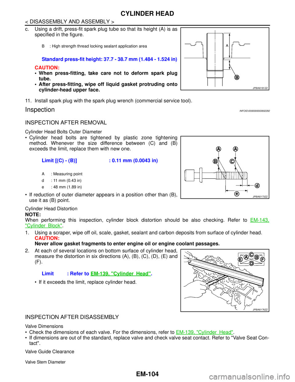
c. Using a drift, press-fit spark plug tube so that its height (A) is as
specified in the figure.
CAUTION:
When press-fitting, take care not to deform spark plug
tube.
After press-fitting, wipe off liquid gasket protruding onto
cylinder-head upper face.
11. Install spark plug with the spark plug wrench (commercial service tool).
InspectionINFOID:0000000003802292
INSPECTION AFTER REMOVAL
Cylinder Head Bolts Outer Diameter
Cylinder head bolts are tightened by plastic zone tightening
method. Whenever the size difference between (C) and (B)
exceeds the limit, replace them with new one.
If reduction of outer diameter appears in a position other than (B),
use it as (B) point.
Cylinder Head Distortion
NOTE:
When performing this inspection, cylinder block distortion should be also checking. Refer to EM-143,
"CylinderBlock".
1. Using a scraper, wipe off oil, scale, gasket, sealant and carbon deposits from surface of cylinder head.
CAUTION:
Never allow gasket fragments to enter engine oil or engine coolant passages.
2. At each of several locations on bottom surface of cylinder head,
measure the distortion in six directions (A), (B), (C), (D), (E) and
(F).
If it exceeds the limit, replace cylinder head.
INSPECTION AFTER DISASSEMBLY
Valve Dimensions
Check the dimensions of each valve. For the dimensions, refer to EM-139, "CylinderHead".
If dimensions are out of the standard, replace valve and check valve seat contact. Refer to "Valve Seat Con-
tact".
Valve Guide Clearance
Valve Stem Diameter
B : High strength thread locking sealant application area
Standard press-fit height: 37.7 - 38.7 mm (1.484 - 1.524 in)
JPBIA0181ZZ
Limit [(C) - (B)] : 0.11 mm (0.0043 in)
A : Measuring point
d : 11 mm (0.43 in)
e : 48 mm (1.89 in)
JPBIA0173ZZ
Limit : Refer to EM-139, "CylinderHead".
JPBIA0176ZZ
Page 1981 of 5121
EM-106
< DISASSEMBLY AND ASSEMBLY >
CYLINDER HEAD
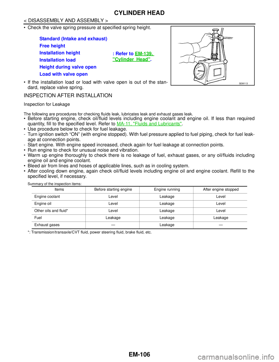
Check the valve spring pressure at specified spring height.
If the installation load or load with valve open is out of the stan-
dard, replace valve spring.
INSPECTION AFTER INSTALLATION
Inspection for Leakage
The following are procedures for checking fluids leak, lubricates leak and exhaust gases leak.
Before starting engine, check oil/fluid levels including engine coolant and engine oil. If less than required
quantity, fill to the specified level. Refer to MA-11, "
Fluids and Lubricants".
Use procedure below to check for fuel leakage.
- Turn ignition switch “ON” (with engine stopped). With fuel pressure applied to fuel piping, check for fuel leak-
age at connection points.
- Start engine. With engine speed increased, check again for fuel leakage at connection points.
Run engine to check for unusual noise and vibration.
Warm up engine thoroughly to check there is no leakage of fuel, exhaust gases, or any oil/fluids including
engine oil and engine coolant.
Bleed air from lines and hoses of applicable lines, such as in cooling system.
After cooling down engine, again check oil/fluid levels including engine oil and engine coolant. Refill to the
specified level, if necessary.
Summary of the inspection items:
*: Transmission/transaxle/CVT fluid, power steering fluid, brake fluid, etc.
Standard (Intake and exhaust)
: Refer to EM-139,
"CylinderHead". Free height
Installation height
Installation load
Height during valve open
Load with valve open
SEM113
Items Before starting engine Engine running After engine stopped
Engine coolant Level Leakage Level
Engine oil Level Leakage Level
Other oils and fluid* Level Leakage Level
Fuel Leakage Leakage Leakage
Exhaust gases — Leakage —
Page 1987 of 5121
EM-112
< DISASSEMBLY AND ASSEMBLY >
CYLINDER BLOCK
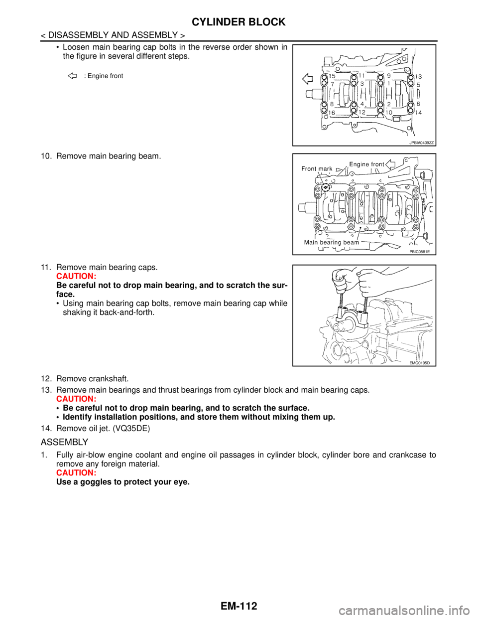
Loosen main bearing cap bolts in the reverse order shown in
the figure in several different steps.
10. Remove main bearing beam.
11. Remove main bearing caps.
CAUTION:
Be careful not to drop main bearing, and to scratch the sur-
face.
Using main bearing cap bolts, remove main bearing cap while
shaking it back-and-forth.
12. Remove crankshaft.
13. Remove main bearings and thrust bearings from cylinder block and main bearing caps.
CAUTION:
Be careful not to drop main bearing, and to scratch the surface.
Identify installation positions, and store them without mixing them up.
14. Remove oil jet. (VQ35DE)
ASSEMBLY
1. Fully air-blow engine coolant and engine oil passages in cylinder block, cylinder bore and crankcase to
remove any foreign material.
CAUTION:
Use a goggles to protect your eye.
: Engine front
JPBIA0439ZZ
PBIC0881E
EMQ0195D