Page 1887 of 5121
EM-12
< ON-VEHICLE MAINTENANCE >
DRIVE BELT
ON-VEHICLE MAINTENANCE
DRIVE BELT
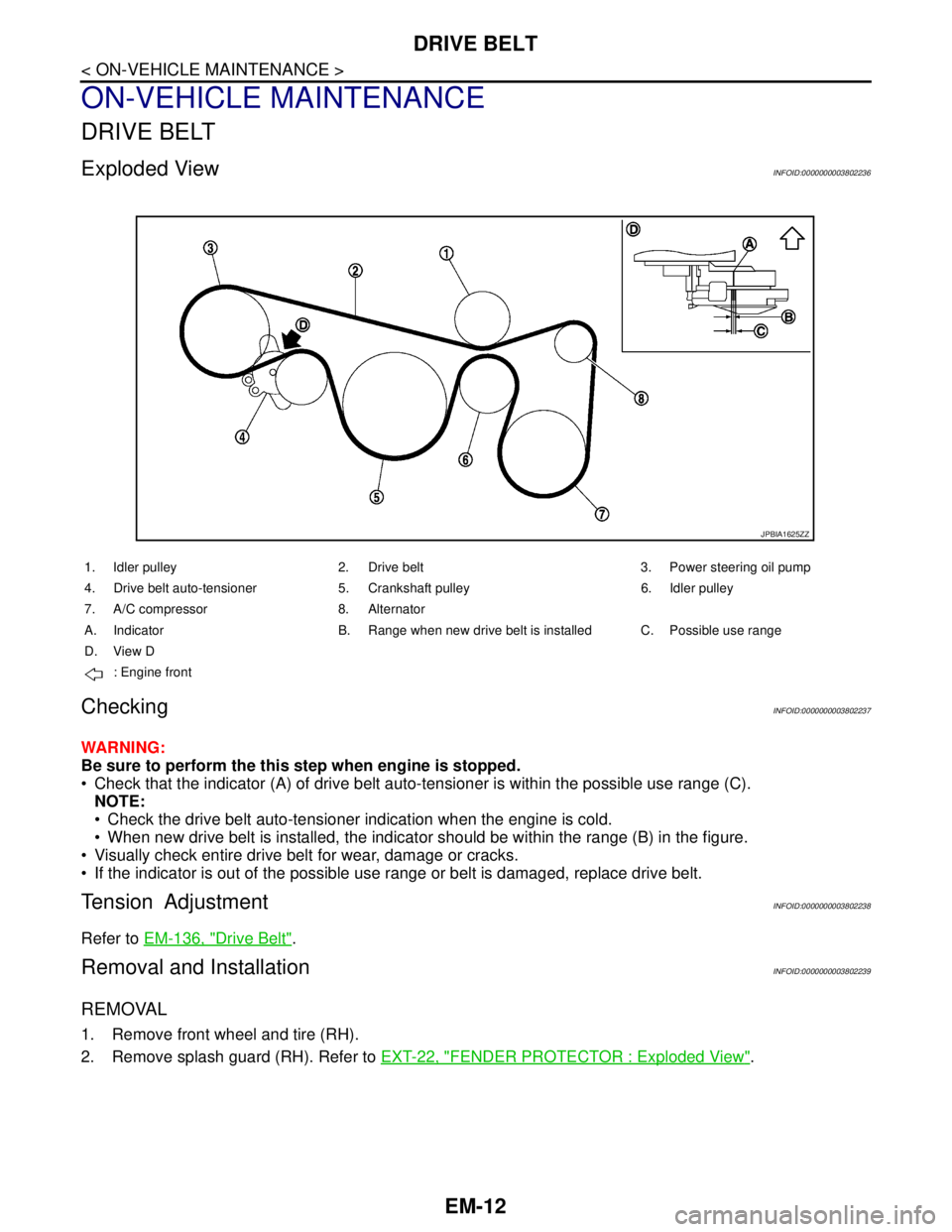
Exploded ViewINFOID:0000000003802236
CheckingINFOID:0000000003802237
WARNING:
Be sure to perform the this step when engine is stopped.
Check that the indicator (A) of drive belt auto-tensioner is within the possible use range (C).
NOTE:
Check the drive belt auto-tensioner indication when the engine is cold.
When new drive belt is installed, the indicator should be within the range (B) in the figure.
Visually check entire drive belt for wear, damage or cracks.
If the indicator is out of the possible use range or belt is damaged, replace drive belt.
Tension AdjustmentINFOID:0000000003802238
Refer to EM-136, "Drive Belt".
Removal and InstallationINFOID:0000000003802239
REMOVAL
1. Remove front wheel and tire (RH).
2. Remove splash guard (RH). Refer to EXT-22, "
FENDER PROTECTOR : Exploded View".
JPBIA1625ZZ
1. Idler pulley 2. Drive belt 3. Power steering oil pump
4. Drive belt auto-tensioner 5. Crankshaft pulley 6. Idler pulley
7. A/C compressor 8. Alternator
A. Indicator B. Range when new drive belt is installed C. Possible use range
D. View D
: Engine front
Page 1888 of 5121
DRIVE BELT
EM-13
< ON-VEHICLE MAINTENANCE >
C
D
E
F
G
H
I
J
K
L
MA
EM
N
P O
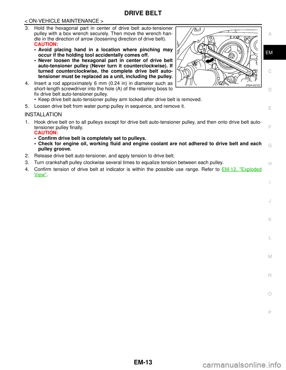
3. Hold the hexagonal part in center of drive belt auto-tensioner
pulley with a box wrench securely. Then move the wrench han-
dle in the direction of arrow (loosening direction of drive belt).
CAUTION:
Avoid placing hand in a location where pinching may
occur if the holding tool accidentally comes off.
Never loosen the hexagonal part in center of drive belt
auto-tensioner pulley (Never turn it counterclockwise). If
turned counterclockwise, the complete drive belt auto-
tensioner must be replaced as a unit, including the pulley.
4. Insert a rod approximately 6 mm (0.24 in) in diameter such as
short-length screwdriver into the hole (A) of the retaining boss to
fix drive belt auto-tensioner pulley.
Keep drive belt auto-tensioner pulley arm locked after drive belt is removed.
5. Loosen drive belt from water pump pulley in sequence, and remove it.
INSTALLATION
1. Hook drive belt on to all pulleys except for drive belt auto-tensioner pulley, and then onto drive belt auto-
tensioner pulley finally.
CAUTION:
Confirm drive belt is completely set to pulleys.
Check for engine oil, working fluid and engine coolant are not adhered to drive belt and each
pulley groove.
2. Release drive belt auto-tensioner, and apply tension to drive belt.
3. Turn crankshaft pulley clockwise several times to equalize tension between each pulley.
4. Confirm tension of drive belt at indicator is within the possible use range. Refer to EM-12, "
Exploded
View".
JPBIA1627ZZ
Page 1890 of 5121
SPARK PLUG
EM-15
< ON-VEHICLE MAINTENANCE >
C
D
E
F
G
H
I
J
K
L
MA
EM
N
P O
SPARK PLUG
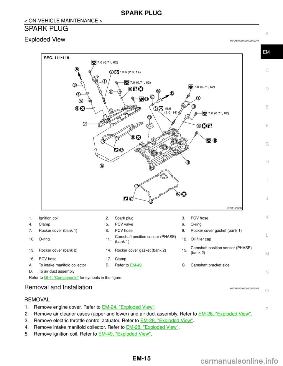
Exploded ViewINFOID:0000000003802241
Removal and InstallationINFOID:0000000003802242
REMOVAL
1. Remove engine cover. Refer to EM-24, "Exploded View".
2. Remove air cleaner cases (upper and lower) and air duct assembly. Refer to EM-26, "
Exploded View".
3. Remove electric throttle control actuator. Refer to EM-28, "
Exploded View".
4. Remove intake manifold collector. Refer to EM-28, "
Exploded View".
5. Remove ignition coil. Refer to EM-49, "
Exploded View".
1. Ignition coil 2. Spark plug 3. PCV hose
4. Clamp 5. PCV valve 6. O-ring
7. Rocker cover (bank 1) 8. PCV hose 9. Rocker cover gasket (bank 1)
10. O-ring 11.Camshaft position sensor (PHASE)
(bank 1)12. Oil filler cap
13. Rocker cover (bank 2) 14. Rocker cover gasket (bank 2) 15.Camshaft position sensor (PHASE)
(bank 2)
16. PCV hose 17. Clamp
A. To intake manifold collector B. Refer to EM-49
C. Camshaft bracket side
D. To air duct assembly
Refer to GI-4, "
Components" for symbols in the figure.
JPBIA1637GB
Page 1897 of 5121
EM-22
< ON-VEHICLE MAINTENANCE >
COMPRESSION PRESSURE
COMPRESSION PRESSURE
InspectionINFOID:0000000003802245
1. Warm up engine thoroughly. Then, stop it.
2. Release fuel pressure. Refer to EC-411, "
Inspection".
3. Disconnect fuel pump fuse to avoid fuel injection during measurement. Refer to EC-20,
"ComponentPartsLocation".
4. Remove engine cover. Refer to EM-24, "
Exploded View".
5. Remove ignition coil and spark plug from each cylinder. Refer to EM-49, "
Exploded View".
6. Connect engine tachometer (not required in use of CONSULT-III).
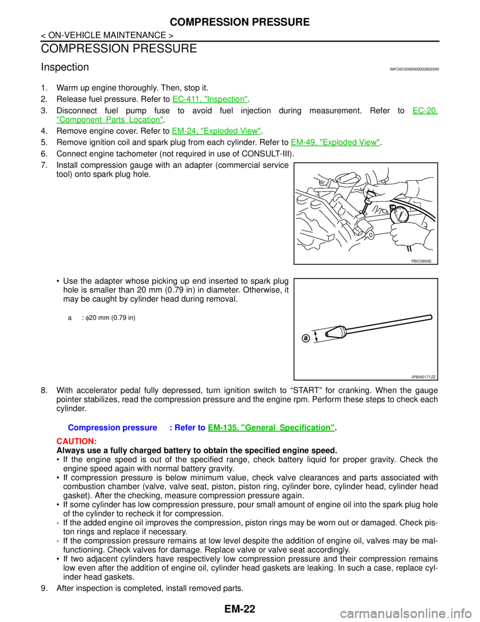
7. Install compression gauge with an adapter (commercial service
tool) onto spark plug hole.
Use the adapter whose picking up end inserted to spark plug
hole is smaller than 20 mm (0.79 in) in diameter. Otherwise, it
may be caught by cylinder head during removal.
8. With accelerator pedal fully depressed, turn ignition switch to “START” for cranking. When the gauge
pointer stabilizes, read the compression pressure and the engine rpm. Perform these steps to check each
cylinder.
CAUTION:
Always use a fully charged battery to obtain the specified engine speed.
If the engine speed is out of the specified range, check battery liquid for proper gravity. Check the
engine speed again with normal battery gravity.
If compression pressure is below minimum value, check valve clearances and parts associated with
combustion chamber (valve, valve seat, piston, piston ring, cylinder bore, cylinder head, cylinder head
gasket). After the checking, measure compression pressure again.
If some cylinder has low compression pressure, pour small amount of engine oil into the spark plug hole
of the cylinder to recheck it for compression.
- If the added engine oil improves the compression, piston rings may be worn out or damaged. Check pis-
ton rings and replace if necessary.
- If the compression pressure remains at low level despite the addition of engine oil, valves may be mal-
functioning. Check valves for damage. Replace valve or valve seat accordingly.
If two adjacent cylinders have respectively low compression pressure and their compression remains
low even after the addition of engine oil, cylinder head gaskets are leaking. In such a case, replace cyl-
inder head gaskets.
9. After inspection is completed, install removed parts.
PBIC0900E
a: φ20 mm (0.79 in)
JPBIA0171ZZ
Compression pressure : Refer to EM-135, "GeneralSpecification".
Page 1909 of 5121
EM-34
< ON-VEHICLE REPAIR >
EXHAUST MANIFOLD AND THREE WAY CATALYST
EXHAUST MANIFOLD AND THREE WAY CATALYST
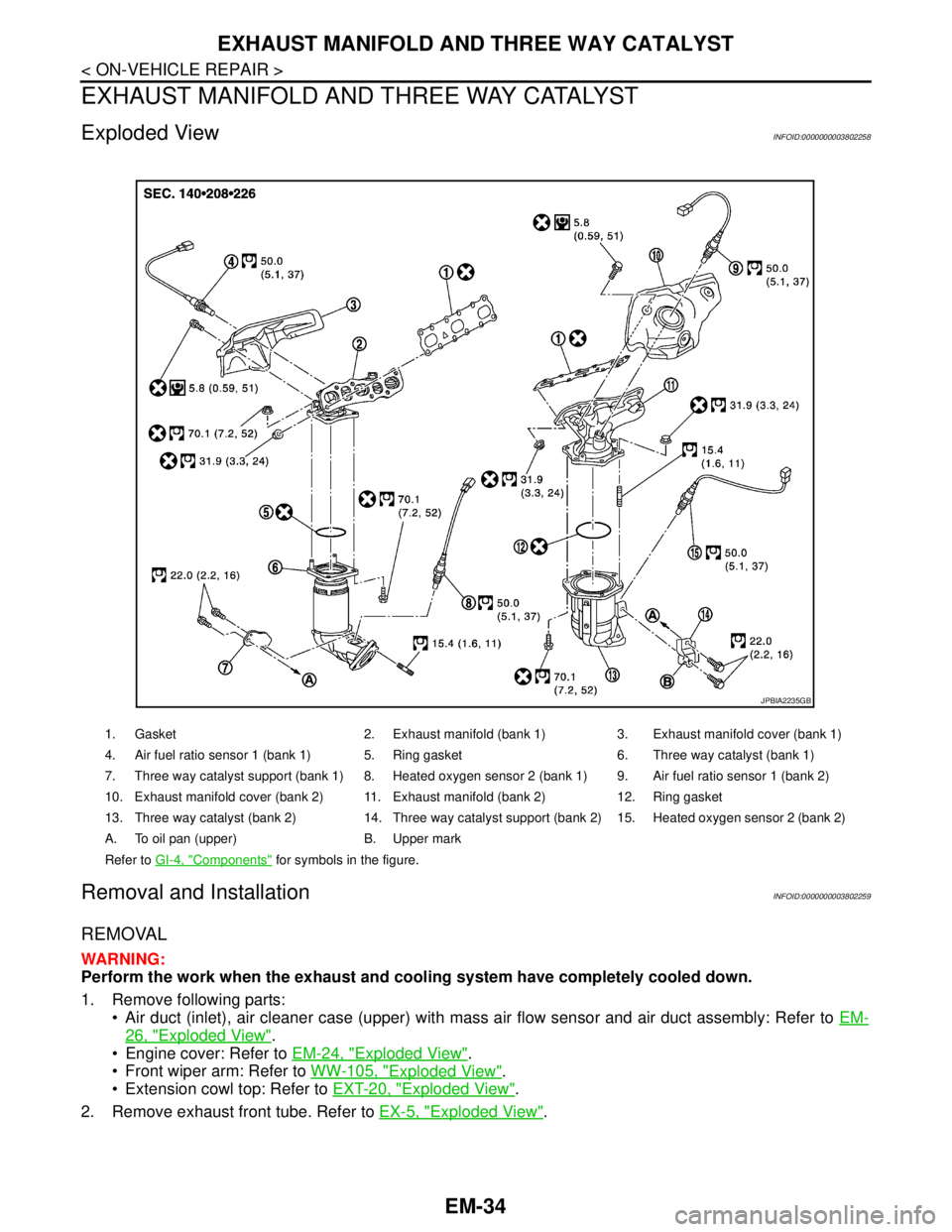
Exploded ViewINFOID:0000000003802258
Removal and InstallationINFOID:0000000003802259
REMOVAL
WARNING:
Perform the work when the exhaust and cooling system have completely cooled down.
1. Remove following parts:
Air duct (inlet), air cleaner case (upper) with mass air flow sensor and air duct assembly: Refer to EM-
26, "Exploded View".
Engine cover: Refer to EM-24, "
Exploded View".
Front wiper arm: Refer to WW-105, "
Exploded View".
Extension cowl top: Refer to EXT-20, "
Exploded View".
2. Remove exhaust front tube. Refer to EX-5, "
Exploded View".
1. Gasket 2. Exhaust manifold (bank 1) 3. Exhaust manifold cover (bank 1)
4. Air fuel ratio sensor 1 (bank 1) 5. Ring gasket 6. Three way catalyst (bank 1)
7. Three way catalyst support (bank 1) 8. Heated oxygen sensor 2 (bank 1) 9. Air fuel ratio sensor 1 (bank 2)
10. Exhaust manifold cover (bank 2) 11. Exhaust manifold (bank 2) 12. Ring gasket
13. Three way catalyst (bank 2) 14. Three way catalyst support (bank 2) 15. Heated oxygen sensor 2 (bank 2)
A. To oil pan (upper) B. Upper mark
Refer to GI-4, "
Components" for symbols in the figure.
JPBIA2235GB
Page 1911 of 5121
EM-36
< ON-VEHICLE REPAIR >
EXHAUST MANIFOLD AND THREE WAY CATALYST
Cover engine openings to avoid entry of foreign materials.
INSTALLATION
Note the following, and install in the reverse order of removal.
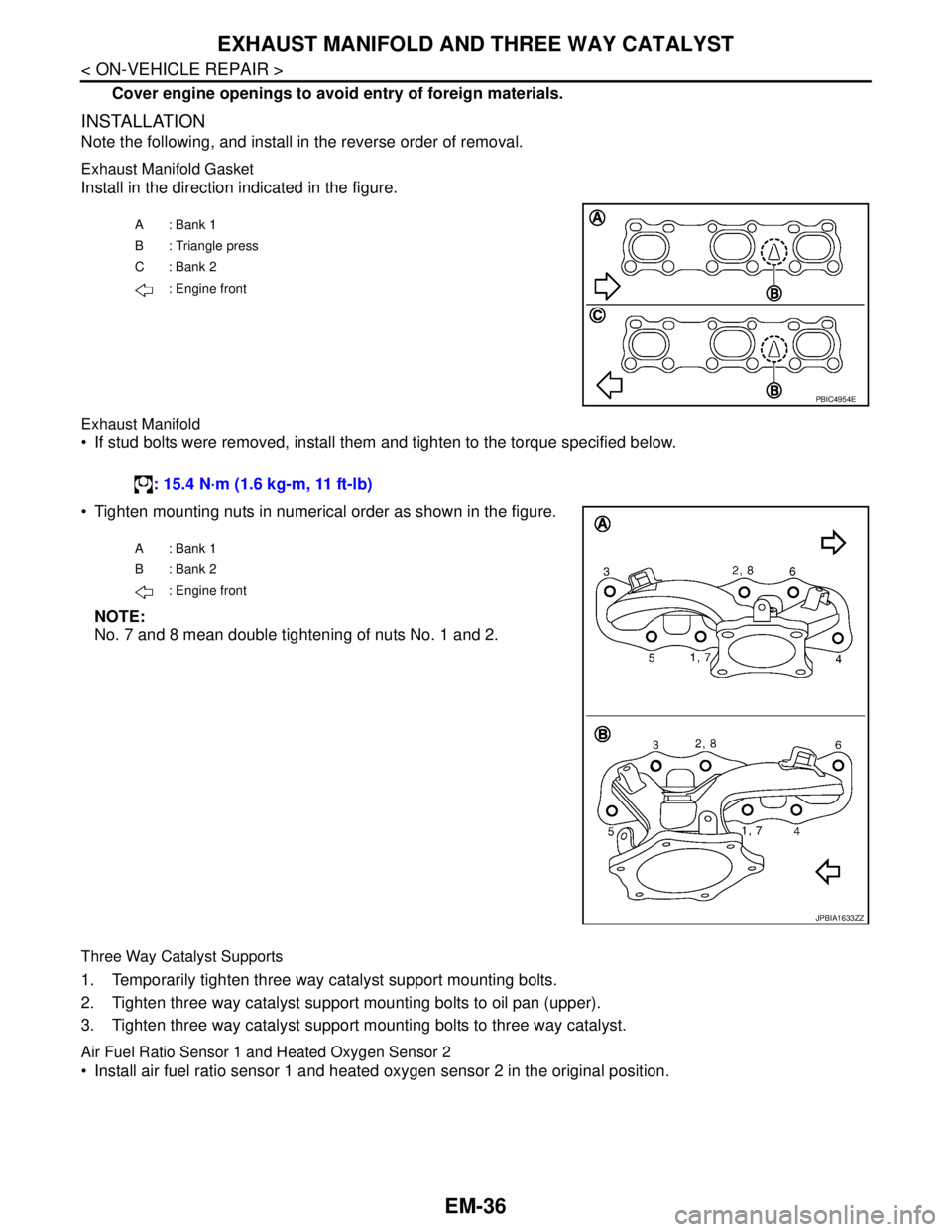
Exhaust Manifold Gasket
Install in the direction indicated in the figure.
Exhaust Manifold
If stud bolts were removed, install them and tighten to the torque specified below.
Tighten mounting nuts in numerical order as shown in the figure.
NOTE:
No. 7 and 8 mean double tightening of nuts No. 1 and 2.
Three Way Catalyst Supports
1. Temporarily tighten three way catalyst support mounting bolts.
2. Tighten three way catalyst support mounting bolts to oil pan (upper).
3. Tighten three way catalyst support mounting bolts to three way catalyst.
Air Fuel Ratio Sensor 1 and Heated Oxygen Sensor 2
Install air fuel ratio sensor 1 and heated oxygen sensor 2 in the original position.
A: Bank 1
B : Triangle press
C: Bank 2
: Engine front
PBIC4954E
: 15.4 N·m (1.6 kg-m, 11 ft-lb)
A: Bank 1
B: Bank 2
: Engine front
JPBIA1633ZZ
Page 1913 of 5121
EM-38
< ON-VEHICLE REPAIR >
OIL PAN AND OIL STRAINER
OIL PAN AND OIL STRAINER
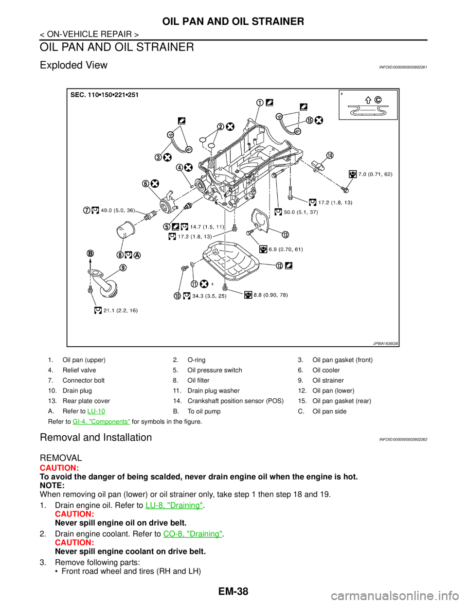
Exploded ViewINFOID:0000000003802261
Removal and InstallationINFOID:0000000003802262
REMOVAL
CAUTION:
To avoid the danger of being scalded, never drain engine oil when the engine is hot.
NOTE:
When removing oil pan (lower) or oil strainer only, take step 1 then step 18 and 19.
1. Drain engine oil. Refer to LU-8, "
Draining".
CAUTION:
Never spill engine oil on drive belt.
2. Drain engine coolant. Refer to CO-8, "
Draining".
CAUTION:
Never spill engine coolant on drive belt.
3. Remove following parts:
Front road wheel and tires (RH and LH)
1. Oil pan (upper) 2. O-ring 3. Oil pan gasket (front)
4. Relief valve 5. Oil pressure switch 6. Oil cooler
7. Connector bolt 8. Oil filter 9. Oil strainer
10. Drain plug 11. Drain plug washer 12. Oil pan (lower)
13. Rear plate cover 14. Crankshaft position sensor (POS) 15. Oil pan gasket (rear)
A. Refer to LU-10
B. To oil pump C. Oil pan side
Refer to GI-4, "
Components" for symbols in the figure.
JPBIA1636GB
Page 1914 of 5121
OIL PAN AND OIL STRAINER
EM-39
< ON-VEHICLE REPAIR >
C
D
E
F
G
H
I
J
K
L
MA
EM
N
P O
Splash guard (RH and LH): Refer to EXT-22, "FENDER PROTECTOR : Exploded View".
Exhaust front tube: Refer to EX-5, "
Exploded View".
Drive belt: Refer to EM-12, "
Removal and Installation".
4. Remove A/C compressor with piping connected, and temporarily secure it to aside. Refer to HA-36,
"Exploded View".
5. Remove oil level gauge. Refer to EM-96, "
Exploded View".
6. Remove front drive shaft (RH). Refer to FAX-16, "
Exploded View".
7. Remove three way catalyst (bank 1 and bank 2) from exhaust manifolds (bank 1 and bank 2). Refer to
EM-34, "
Exploded View".
8. Remove oil pressure switch.
9. Remove oil filter. Refer to LU-10, "
Removal and Installation".
10. Remove oil cooler and water pipes. Refer to LU-11, "
Exploded View".
11. Support transaxle assembly with a suitable jack.
CAUTION:
When setting the transmission jack, be careful not to allow it to collide against the drain plug.
12. Support front suspension member with a suitable jack.
13. Remove engine mounting insulator (rear). Refer to EM-67, "
Exploded View".
14. Remove engine mounting insulator (LH) mounting bolts from transaxle. Refer to EM-67, "
Exploded View".
15. Remove rear torque rod through bolts from rear torque rod bracket. Refer to EM-67, "
Exploded View".
16. Remove member stay, front suspension member fixing bolts and nuts. Refer to FSU-16, "
Exploded View".
17. Lower the jack for the front suspension member to the height.
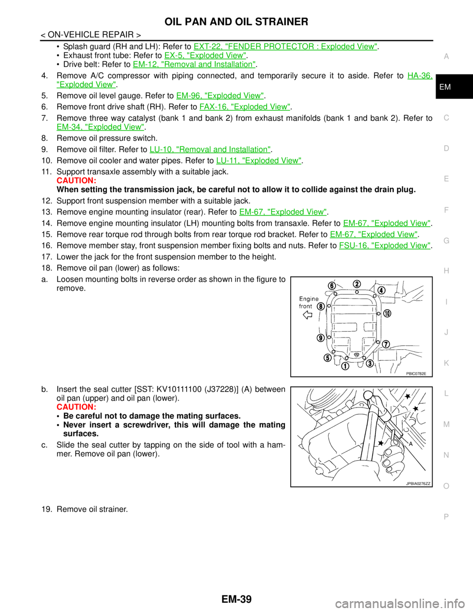
18. Remove oil pan (lower) as follows:
a. Loosen mounting bolts in reverse order as shown in the figure to
remove.
b. Insert the seal cutter [SST: KV10111100 (J37228)] (A) between
oil pan (upper) and oil pan (lower).
CAUTION:
Be careful not to damage the mating surfaces.
Never insert a screwdriver, this will damage the mating
surfaces.
c. Slide the seal cutter by tapping on the side of tool with a ham-
mer. Remove oil pan (lower).
19. Remove oil strainer.
PBIC0782E
JPBIA0276ZZ