2008 NISSAN TEANA engine oil
[x] Cancel search: engine oilPage 1864 of 5121
![NISSAN TEANA 2008 Service Manual ENGINE CONTROL SYSTEM SYMPTOMS
EC-403
< SYMPTOM DIAGNOSIS >[VQ25DE, VQ35DE]
C
D
E
F
G
H
I
J
K
L
MA
EC
N
P O
1 - 6: The numbers refer to the order of inspection.Va l v e
mecha-
nismTiming chain
55555 NISSAN TEANA 2008 Service Manual ENGINE CONTROL SYSTEM SYMPTOMS
EC-403
< SYMPTOM DIAGNOSIS >[VQ25DE, VQ35DE]
C
D
E
F
G
H
I
J
K
L
MA
EC
N
P O
1 - 6: The numbers refer to the order of inspection.Va l v e
mecha-
nismTiming chain
55555](/manual-img/5/57391/w960_57391-1863.png)
ENGINE CONTROL SYSTEM SYMPTOMS
EC-403
< SYMPTOM DIAGNOSIS >[VQ25DE, VQ35DE]
C
D
E
F
G
H
I
J
K
L
MA
EC
N
P O
1 - 6: The numbers refer to the order of inspection.Va l v e
mecha-
nismTiming chain
55555 55 5EM-65
CamshaftEM-84
Intake valve timing controlEM-65
Intake valve
3EM-97
Exhaust valve
Exhaust Exhaust manifold/Tube/Muffler/
Gasket
55555 55 5EM-34
, EX-
4Three way catalyst
Lubrica-
tionOil pan/Oil strainer/Oil pump/Oil
filter/Oil gallery/Oil cooler
55555 55 5LU-7
, LU-
10, LU-11,
LU-13
Oil level (Low)/Filthy oilLU-7
Cooling
Radiator/Hose/Radiator filler cap
55555 55 45CO-12,
CO-12
Thermostat 5CO-23
Water pumpCO-18
Water galleryCO-2
Cooling fan
5CO-16
Coolant level (Low)/Contaminat-
ed coolantCO-8
NVIS (NISSAN Vehicle Immobilizer System —
NATS)11SEC-14
SYMPTOM
Reference
page
HARD/NO START/RESTART (EXCP. HA)
ENGINE STALL
HESITATION/SURGING/FLAT SPOT
SPARK KNOCK/DETONATION
LACK OF POWER/POOR ACCELERATION
HIGH IDLE/LOW IDLE
ROUGH IDLE/HUNTING
IDLING VIBRATION
SLOW/NO RETURN TO IDLE
OVERHEATS/WATER TEMPERATURE HIGH
EXCESSIVE FUEL CONSUMPTION
EXCESSIVE OIL CONSUMPTION
BATTERY DEAD (UNDER CHARGE)
Warranty symptom code AA AB AC AD AE AF AG AH AJ AK AL AM HA
Page 1866 of 5121
![NISSAN TEANA 2008 Service Manual PRECAUTIONS
EC-405
< PRECAUTION >[VQ25DE, VQ35DE]
C
D
E
F
G
H
I
J
K
L
MA
EC
N
P O
PRECAUTION
PRECAUTIONS
Precaution for Supplemental Restraint System (SRS) "AIR BAG" and "SEAT BELT
PRE-TENSIONER"
INF NISSAN TEANA 2008 Service Manual PRECAUTIONS
EC-405
< PRECAUTION >[VQ25DE, VQ35DE]
C
D
E
F
G
H
I
J
K
L
MA
EC
N
P O
PRECAUTION
PRECAUTIONS
Precaution for Supplemental Restraint System (SRS) "AIR BAG" and "SEAT BELT
PRE-TENSIONER"
INF](/manual-img/5/57391/w960_57391-1865.png)
PRECAUTIONS
EC-405
< PRECAUTION >[VQ25DE, VQ35DE]
C
D
E
F
G
H
I
J
K
L
MA
EC
N
P O
PRECAUTION
PRECAUTIONS
Precaution for Supplemental Restraint System (SRS) "AIR BAG" and "SEAT BELT
PRE-TENSIONER"
INFOID:0000000003960684
The Supplemental Restraint System such as “AIR BAG” and “SEAT BELT PRE-TENSIONER”, used along
with a front seat belt, helps to reduce the risk or severity of injury to the driver and front passenger for certain
types of collision. Information necessary to service the system safely is included in the “SRS AIRBAG” and
“SEAT BELT” of this Service Manual.
WARNING:
To avoid rendering the SRS inoperative, which could increase the risk of personal injury or death in
the event of a collision which would result in air bag inflation, all maintenance must be performed by
an authorized NISSAN/INFINITI dealer.
Improper maintenance, including incorrect removal and installation of the SRS, can lead to personal
injury caused by unintentional activation of the system. For removal of Spiral Cable and Air Bag
Module, see the “SRS AIRBAG”.
Never use electrical test equipment on any circuit related to the SRS unless instructed to in this Ser-
vice Manual. SRS wiring harnesses can be identified by yellow and/or orange harnesses or harness
connectors.
Precautions For Xenon Headlamp ServiceINFOID:0000000003856878
WARNING:
Comply with the following warnings to prevent any serious accident.
Disconnect the battery cable (negative terminal) or the power supply fuse before installing, remov-
ing, or touching the xenon headlamp (bulb included). The xenon headlamp contains high-voltage
generated parts.
Never work with wet hands.
Check the xenon headlamp ON-OFF status after assembling it to the vehicle. Never turn the xenon
headlamp ON in other conditions. Connect the power supply to the vehicle-side connector.
(Turning it ON outside the lamp case may cause fire or visual impairments.)
Never touch the bulb glass immediately after turning it OFF. It is extremely hot.
CAUTION:
Comply with the following cautions to prevent any error and malfunction.
Install the xenon bulb securely. (Insufficient bulb socket installation may melt the bulb, the connec-
tor, the housing, etc. by high-voltage leakage or corona discharge.)
Never perform HID circuit inspection with a tester.
Never touch the xenon bulb glass with hands. Never put oil and grease on it.
Dispose of the used xenon bulb after packing it in thick vinyl without breaking it.
Never wipe out dirt and contamination with organic solvent (thinner, gasoline, etc.).
Precaution for Procedure without Cowl Top CoverINFOID:0000000003856879
When performing the procedure after removing cowl top cover, cover
the lower end of windshield with urethane, etc.
On Board Diagnostic (OBD) System of Engine and CVTINFOID:0000000003856880
The ECM has an on board diagnostic system. It will illuminate the malfunction indicator MI to warn the driver of
a malfunction causing emission deterioration.
PIIB3706J
Page 1868 of 5121
![NISSAN TEANA 2008 Service Manual PRECAUTIONS
EC-407
< PRECAUTION >[VQ25DE, VQ35DE]
C
D
E
F
G
H
I
J
K
L
MA
EC
N
P O
When connecting or disconnecting pin connectors into or
from ECM, never damage pin terminals (bends or break).
Check NISSAN TEANA 2008 Service Manual PRECAUTIONS
EC-407
< PRECAUTION >[VQ25DE, VQ35DE]
C
D
E
F
G
H
I
J
K
L
MA
EC
N
P O
When connecting or disconnecting pin connectors into or
from ECM, never damage pin terminals (bends or break).
Check](/manual-img/5/57391/w960_57391-1867.png)
PRECAUTIONS
EC-407
< PRECAUTION >[VQ25DE, VQ35DE]
C
D
E
F
G
H
I
J
K
L
MA
EC
N
P O
When connecting or disconnecting pin connectors into or
from ECM, never damage pin terminals (bends or break).
Check that there are not any bends or breaks on ECM pin ter-
minal, when connecting pin connectors.
Securely connect ECM harness connectors.
A poor connection can cause an extremely high (surge) volt-
age to develop in coil and condenser, thus resulting in dam-
age to ICs.
Keep engine control system harness at least 10 cm (4 in) away
from adjacent harness, to prevent engine control system mal-
functions due to receiving external noise, degraded operation
of ICs, etc.
Keep engine control system parts and harness dry.
Before replacing ECM, perform ECM Terminals and Reference
Value inspection and check ECM functions properly. Refer to
EC-357, "
Reference Value".
Handle mass air flow sensor carefully to avoid damage.
Never clean mass air flow sensor with any type of detergent.
Never disassemble electric throttle control actuator.
Even a slight leak in the air intake system can cause serious
incidents.
Never shock or jar the camshaft position sensor (PHASE),
crankshaft position sensor (POS).
After performing each TROUBLE DIAGNOSIS, perform DTC
Confirmation Procedure or Component Function Check.
The DTC should not be displayed in the DTC Confirmation
Procedure if the repair is completed. The Component Func-
tion Check should be a good result if the repair is completed.
PBIB0090E
MEF040D
SAT652J
Page 1876 of 5121

EM-1
ENGINE
C
D
E
F
G
H
I
J
K
L
M
SECTION EM
A
EM
N
O
P
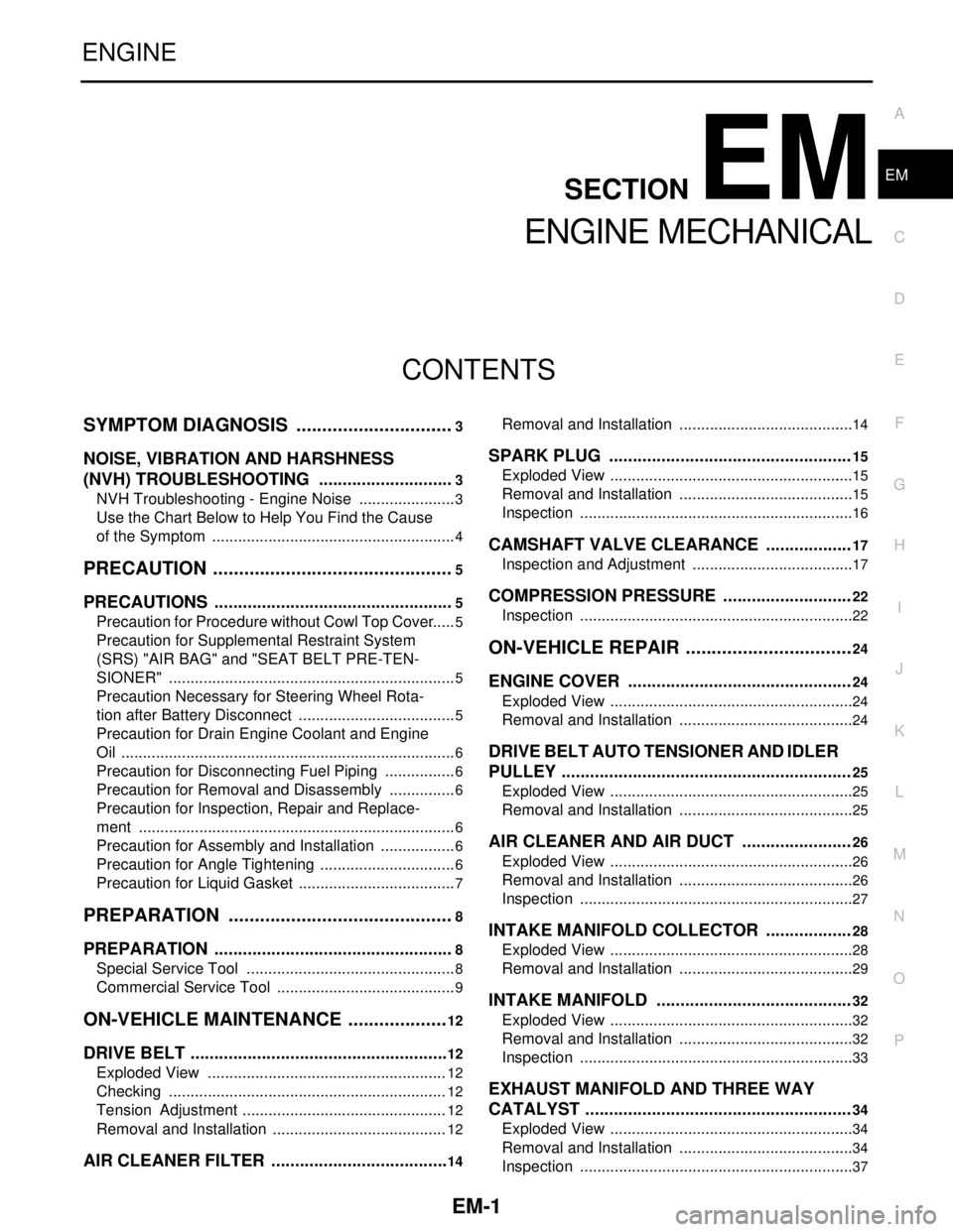
CONTENTS
ENGINE MECHANICAL
SYMPTOM DIAGNOSIS ...............................3
NOISE, VIBRATION AND HARSHNESS
(NVH) TROUBLESHOOTING .............................
3
NVH Troubleshooting - Engine Noise .......................3
Use the Chart Below to Help You Find the Cause
of the Symptom .........................................................
4
PRECAUTION ...............................................5
PRECAUTIONS ...................................................5
Precaution for Procedure without Cowl Top Cover ......5
Precaution for Supplemental Restraint System
(SRS) "AIR BAG" and "SEAT BELT PRE-TEN-
SIONER" ...................................................................
5
Precaution Necessary for Steering Wheel Rota-
tion after Battery Disconnect .....................................
5
Precaution for Drain Engine Coolant and Engine
Oil ..............................................................................
6
Precaution for Disconnecting Fuel Piping .................6
Precaution for Removal and Disassembly ................6
Precaution for Inspection, Repair and Replace-
ment ..........................................................................
6
Precaution for Assembly and Installation ..................6
Precaution for Angle Tightening ................................6
Precaution for Liquid Gasket .....................................7
PREPARATION ............................................8
PREPARATION ...................................................8
Special Service Tool .................................................8
Commercial Service Tool ..........................................9
ON-VEHICLE MAINTENANCE ....................12
DRIVE BELT .......................................................12
Exploded View ........................................................12
Checking .................................................................12
Tension Adjustment ................................................12
Removal and Installation .........................................12
AIR CLEANER FILTER ......................................14
Removal and Installation .........................................14
SPARK PLUG ...................................................15
Exploded View .........................................................15
Removal and Installation .........................................15
Inspection ................................................................16
CAMSHAFT VALVE CLEARANCE ..................17
Inspection and Adjustment ......................................17
COMPRESSION PRESSURE ...........................22
Inspection ................................................................22
ON-VEHICLE REPAIR .................................24
ENGINE COVER ...............................................24
Exploded View .........................................................24
Removal and Installation .........................................24
DRIVE BELT AUTO TENSIONER AND IDLER
PULLEY .............................................................
25
Exploded View .........................................................25
Removal and Installation .........................................25
AIR CLEANER AND AIR DUCT .......................26
Exploded View .........................................................26
Removal and Installation .........................................26
Inspection ................................................................27
INTAKE MANIFOLD COLLECTOR ..................28
Exploded View .........................................................28
Removal and Installation .........................................29
INTAKE MANIFOLD .........................................32
Exploded View .........................................................32
Removal and Installation .........................................32
Inspection ................................................................33
EXHAUST MANIFOLD AND THREE WAY
CATALYST ........................................................
34
Exploded View .........................................................34
Removal and Installation .........................................34
Inspection ................................................................37
Page 1877 of 5121

EM-2
OIL PAN AND OIL STRAINER ..........................38
Exploded View ........................................................38
Removal and Installation ........................................38
Inspection ...............................................................42
FUEL INJECTOR AND FUEL TUBE .................44
Exploded View ........................................................44
Removal and Installation ........................................44
Inspection ...............................................................48
IGNITION COIL, SPARK PLUG AND ROCK-
ER COVER .........................................................
49
Exploded View ........................................................49
Removal and Installation ........................................49
TIMING CHAIN ..................................................52
Exploded View ........................................................52
Removal and Installation ........................................53
Inspection ...............................................................65
REMOVAL AND INSTALLATION ...............67
ENGINE ASSEMBLY .........................................67
Exploded View ........................................................67
Removal and Installation ........................................67
Inspection ...............................................................75
DISASSEMBLY AND ASSEMBLY .............76
ENGINE STAND SETTING ................................76
Setting ....................................................................76
ENGINE UNIT ....................................................78
Disassembly ...........................................................78
Assembly ................................................................78
REAR TIMING CHAIN CASE ............................79
Exploded View ........................................................79
Disassembly and Assembly ....................................80
CAMSHAFT .......................................................84
Exploded View ........................................................84
Removal and Installation ........................................84
Inspection ...............................................................88
OIL SEAL ...........................................................93
VALVE OIL SEAL .....................................................93
VALVE OIL SEAL : Removal and Installation .........93
FRONT OIL SEAL .....................................................93
FRONT OIL SEAL : Removal and Installation ........93
REAR OIL SEAL .......................................................94
REAR OIL SEAL : Removal and Installation ...........94
CYLINDER HEAD ..............................................96
Exploded View ........................................................96
Removal and Installation .........................................97
Disassembly and Assembly ..................................100
Inspection ..............................................................104
CYLINDER BLOCK ..........................................107
Exploded View ......................................................107
Disassembly and Assembly ..................................110
Inspection ..............................................................119
HOW TO SELECT PISTON AND BEARING ...129
Description ............................................................129
Piston ....................................................................129
Connecting Rod Bearing .....................................130
Main Bearing ........................................................132
SERVICE DATA AND SPECIFICATIONS
(SDS) .........................................................
135
SERVICE DATA AND SPECIFICATIONS
(SDS) ................................................................
135
General Specification ...........................................135
Drive Belt ..............................................................136
Spark Plug ............................................................136
Intake Manifold ......................................................136
Exhaust Manifold ..................................................136
Camshaft ...............................................................136
Cylinder Head ......................................................139
Cylinder Block ......................................................143
Main Bearing ........................................................146
Connecting Rod Bearing .....................................147
Page 1879 of 5121

EM-4
< SYMPTOM DIAGNOSIS >
NOISE, VIBRATION AND HARSHNESS (NVH) TROUBLESHOOTING
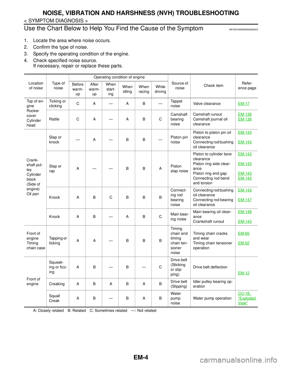
Use the Chart Below to Help You Find the Cause of the Symptom
INFOID:0000000003802223
1. Locate the area where noise occurs.
2. Confirm the type of noise.
3. Specify the operating condition of the engine.
4. Check specified noise source.
If necessary, repair or replace these parts.
A: Closely related B: Related C: Sometimes related —: Not related Location
of noiseType of
noiseOperating condition of engine
Source of
noiseCheck itemRefer-
ence page Before
warm-
upAfter
warm-
upWhen
start-
ingWhen
idlingWhen
racingWhile
driving
Top of en-
gine
Rocker
cover
Cylinder
headTicking or
clickingCA—AB—Tappet
noiseValve clearanceEM-17
Rattle C A — A B CCamshaft
bearing
noiseCamshaft runout
Camshaft journal oil
clearanceEM-136EM-136
Crank-
shaft pul-
ley
Cylinder
block
(Side of
engine)
Oil panSlap or
knock—A—B B—Piston pin
noisePiston to piston pin oil
clearance
Connecting rod bushing
oil clearanceEM-143
EM-143
Slap or
rapA——B B APiston
slap noisePiston to cylinder bore
clearance
Piston ring side clear-
ance
Piston ring end gap
Connecting rod bend
and torsionEM-143EM-143
EM-143
EM-143
Knock A B C B B BConnect-
ing rod
bearing
noiseConnecting rod bushing
oil clearance
Connecting rod bearing
oil clearanceEM-143EM-147
Knock A B — A B CMain bear-
ing noiseMain bearing oil clear-
ance
Crankshaft runoutEM-146
EM-143
Front of
engine
Timing
chain caseTapping or
tickingAA—BBBTiming
chain and
timing
chain ten-
sioner
noiseTiming chain cracks
and wear
Timing chain tensioner
operationEM-65
EM-52
Front of
engineSqueak-
ing or fizz-
ingAB—B—CDrive belt
(Sticking
or slip-
ping)Drive belt deflection
EM-12
CreakingABABABDrive belt
(Slipping)Idler pulley bearing op-
eration
Squall
CreakAB—BABWater
pump
noiseWater pump operationCO-18,
"Exploded
View"
Page 1881 of 5121

EM-6
< PRECAUTION >
PRECAUTIONS
3. Disconnect both battery cables. The steering lock will remain released with both battery cables discon-
nected and the steering wheel can be turned.
4. Perform the necessary repair operation.
5. When the repair work is completed, re-connect both battery cables. With the brake pedal released, turn
the push-button ignition switch from ACC position to ON position, then to LOCK position. (The steering
wheel will lock when the push-button ignition switch is turned to LOCK position.)
6. Perform self-diagnosis check of all control units using CONSULT-III.
Precaution for Drain Engine Coolant and Engine OilINFOID:0000000003802227
Drain engine coolant and engine oil when the engine is cooled.
Precaution for Disconnecting Fuel PipingINFOID:0000000003802228
Before starting work, check no fire or spark producing items are in the work area.
Release fuel pressure before disconnecting and disassembly.
After disconnecting pipes, plug openings to stop fuel leakage.
Precaution for Removal and DisassemblyINFOID:0000000003802229
When instructed to use SST, use the specified tools. Always be careful to work safely, avoid forceful or unin-
structed operations.
Exercise maximum care to avoid damage to mating or sliding surfaces.
Dowel pins are used for several parts alignment. When replacing and reassembling parts with dowel pins,
check that dowel pins are installed in the original position.
Cover openings of engine system with a tape or the equivalent, if necessary, to seal out foreign materials.
Mark and arrange disassembly parts in an organized way for easy troubleshooting and reassembly.
When loosening nuts and bolts, as a basic rule, start with the one furthest outside, then the one diagonally
opposite, and so on. If the order of loosening is specified, do exactly as specified. Power tools may be used
in the step.
Precaution for Inspection, Repair and ReplacementINFOID:0000000003802230
Before repairing or replacing, thoroughly inspect parts. Inspect new replacement parts in the same way, and
replace if necessary.
Precaution for Assembly and InstallationINFOID:0000000003802231
Use torque wrench to tighten bolts or nuts to specification.
When tightening nuts and bolts, as a basic rule, equally tighten in several different steps starting with the
ones in center, then ones on inside and outside diagonally in this order. If the order of tightening is specified,
do exactly as specified.
Replace with new gasket, packing, oil seal or O-ring.
Dowel pins are used for several parts alignment. When replacing and reassembling parts with dowel pins,
check that dowel pins are installed in the original position.
Thoroughly wash, clean, and air-blow each part. Carefully check engine oil or engine coolant passages for
any restriction and blockage.
Avoid damaging sliding or mating surfaces. Completely remove foreign materials such as cloth lint or dust.
Before assembly, oil sliding surfaces well.
Release air within route when refilling after draining engine coolant.
After repairing, start the engine and increase engine speed to check engine coolant, fuel, engine oil, and
exhaust gases for leakage.
Precaution for Angle TighteningINFOID:0000000003802232
Use the angle wrench [SST: KV10112100 (BT8653-A)] for the final tightening of the following engine parts:
- Cylinder head bolts
- Main bearing cap bolts
- Connecting rod cap bolts
- Crankshaft pulley bolt (No the angle wrench is required as bolt flange is provided with notches for angle
tightening)
Never use a torque value for final tightening.
The torque value for these parts are for a preliminary step.
Page 1882 of 5121

PRECAUTIONS
EM-7
< PRECAUTION >
C
D
E
F
G
H
I
J
K
L
MA
EM
N
P O
Ensure thread and seat surfaces are clean and coated with engine oil.
Precaution for Liquid GasketINFOID:0000000003802233
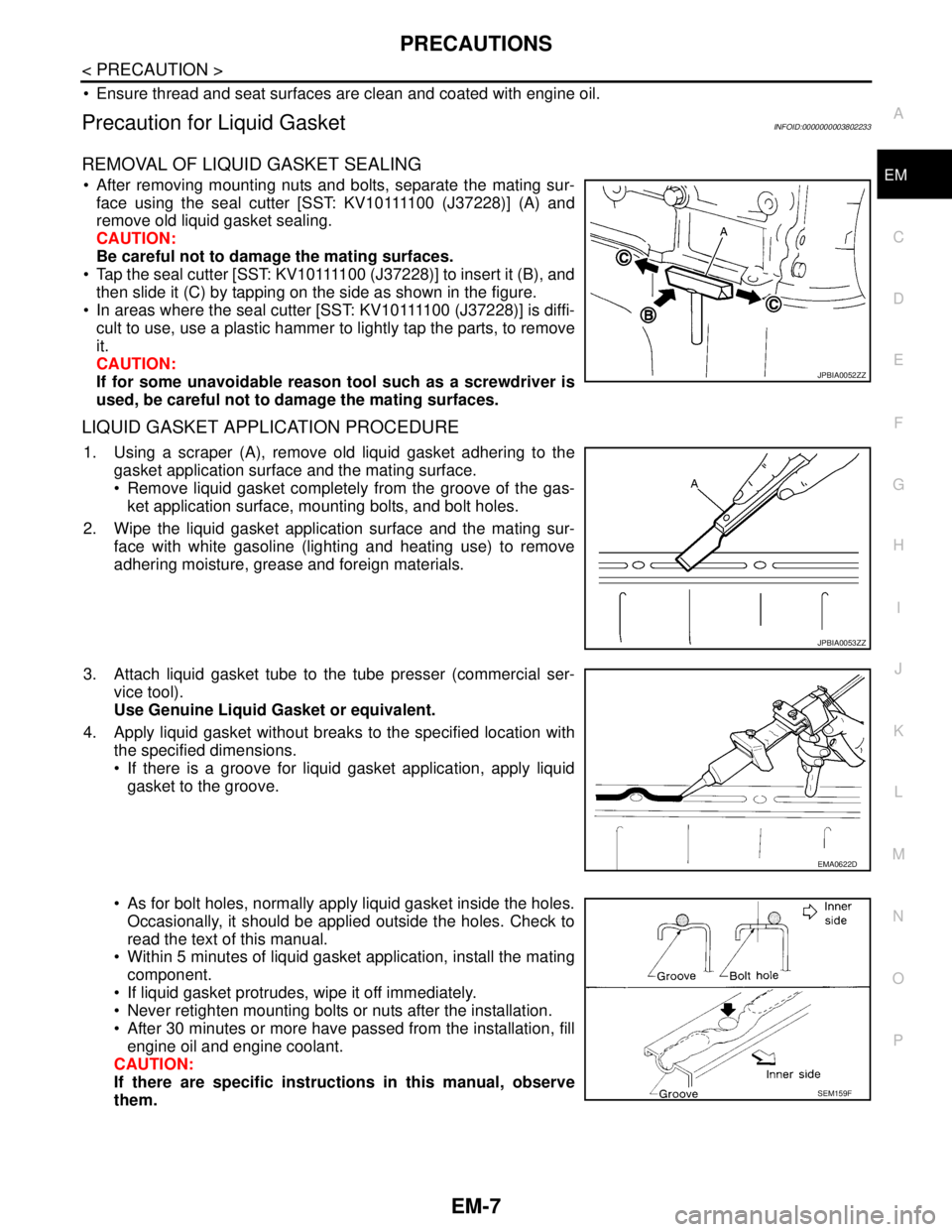
REMOVAL OF LIQUID GASKET SEALING
After removing mounting nuts and bolts, separate the mating sur-
f a c e u s i n g t h e s e a l c u t t e r [ S S T: K V 1 0 1111 0 0 ( J37228)] (A) and
remove old liquid gasket sealing.
CAUTION:
Be careful not to damage the mating surfaces.
Tap the seal cutter [SST: KV10111100 (J37228)] to insert it (B), and
then slide it (C) by tapping on the side as shown in the figure.
In areas where the seal cutter [SST: KV10111100 (J37228)] is diffi-
cult to use, use a plastic hammer to lightly tap the parts, to remove
it.
CAUTION:
If for some unavoidable reason tool such as a screwdriver is
used, be careful not to damage the mating surfaces.
LIQUID GASKET APPLICATION PROCEDURE
1. Using a scraper (A), remove old liquid gasket adhering to the
gasket application surface and the mating surface.
Remove liquid gasket completely from the groove of the gas-
ket application surface, mounting bolts, and bolt holes.
2. Wipe the liquid gasket application surface and the mating sur-
face with white gasoline (lighting and heating use) to remove
adhering moisture, grease and foreign materials.
3. Attach liquid gasket tube to the tube presser (commercial ser-
vice tool).
Use Genuine Liquid Gasket or equivalent.
4. Apply liquid gasket without breaks to the specified location with
the specified dimensions.
If there is a groove for liquid gasket application, apply liquid
gasket to the groove.
As for bolt holes, normally apply liquid gasket inside the holes.
Occasionally, it should be applied outside the holes. Check to
read the text of this manual.
Within 5 minutes of liquid gasket application, install the mating
component.
If liquid gasket protrudes, wipe it off immediately.
Never retighten mounting bolts or nuts after the installation.
After 30 minutes or more have passed from the installation, fill
engine oil and engine coolant.
CAUTION:
If there are specific instructions in this manual, observe
them.
JPBIA0052ZZ
JPBIA0053ZZ
EMA0622D
SEM159F