2008 NISSAN LATIO battery
[x] Cancel search: batteryPage 433 of 2771
BCM (BODY CONTROL MODULE)
BCS-17
< SERVICE INFORMATION >
C
D
E
F
G
H
I
J
L
MA
B
BCS
N
O
P
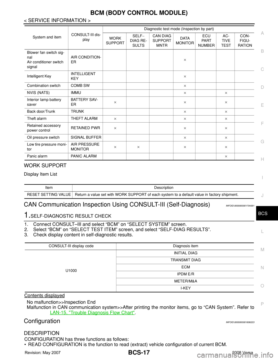
WORK SUPPORT
Display Item List
CAN Communication Inspection Using CONSULT-III (Self-Diagnosis)INFOID:0000000001704591
1.SELF-DIAGNOSTIC RESULT CHECK
1. Connect CONSULT–III and select “BCM” on “SELECT SYSTEM” screen.
2. Select “BCM” on “SELECT TEST ITEM” screen, and select “SELF-DIAG RESULTS”.
3. Check display content in self-diagnostic results.
Contents displayed
No malfunction>>Inspection End
Malfunction in CAN communication system>>After printing the monitor items, go to “CAN System”. Refer to
LAN-15, "
Trouble Diagnosis Flow Chart".
ConfigurationINFOID:0000000001806223
DESCRIPTION
CONFIGURATION has three functions as follows:
• READ CONFIGURATION is the function to read (extract) vehicle configuration of current BCM.
Blower fan switch sig-
nal
Air conditioner switch
signalAIR CONDITION-
ER×
Intelligent KeyINTELLIGENT
KEY×
Combination switch COMB SW×
NVIS (NATS) IMMU××
Interior lamp battery
saverBATTERY SAV-
ER×××
Back door/Trunk TRUNK××
Theft alarm THEFT ALARM×××
Retained accessory
power controlRETAINED PWR×××
Oil pressure switch SIGNAL BUFFER××
Low tire pressure moni-
torAIR PRESSURE
MONITOR×× × ×
Panic alarm PANIC ALARM× System and itemCONSULT-III dis-
playDiagnostic test mode (Inspection by part)
WORK
SUPPORTSELF−
DIAG RE-
SULTSCAN DIAG
SUPPORT
MNTRDATA
MONITORECU
PA R T
NUMBERAC-
TIVE
TESTCON-
FIGU-
RATION
Item Description
RESET SETTING VALUE Return a value set with WORK SUPPORT of each system to a default value in factory shipment.
CONSULT-III display code Diagnosis item
U1000INITIAL DIAG
TRANSMIT DIAG
ECM
IPDM E/R
METER/M&A
I-KEY
Page 435 of 2771

BL-1
BODY
C
D
E
F
G
H
J
K
L
M
SECTION BL
A
B
BL
N
O
P
CONTENTS
BODY, LOCK & SECURITY SYSTEM
SERVICE INFORMATION ............................4
PRECAUTIONS ...................................................4
Precaution for Supplemental Restraint System
(SRS) "AIR BAG" and "SEAT BELT PRE-TEN-
SIONER" ...................................................................
4
Precaution Necessary for Steering Wheel Rota-
tion After Battery Disconnect .....................................
4
Precaution for Procedure without Cowl Top Cover ......5
Precaution for Work ..................................................5
PREPARATION ...................................................6
Special Service Tool .................................................6
Commercial Service Tool ..........................................6
SQUEAK AND RATTLE TROUBLE DIAG-
NOSES ................................................................
7
Work Flow .................................................................7
Generic Squeak and Rattle Troubleshooting ............9
Diagnostic Worksheet .............................................11
HOOD .................................................................13
Fitting Adjustment ...................................................13
Removal and Installation .........................................14
Removal and Installation of Hood Lock Control ......15
Hood Lock Control Inspection .................................17
RADIATOR CORE SUPPORT ...........................19
Removal and Installation .........................................19
FRONT FENDER ................................................21
Removal and Installation .........................................21
POWER DOOR LOCK SYSTEM ........................22
Component Parts and Harness Connector Loca-
tion ..........................................................................
22
System Description .................................................22
CAN Communication System Description ...............24
Schematic ...............................................................25
Wiring Diagram - D/LOCK - .....................................26
Schematic ...............................................................30
Wiring Diagram - D/LOCK - .....................................31
Terminal and Reference Value for BCM ..................35
Work Flow ................................................................35
CONSULT-III Function (BCM) .................................36
Trouble Diagnosis Symptom Chart ..........................37
BCM Power Supply and Ground Circuit ..................37
Door Switch Check (Hatchback) ..............................37
Door Switch Check (Sedan) ....................................40
Key Switch (Insert) Check .......................................41
Door Lock and Unlock Switch Check ......................42
Front Door Lock Assembly LH (Actuator) Check .....45
Door Lock Actuator Check (Front RH and Rear
LH/RH) .....................................................................
46
Front Door Key Cylinder Switch LH Check ..............47
Passenger Select Unlock Relay Circuit Inspection
(With Intelligent Key) ...............................................
48
REMOTE KEYLESS ENTRY SYSTEM .............51
Component Parts and Harness Connector Loca-
tion ...........................................................................
51
System Description ..................................................51
CAN Communication System Description ...............53
Schematic ................................................................54
Wiring Diagram - KEYLES - ....................................55
Terminal and Reference Value for BCM ..................57
How to Perform Trouble Diagnosis ..........................57
Preliminary Check ...................................................58
CONSULT-III Function (BCM) .................................58
Work Flow ................................................................59
Trouble Diagnosis Symptom Chart ..........................60
Keyfob Battery and Function Check ........................61
ACC Switch Check ..................................................62
Door Switch Check (Hatchback) ..............................62
Door Switch Check (Sedan) ....................................65
Key Switch (Insert) Check .......................................66
Hazard Function Check ...........................................67
Horn Function Check ...............................................67
Interior Lamp and Ignition Keyhole Illumination
Function Check ........................................................
68
Remote Keyless Entry Receiver Check ...................68
Keyfob Function (Lock) Check ................................71
Keyfob Function (Unlock) Check .............................71
Page 436 of 2771

BL-2
ID Code Entry Procedure .......................................71
Keyfob Battery Replacement ..................................73
Removal and Installation of Remote Keyless Entry
Receiver .................................................................
73
INTELLIGENT KEY SYSTEM ............................74
Component Parts and Harness Connector Loca-
tion ..........................................................................
74
System Description .................................................76
CAN Communication System Description ..............83
Schematic ...............................................................84
Wiring Diagram - I/KEY - ........................................86
Intelligent Key Unit Harness Connector Terminal
Layout .....................................................................
96
Terminal and Reference Value for Intelligent Key
Unit .........................................................................
96
Steering Lock Solenoid Harness Connector Ter-
minal Layout ...........................................................
98
Terminal and Reference Value for Steering Lock
Solenoid ..................................................................
98
Terminal and Reference Value for BCM .................99
Trouble Diagnosis Procedure .................................99
CONSULT-III Functions (INTELLIGENT KEY) ......100
CONSULT-III Application Item ...............................101
Trouble Diagnosis Symptom Chart ........................103
CAN Communication System Inspection ...............109
Power Supply and Ground Circuit Inspection ........110
Key Switch (Intelligent Key Unit Input) Check .......110
Key Switch (BCM Input) Check .............................112
Ignition Knob Switch Check ...................................113
Door Switch Check (Hatchback) ............................114
Door Switch Check (Sedan) ..................................117
Door Request Switch Check ..................................118
Back Door Request Switch Check (Hatchback) ....120
Trunk Opener Request Switch Check (Sedan) .....122
Unlock Sensor Check ............................................124
Intelligent Key Warning Buzzer(s) Check ..............125
Outside Key Antenna (Driver Side and Passenger
Side) Check ...........................................................
126
Outside Key Antenna (Rear Bumper) Check .........128
Inside Key Antenna Check ....................................129
Steering Lock Solenoid Check ..............................131
Key Interlock Solenoid (With M/T) Check ..............133
Ignition Switch Position Check ..............................134
Stop Lamp Switch Check (With CVT) ....................134
Stop Lamp Switch Check (With M/T) .....................135
Check CVT Device (Park Position Switch) Check ..136
"P-SHIFT" Warning Lamp (With CVT) Check ........138
"LOCK" Warning Lamp (With M/T) Check .............138
"KEY" Warning Lamp (RED) Check ......................139
"KEY" Warning Lamp (GREEN) Check .................139
Check Warning Chime in Combination Meter ........140
Hazard Function Check .........................................140
Horn Function Check .............................................140
Headlamp Function Check ....................................141
Intelligent Key Battery Replacement .....................142
Remote Keyless Entry Function ............................142
Removal and Installation of Intelligent Key Unit ....142
DOOR ...............................................................144
Fitting Adjustment .................................................144
Removal and Installation .......................................147
FRONT DOOR LOCK .......................................150
Component Parts Location ...................................150
Removal and Installation .......................................150
REAR DOOR LOCK .........................................153
Component Parts Location ...................................153
Removal and Installation .......................................153
BACK DOOR LOCK .........................................156
Component Parts and Harness Connector Loca-
tion ........................................................................
156
System Description ...............................................156
Wiring Diagram - B/DOOR - ..................................157
Terminal and Reference Value for BCM ...............158
Terminal and Reference Value for Intelligent Key
Unit ........................................................................
158
CONSULT-III Function (BCM) ..............................159
Work Flow .............................................................159
Trouble Diagnosis Chart by Symptom ..................159
BCM Power Supply and Ground Circuit ................160
Check Back Door Opener Switch Circuit (Without
Intelligent Key or Power Windows) .......................
160
Check Back Door Opener Switch Circuit (Without
Intelligent Key, with Power Windows) ...................
162
Check Back Door Opener Switch Circuit (With In-
telligent Key) .........................................................
165
Check Back Door Lock Assembly (Actuator) Cir-
cuit ........................................................................
166
Removal and Installation .......................................168
TRUNK LID .......................................................170
Fitting Adjustment .................................................170
Trunk Lid Assembly ..............................................170
Trunk Lid Lock ......................................................171
Trunk Lid Striker ....................................................171
TRUNK LID OPENER .......................................173
Component Parts and Harness Connector Loca-
tion ........................................................................
173
System Description ...............................................173
Wiring Diagram - TLID - ........................................174
Terminal and Reference Value for BCM ...............175
Terminal and Reference Value for Intelligent Key
Unit ........................................................................
175
CONSULT-III Function (BCM) ..............................176
Work Flow .............................................................176
Trouble Diagnosis Chart by Symptom ..................176
BCM Power Supply and Ground Circuit ................177
Check Trunk Lid Opener Switch Circuit (Without
Intelligent Key or Power Windows) .......................
177
Check Trunk Lid Opener Switch Circuit (Without
Intelligent Key, with Power Windows) ...................
179
Check Trunk Lid Opener Switch Circuit (With Intel-
ligent Key) .............................................................
182
Check Trunk Release Solenoid Circuit .................183
Page 438 of 2771
BL-4
< SERVICE INFORMATION >
PRECAUTIONS
SERVICE INFORMATION
PRECAUTIONS
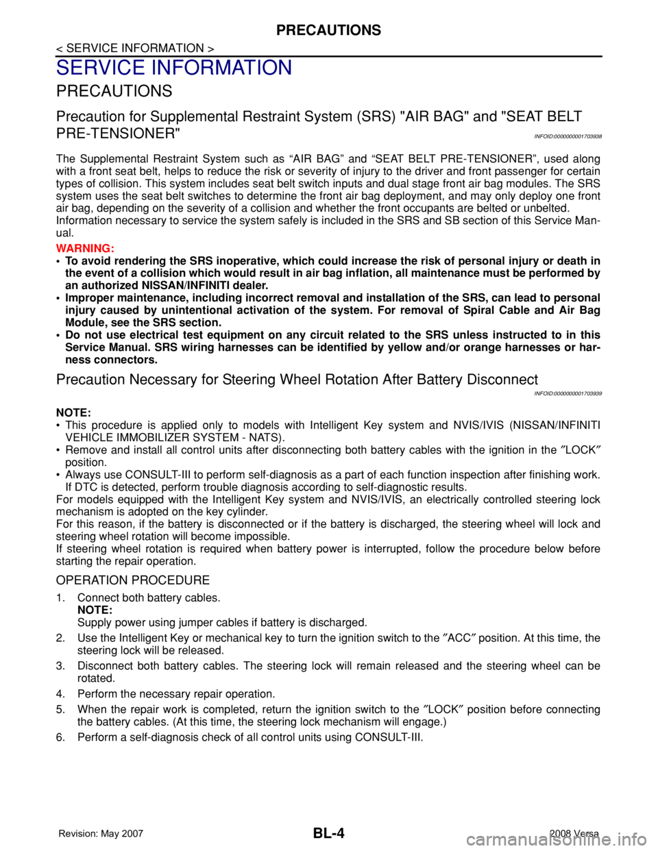
Precaution for Supplemental Restraint System (SRS) "AIR BAG" and "SEAT BELT
PRE-TENSIONER"
INFOID:0000000001703938
The Supplemental Restraint System such as “AIR BAG” and “SEAT BELT PRE-TENSIONER”, used along
with a front seat belt, helps to reduce the risk or severity of injury to the driver and front passenger for certain
types of collision. This system includes seat belt switch inputs and dual stage front air bag modules. The SRS
system uses the seat belt switches to determine the front air bag deployment, and may only deploy one front
air bag, depending on the severity of a collision and whether the front occupants are belted or unbelted.
Information necessary to service the system safely is included in the SRS and SB section of this Service Man-
ual.
WARNING:
• To avoid rendering the SRS inoperative, which could increase the risk of personal injury or death in
the event of a collision which would result in air bag inflation, all maintenance must be performed by
an authorized NISSAN/INFINITI dealer.
• Improper maintenance, including incorrect removal and installation of the SRS, can lead to personal
injury caused by unintentional activation of the system. For removal of Spiral Cable and Air Bag
Module, see the SRS section.
• Do not use electrical test equipment on any circuit related to the SRS unless instructed to in this
Service Manual. SRS wiring harnesses can be identified by yellow and/or orange harnesses or har-
ness connectors.
Precaution Necessary for Steering Wheel Rotation After Battery Disconnect
INFOID:0000000001703939
NOTE:
• This procedure is applied only to models with Intelligent Key system and NVIS/IVIS (NISSAN/INFINITI
VEHICLE IMMOBILIZER SYSTEM - NATS).
• Remove and install all control units after disconnecting both battery cables with the ignition in the ″LOCK″
position.
• Always use CONSULT-III to perform self-diagnosis as a part of each function inspection after finishing work.
If DTC is detected, perform trouble diagnosis according to self-diagnostic results.
For models equipped with the Intelligent Key system and NVIS/IVIS, an electrically controlled steering lock
mechanism is adopted on the key cylinder.
For this reason, if the battery is disconnected or if the battery is discharged, the steering wheel will lock and
steering wheel rotation will become impossible.
If steering wheel rotation is required when battery power is interrupted, follow the procedure below before
starting the repair operation.
OPERATION PROCEDURE
1. Connect both battery cables.
NOTE:
Supply power using jumper cables if battery is discharged.
2. Use the Intelligent Key or mechanical key to turn the ignition switch to the ″ACC″ position. At this time, the
steering lock will be released.
3. Disconnect both battery cables. The steering lock will remain released and the steering wheel can be
rotated.
4. Perform the necessary repair operation.
5. When the repair work is completed, return the ignition switch to the ″LOCK″ position before connecting
the battery cables. (At this time, the steering lock mechanism will engage.)
6. Perform a self-diagnosis check of all control units using CONSULT-III.
Page 472 of 2771
BL-38
< SERVICE INFORMATION >
POWER DOOR LOCK SYSTEM
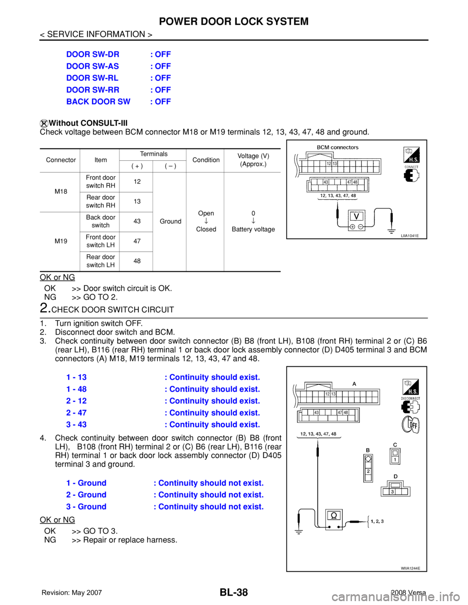
Without CONSULT-III
Check voltage between BCM connector M18 or M19 terminals 12, 13, 43, 47, 48 and ground.
OK or NG
OK >> Door switch circuit is OK.
NG >> GO TO 2.
2.CHECK DOOR SWITCH CIRCUIT
1. Turn ignition switch OFF.
2. Disconnect door switch and BCM.
3. Check continuity between door switch connector (B) B8 (front LH), B108 (front RH) terminal 2 or (C) B6
(rear LH), B116 (rear RH) terminal 1 or back door lock assembly connector (D) D405 terminal 3 and BCM
connectors (A) M18, M19 terminals 12, 13, 43, 47 and 48.
4. Check continuity between door switch connector (B) B8 (front
LH), B108 (front RH) terminal 2 or (C) B6 (rear LH), B116 (rear
RH) terminal 1 or back door lock assembly connector (D) D405
terminal 3 and ground.
OK or NG
OK >> GO TO 3.
NG >> Repair or replace harness.DOOR SW-DR : OFF
DOOR SW-AS : OFF
DOOR SW-RL : OFF
DOOR SW-RR : OFF
BACK DOOR SW : OFF
Connector ItemTe r m i n a l s
ConditionVoltage (V)
(Approx.)
( + ) ( – )
M18Front door
switch RH12
GroundOpen
↓
Closed0
↓
Battery voltage Rear door
switch RH13
M19Back door
switch43
Front door
switch LH47
Rear door
switch LH48
LIIA1041E
1 - 13 : Continuity should exist.
1 - 48 : Continuity should exist.
2 - 12 : Continuity should exist.
2 - 47 : Continuity should exist.
3 - 43 : Continuity should exist.
1 - Ground : Continuity should not exist.
2 - Ground : Continuity should not exist.
3 - Ground : Continuity should not exist.
WIIA1244E
Page 474 of 2771
BL-40
< SERVICE INFORMATION >
POWER DOOR LOCK SYSTEM
NG >> Repair or replace harness.
Door Switch Check (Sedan)INFOID:0000000001703966
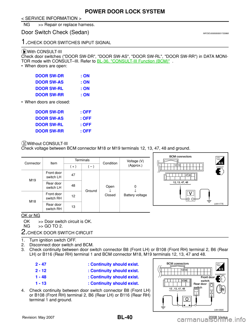
1.CHECK DOOR SWITCHES INPUT SIGNAL
With CONSULT-III
Check door switches ("DOOR SW-DR", "DOOR SW-AS", "DOOR SW-RL", "DOOR SW-RR") in DATA MONI-
TOR mode with CONSULT–III. Refer to BL-36, "
CONSULT-III Function (BCM)" .
• When doors are open:
• When doors are closed:
Without CONSULT-III
Check voltage between BCM connector M18 or M19 terminals 12, 13, 47, 48 and ground.
OK or NG
OK >> Door switch circuit is OK.
NG >> GO TO 2.
2.CHECK DOOR SWITCH CIRCUIT
1. Turn ignition switch OFF.
2. Disconnect door switch and BCM.
3. Check continuity between door switch connector B8 (Front LH) or B108 (Front RH) terminal 2, B6 (Rear
LH) or B116 (Rear RH) terminal 1 and BCM connector M18, M19 terminals 12, 13, 47 and 48.
4. Check continuity between door switch connector B8 (Front LH)
or B108 (Front RH) terminal 2, B6 (Rear LH) or B116 (Rear RH)
terminal 1 and ground.DOOR SW-DR : ON
DOOR SW-AS : ON
DOOR SW-RL : ON
DOOR SW-RR : ON
DOOR SW-DR : OFF
DOOR SW-AS : OFF
DOOR SW-RL : OFF
DOOR SW-RR : OFF
Connector ItemTe r m i n a l s
ConditionVoltage (V)
(Approx.)
( + ) ( – )
M19Front door
switch LH47
GroundOpen
↓
Closed0
↓
Battery voltage Rear door
switch LH48
M18Front door
switch RH12
Rear door
switch RH13
LIIA1177E
2 - 47 : Continuity should exist.
2 - 12 : Continuity should exist.
1 - 48 : Continuity should exist.
1 - 13 : Continuity should exist.
LIIA1350E
Page 475 of 2771
POWER DOOR LOCK SYSTEM
BL-41
< SERVICE INFORMATION >
C
D
E
F
G
H
J
K
L
MA
B
BL
N
O
P
OK or NG
OK >> GO TO 3.
NG >> Repair or replace harness.
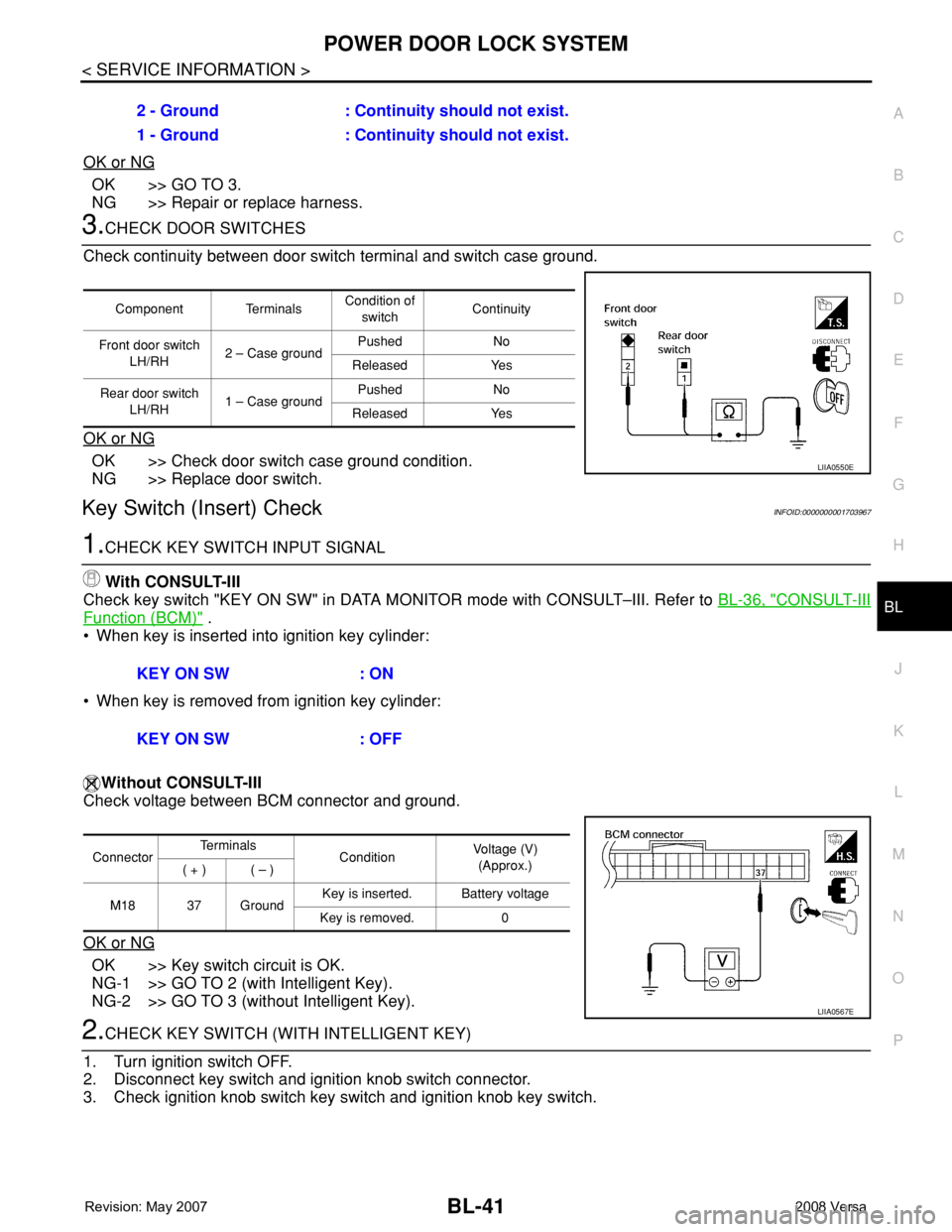
3.CHECK DOOR SWITCHES
Check continuity between door switch terminal and switch case ground.
OK or NG
OK >> Check door switch case ground condition.
NG >> Replace door switch.
Key Switch (Insert) CheckINFOID:0000000001703967
1.CHECK KEY SWITCH INPUT SIGNAL
With CONSULT-III
Check key switch "KEY ON SW" in DATA MONITOR mode with CONSULT–III. Refer to BL-36, "
CONSULT-III
Function (BCM)" .
• When key is inserted into ignition key cylinder:
• When key is removed from ignition key cylinder:
Without CONSULT-III
Check voltage between BCM connector and ground.
OK or NG
OK >> Key switch circuit is OK.
NG-1 >> GO TO 2 (with Intelligent Key).
NG-2 >> GO TO 3 (without Intelligent Key).
2.CHECK KEY SWITCH (WITH INTELLIGENT KEY)
1. Turn ignition switch OFF.
2. Disconnect key switch and ignition knob switch connector.
3. Check ignition knob switch key switch and ignition knob key switch.2 - Ground : Continuity should not exist.
1 - Ground : Continuity should not exist.
Component TerminalsCondition of
switchContinuity
Front door switch
LH/RH2 – Case groundPushed No
Released Yes
Rear door switch
LH/RH1 – Case groundPushed No
Released Yes
LIIA0550E
KEY ON SW : ON
KEY ON SW : OFF
ConnectorTe r m i n a l s
ConditionVoltage (V)
(Approx.)
( + ) ( – )
M18 37 GroundKey is inserted. Battery voltage
Key is removed. 0
LIIA0567E
Page 477 of 2771
POWER DOOR LOCK SYSTEM
BL-43
< SERVICE INFORMATION >
C
D
E
F
G
H
J
K
L
MA
B
BL
N
O
P
OK or NG
OK >> Door lock and unlock switch is OK.
NG >> GO TO 2.
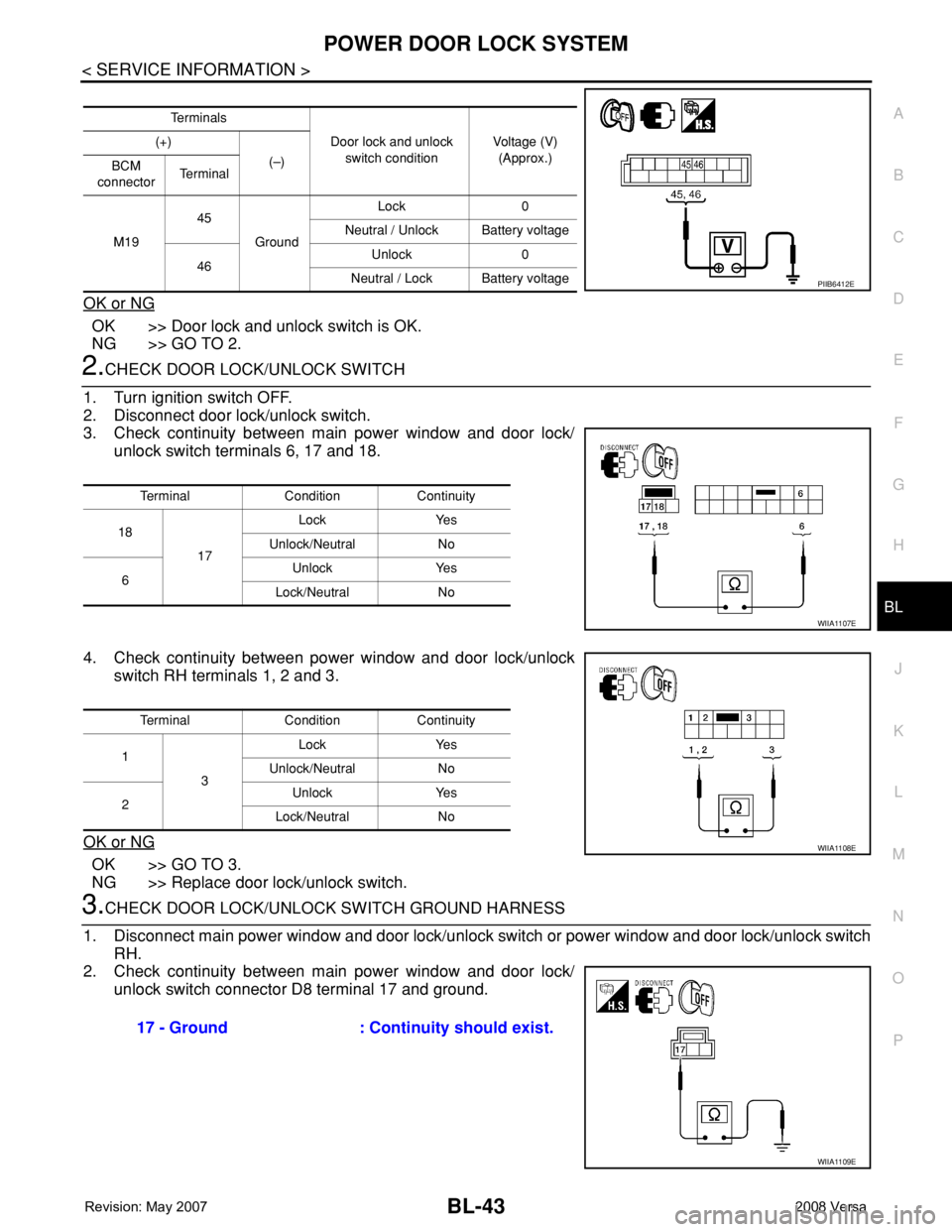
2.CHECK DOOR LOCK/UNLOCK SWITCH
1. Turn ignition switch OFF.
2. Disconnect door lock/unlock switch.
3. Check continuity between main power window and door lock/
unlock switch terminals 6, 17 and 18.
4. Check continuity between power window and door lock/unlock
switch RH terminals 1, 2 and 3.
OK or NG
OK >> GO TO 3.
NG >> Replace door lock/unlock switch.
3.CHECK DOOR LOCK/UNLOCK SWITCH GROUND HARNESS
1. Disconnect main power window and door lock/unlock switch or power window and door lock/unlock switch
RH.
2. Check continuity between main power window and door lock/
unlock switch connector D8 terminal 17 and ground.
Te r m i n a l s
Door lock and unlock
switch conditionVoltage (V)
(Approx.) (+)
(–)
BCM
connectorTe r m i n a l
M1945
GroundLock 0
Neutral / Unlock Battery voltage
46Unlock 0
Neutral / Lock Battery voltage
PIIB6412E
Terminal Condition Continuity
18
17Lock Yes
Unlock/Neutral No
6Unlock Yes
Lock/Neutral No
WIIA1107E
Terminal Condition Continuity
1
3Lock Yes
Unlock/Neutral No
2Unlock Yes
Lock/Neutral No
WIIA1108E
17 - Ground : Continuity should exist.
WIIA1109E