Page 2749 of 2771

WW-16
< SERVICE INFORMATION >
FRONT WIPER AND WASHER SYSTEM
1. Connect IPDM E/R.
2. Turn ignition ON.
3. Start auto active test. Refer to PG-19, "
Auto Active Test" .
4. Check voltage between IPDM E/R connector and ground while front wiper LO is operating.
OK or NG
OK >> Replace front wiper motor. Refer to WW-19, "Removal and Installation of Front Wiper Drive
Assembly" .
NG >> Replace IPDM E/R. Refer to PG-26, "
Removal and Installation of IPDM E/R" .
Only Front Wiper High Does Not OperateINFOID:0000000001704549
1.ACTIVE TEST
With CONSULT-Ill
1. Select “IPDM E/R” on CONSULT-III, and select “ACTIVE TEST” on “SELECT DIAG MODE” screen.
2. Select “FRONT WIPER” on “SELECT TEST ITEM” screen.
3. Touch “HI” screen.
Without CONSULT-lIl
Start auto active test. Refer to PG-19, "
Auto Active Test" .
Does front wiper operate normally?
YES >> Refer to LT-63, "Combination Switch Inspection" .
NO >> GO TO 2.
2.CHECK FRONT WIPER MOTOR CIRCUIT
1. Turn ignition switch OFF.
2. Disconnect IPDM E/R connector E45 and front wiper motor connector E1.
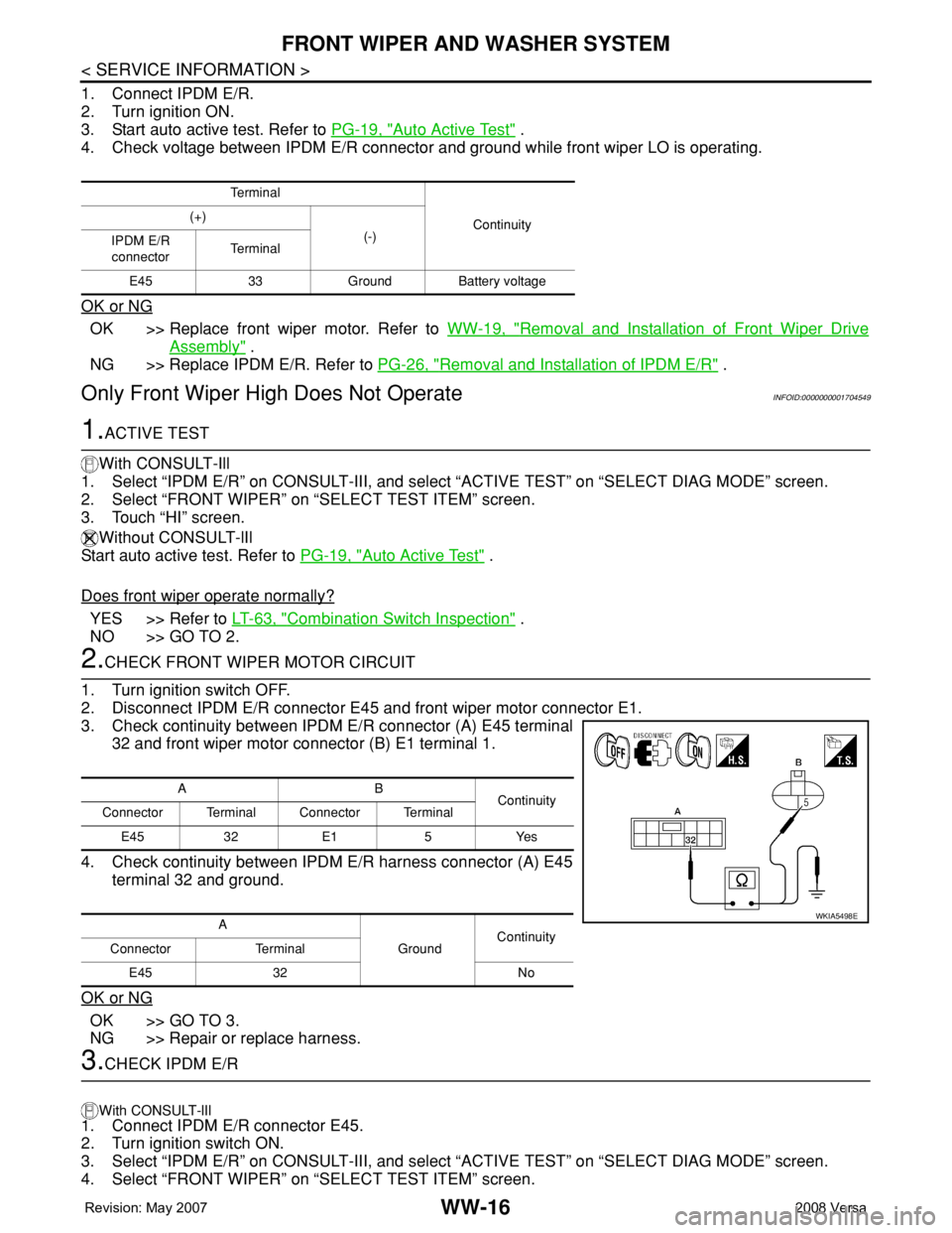
3. Check continuity between IPDM E/R connector (A) E45 terminal
32 and front wiper motor connector (B) E1 terminal 1.
4. Check continuity between IPDM E/R harness connector (A) E45
terminal 32 and ground.
OK or NG
OK >> GO TO 3.
NG >> Repair or replace harness.
3.CHECK IPDM E/R
With CONSULT-lIl
1. Connect IPDM E/R connector E45.
2. Turn ignition switch ON.
3. Select “IPDM E/R” on CONSULT-III, and select “ACTIVE TEST” on “SELECT DIAG MODE” screen.
4. Select “FRONT WIPER” on “SELECT TEST ITEM” screen.
Te r m i n a l
Continuity (+)
(-)
IPDM E/R
connectorTe r m i n a l
E45 33 Ground Battery voltage
AB
Continuity
Connector Terminal Connector Terminal
E45 32 E1 5 Yes
A
GroundContinuity
Connector Terminal
E45 32 No
WKIA5498E
Page 2750 of 2771

FRONT WIPER AND WASHER SYSTEM
WW-17
< SERVICE INFORMATION >
C
D
E
F
G
H
I
J
L
MA
B
WW
N
O
P
5. Touch “HI” screen.
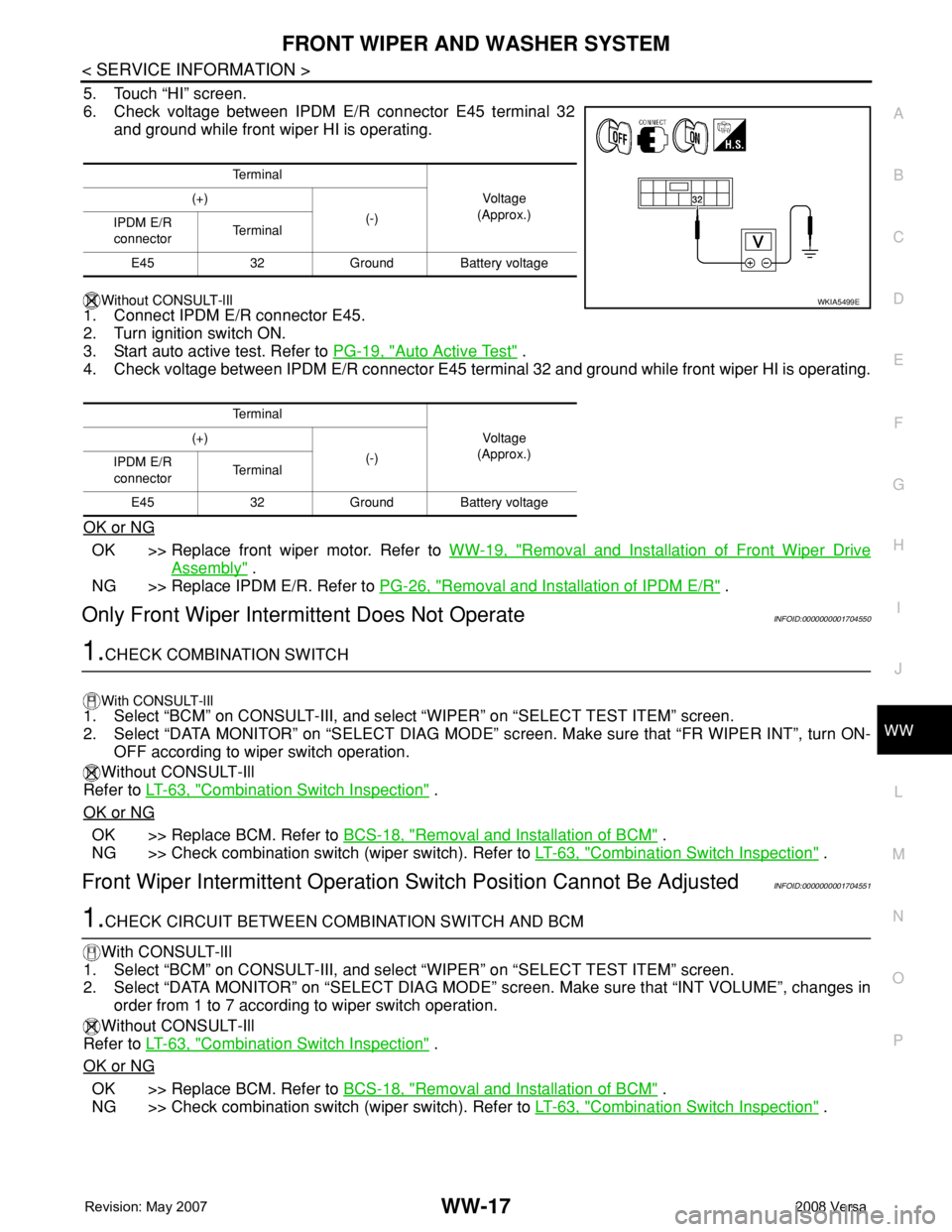
6. Check voltage between IPDM E/R connector E45 terminal 32
and ground while front wiper HI is operating.
Without CONSULT-lIl
1. Connect IPDM E/R connector E45.
2. Turn ignition switch ON.
3. Start auto active test. Refer to PG-19, "
Auto Active Test" .
4. Check voltage between IPDM E/R connector E45 terminal 32 and ground while front wiper HI is operating.
OK or NG
OK >> Replace front wiper motor. Refer to WW-19, "Removal and Installation of Front Wiper Drive
Assembly" .
NG >> Replace IPDM E/R. Refer to PG-26, "
Removal and Installation of IPDM E/R" .
Only Front Wiper Intermittent Does Not OperateINFOID:0000000001704550
1.CHECK COMBINATION SWITCH
With CONSULT-lIl1. Select “BCM” on CONSULT-III, and select “WIPER” on “SELECT TEST ITEM” screen.
2. Select “DATA MONITOR” on “SELECT DIAG MODE” screen. Make sure that “FR WIPER INT”, turn ON-
OFF according to wiper switch operation.
Without CONSULT-Ill
Refer to LT-63, "
Combination Switch Inspection" .
OK or NG
OK >> Replace BCM. Refer to BCS-18, "Removal and Installation of BCM" .
NG >> Check combination switch (wiper switch). Refer to LT-63, "
Combination Switch Inspection" .
Front Wiper Intermittent Operation Switch Position Cannot Be AdjustedINFOID:0000000001704551
1.CHECK CIRCUIT BETWEEN COMBINATION SWITCH AND BCM
With CONSULT-lIl
1. Select “BCM” on CONSULT-III, and select “WIPER” on “SELECT TEST ITEM” screen.
2. Select “DATA MONITOR” on “SELECT DIAG MODE” screen. Make sure that “INT VOLUME”, changes in
order from 1 to 7 according to wiper switch operation.
Without CONSULT-Ill
Refer to LT-63, "
Combination Switch Inspection" .
OK or NG
OK >> Replace BCM. Refer to BCS-18, "Removal and Installation of BCM" .
NG >> Check combination switch (wiper switch). Refer to LT-63, "
Combination Switch Inspection" .
Te r m i n a l
Vo l ta g e
(Approx.) (+)
(-)
IPDM E/R
connectorTe r m i n a l
E45 32 Ground Battery voltage
Te r m i n a l
Vo l ta g e
(Approx.) (+)
(-)
IPDM E/R
connectorTe r m i n a l
E45 32 Ground Battery voltage
WKIA5499E
Page 2762 of 2771

REAR WIPER AND WASHER SYSTEM
WW-29
< SERVICE INFORMATION >
C
D
E
F
G
H
I
J
L
MA
B
WW
N
O
P
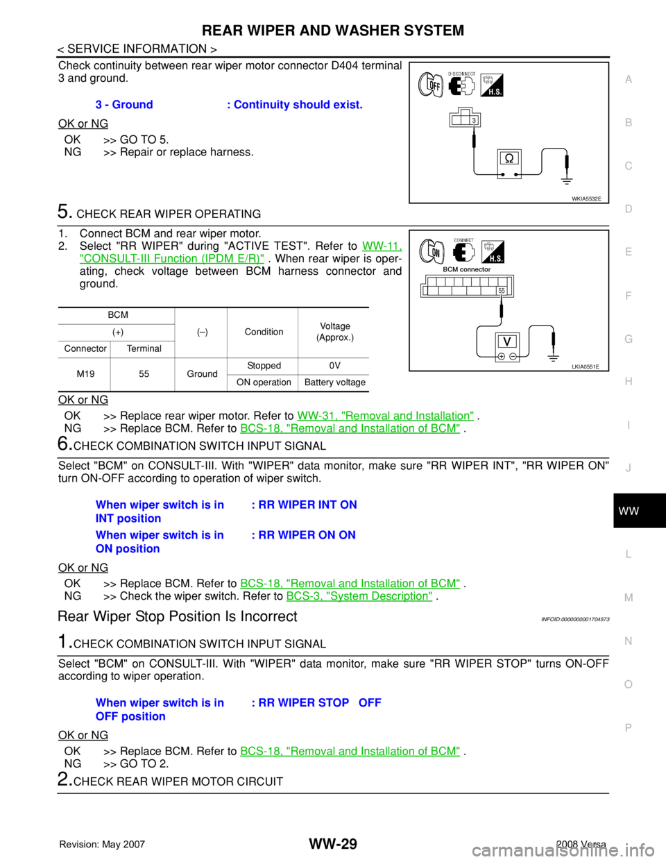
Check continuity between rear wiper motor connector D404 terminal
3 and ground.
OK or NG
OK >> GO TO 5.
NG >> Repair or replace harness.
5. CHECK REAR WIPER OPERATING
1. Connect BCM and rear wiper motor.
2. Select "RR WIPER" during "ACTIVE TEST". Refer to WW-11,
"CONSULT-III Function (IPDM E/R)" . When rear wiper is oper-
ating, check voltage between BCM harness connector and
ground.
OK or NG
OK >> Replace rear wiper motor. Refer to WW-31, "Removal and Installation" .
NG >> Replace BCM. Refer to BCS-18, "
Removal and Installation of BCM" .
6.CHECK COMBINATION SWITCH INPUT SIGNAL
Select "BCM" on CONSULT-III. With "WIPER" data monitor, make sure "RR WIPER INT", "RR WIPER ON"
turn ON-OFF according to operation of wiper switch.
OK or NG
OK >> Replace BCM. Refer to BCS-18, "Removal and Installation of BCM" .
NG >> Check the wiper switch. Refer to BCS-3, "
System Description" .
Rear Wiper Stop Position Is IncorrectINFOID:0000000001704573
1.CHECK COMBINATION SWITCH INPUT SIGNAL
Select "BCM" on CONSULT-III. With "WIPER" data monitor, make sure "RR WIPER STOP" turns ON-OFF
according to wiper operation.
OK or NG
OK >> Replace BCM. Refer to BCS-18, "Removal and Installation of BCM" .
NG >> GO TO 2.
2.CHECK REAR WIPER MOTOR CIRCUIT3 - Ground : Continuity should exist.
WKIA5532E
BCM
(–) ConditionVo l ta g e
(Approx.) (+)
Connector Terminal
M19 55 GroundStopped 0V
ON operation Battery voltage
LKIA0551E
When wiper switch is in
INT position: RR WIPER INT ON
When wiper switch is in
ON position: RR WIPER ON ON
When wiper switch is in
OFF position: RR WIPER STOP OFF
Page 2763 of 2771

WW-30
< SERVICE INFORMATION >
REAR WIPER AND WASHER SYSTEM
1. Turn ignition switch OFF.
2. Disconnect BCM and rear wiper motor.
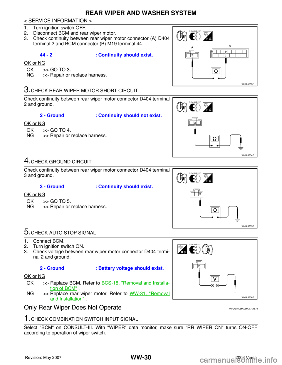
3. Check continuity between rear wiper motor connector (A) D404
terminal 2 and BCM connector (B) M19 terminal 44.
OK or NG
OK >> GO TO 3.
NG >> Repair or replace harness.
3.CHECK REAR WIPER MOTOR SHORT CIRCUIT
Check continuity between rear wiper motor connector D404 terminal
2 and ground.
OK or NG
OK >> GO TO 4.
NG >> Repair or replace harness.
4.CHECK GROUND CIRCUIT
Check continuity between rear wiper motor connector D404 terminal
3 and ground.
OK or NG
OK >> GO TO 5.
NG >> Repair or replace harness.
5.CHECK AUTO STOP SIGNAL
1. Connect BCM.
2. Turn ignition switch ON.
3. Check voltage between rear wiper motor connector D404 termi-
nal 2 and ground.
OK or NG
OK >> Replace BCM. Refer to BCS-18, "Removal and Installa-
tion of BCM" .
NG >> Replace rear wiper motor. Refer to WW-31, "
Removal
and Installation" .
Only Rear Wiper Does Not OperateINFOID:0000000001704574
1.CHECK COMBINATION SWITCH INPUT SIGNAL
Select "BCM" on CONSULT-III. With "WIPER" data monitor, make sure "RR WIPER ON" turns ON-OFF
according to operation of wiper switch.44 - 2 : Continuity should exist.
WKIA5533E
2 - Ground : Continuity should not exist.
WKIA5534E
3 - Ground : Continuity should exist.
WKIA5535E
2 - Ground : Battery voltage should exist.
WKIA5536E