2008 NISSAN LATIO battery
[x] Cancel search: batteryPage 499 of 2771
REMOTE KEYLESS ENTRY SYSTEM
BL-65
< SERVICE INFORMATION >
C
D
E
F
G
H
J
K
L
MA
B
BL
N
O
P
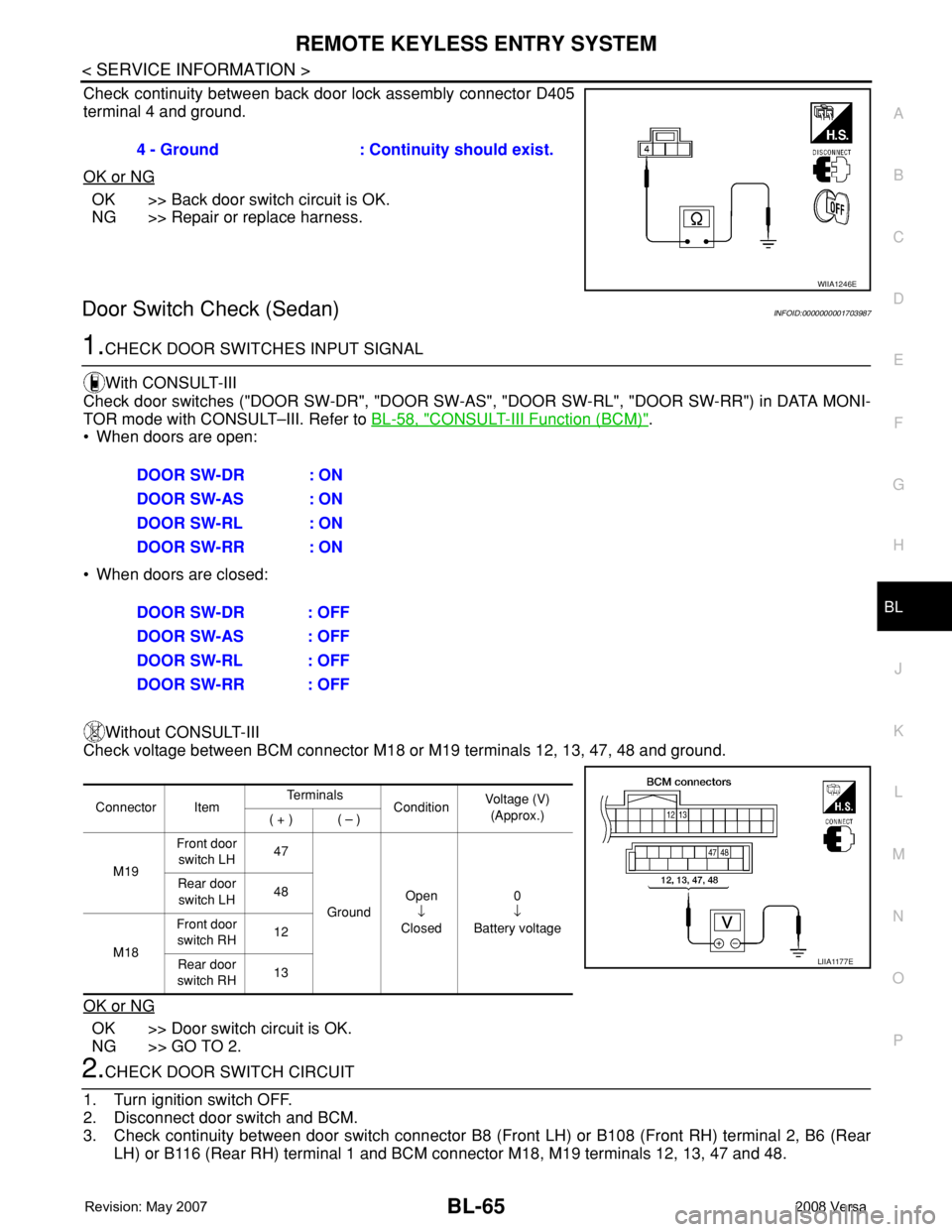
Check continuity between back door lock assembly connector D405
terminal 4 and ground.
OK or NG
OK >> Back door switch circuit is OK.
NG >> Repair or replace harness.
Door Switch Check (Sedan)INFOID:0000000001703987
1.CHECK DOOR SWITCHES INPUT SIGNAL
With CONSULT-III
Check door switches ("DOOR SW-DR", "DOOR SW-AS", "DOOR SW-RL", "DOOR SW-RR") in DATA MONI-
TOR mode with CONSULT–III. Refer to BL-58, "
CONSULT-III Function (BCM)".
• When doors are open:
• When doors are closed:
Without CONSULT-III
Check voltage between BCM connector M18 or M19 terminals 12, 13, 47, 48 and ground.
OK or NG
OK >> Door switch circuit is OK.
NG >> GO TO 2.
2.CHECK DOOR SWITCH CIRCUIT
1. Turn ignition switch OFF.
2. Disconnect door switch and BCM.
3. Check continuity between door switch connector B8 (Front LH) or B108 (Front RH) terminal 2, B6 (Rear
LH) or B116 (Rear RH) terminal 1 and BCM connector M18, M19 terminals 12, 13, 47 and 48.4 - Ground : Continuity should exist.
WIIA1246E
DOOR SW-DR : ON
DOOR SW-AS : ON
DOOR SW-RL : ON
DOOR SW-RR : ON
DOOR SW-DR : OFF
DOOR SW-AS : OFF
DOOR SW-RL : OFF
DOOR SW-RR : OFF
Connector ItemTe r m i n a l s
ConditionVoltage (V)
(Approx.)
( + ) ( – )
M19Front door
switch LH47
GroundOpen
↓
Closed0
↓
Battery voltage Rear door
switch LH48
M18Front door
switch RH12
Rear door
switch RH13
LIIA1177E
Page 501 of 2771
REMOTE KEYLESS ENTRY SYSTEM
BL-67
< SERVICE INFORMATION >
C
D
E
F
G
H
J
K
L
MA
B
BL
N
O
P
OK or NG
OK >> Key switch circuit is OK.
NG >> GO TO 2.
2.CHECK KEY SWITCH
1. Turn ignition switch OFF.
2. Disconnect key switch and key lock solenoid connector.
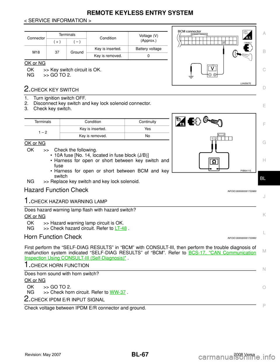
3. Check key switch.
OK or NG
OK >> Check the following.
• 10A fuse [No. 14, located in fuse block (J/B)]
• Harness for open or short between key switch and
fuse
• Harness for open or short between BCM and key
switch
NG >> Replace key switch and key lock solenoid.
Hazard Function CheckINFOID:0000000001703989
1.CHECK HAZARD WARNING LAMP
Does hazard warning lamp flash with hazard switch?
OK or NG
OK >> Hazard warning lamp circuit is OK.
NG >> Check hazard circuit. Refer to LT- 4 8
.
Horn Function CheckINFOID:0000000001703990
First perform the “SELF-DIAG RESULTS” in “BCM” with CONSULT-III, then perform the trouble diagnosis of
malfunction system indicated “SELF-DIAG RESULTS” of “BCM”. Refer to BCS-17, "
CAN Communication
Inspection Using CONSULT-III (Self-Diagnosis)" .
1.CHECK HORN FUNCTION
Does horn sound with horn switch?
OK or NG
OK >> GO TO 2.
NG >> Check horn circuit. Refer to WW-37
.
2.CHECK IPDM E/R INPUT SIGNAL
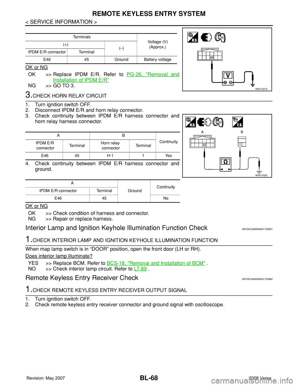
Check voltage between IPDM E/R connector and ground.
ConnectorTe r m i n a l s
ConditionVoltage (V)
(Approx.)
( + ) ( – )
M18 37 GroundKey is inserted. Battery voltage
Key is removed. 0
LIIA0567E
Terminals Condition Continuity
1 – 2Key is inserted. Yes
Key is removed. No
PIIB6411E
Page 502 of 2771
BL-68
< SERVICE INFORMATION >
REMOTE KEYLESS ENTRY SYSTEM
OK or NG
OK >> Replace IPDM E/R. Refer to PG-26, "Removal and
Installation of IPDM E/R"
NG >> GO TO 3.
3.CHECK HORN RELAY CIRCUIT
1. Turn ignition switch OFF.
2. Disconnect IPDM E/R and horn relay connector.
3. Check continuity between IPDM E/R harness connector and
horn relay harness connector.
4. Check continuity between IPDM E/R harness connector and
ground.
OK or NG
OK >> Check condition of harness and connector.
NG >> Repair or replace harness.
Interior Lamp and Ignition Keyhole Illumination Function CheckINFOID:0000000001703991
1.CHECK INTERIOR LAMP AND IGNITION KEYHOLE ILLUMINATION FUNCTION
When map lamp switch is in “DOOR” position, open the front door (LH or RH).
Does interior lamp illuminate?
YES >> Replace BCM. Refer to BCS-18, "Removal and Installation of BCM" .
NO >> Check interior lamp circuit. Refer to LT- 8 9
.
Remote Keyless Entry Receiver CheckINFOID:0000000001703992
1.CHECK REMOTE KEYLESS ENTRY RECEIVER OUTPUT SIGNAL
1. Turn ignition switch OFF.
2. Check remote keyless entry receiver connector and ground signal with oscilloscope.
Te r m i n a l s
Voltage (V)
(Approx.) (+)
(–)
IPDM E/R connector Terminal
E46 45 Ground Battery voltage
WIIA1251E
AB
Continuity
IPDM E/R
connectorTe r m i n a lHorn relay
connectorTe r m i n a l
E46 45 H-1 1 Yes
A
GroundContinuity
IPDM E/R connector Terminal
E46 45 No
WIIA1252E
Page 507 of 2771
REMOTE KEYLESS ENTRY SYSTEM
BL-73
< SERVICE INFORMATION >
C
D
E
F
G
H
J
K
L
MA
B
BL
N
O
P
To erase all ID codes in memory, register one ID code (keyfob) five times. After all ID codes are erased, the
ID codes of all remaining and/or new keyfobs must be re-registered.
• When registering an additional keyfob, the existing ID codes in memory may or may not be erased. If five ID
codes are stored in memory, when an additional code is registered, only the oldest code is erased. If less
than five ID codes are stored in memory, when an additional ID code is registered, the new ID code is added
and no ID codes are erased.
• If you need to activate more than two additional new keyfobs, repeat the procedure “Additional ID code
entry” for each new keyfob.
• Entry of maximum five ID codes is allowed. When more than five ID codes are entered, the oldest ID code
will be erased.
• Even if same ID code that is already in the memory is input, the same ID code can be entered. The code is
counted as an additional code.
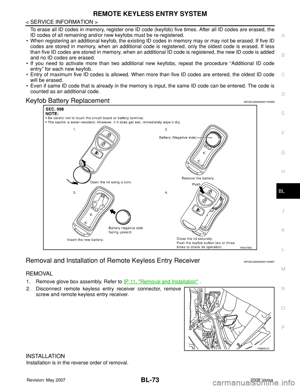
Keyfob Battery ReplacementINFOID:0000000001703996
Removal and Installation of Remote Keyless Entry ReceiverINFOID:0000000001703997
REMOVAL
1. Remove glove box assembly. Refer to IP-11, "Removal and Installation" .
2. Disconnect remote keyless entry receiver connector, remove
screw and remote keyless entry receiver.
INSTALLATION
Installation is in the reverse order of removal.
PIIA4706E
PIIB6541E
Page 510 of 2771
BL-76
< SERVICE INFORMATION >
INTELLIGENT KEY SYSTEM
System Description
INFOID:0000000001703999
• The Intelligent Key system is a system that makes it possible to lock and unlock the door locks (door lock/
unlock function), and start the engine (engine start function) by carrying around the Intelligent Key (without
some key operation), which operates based on the results of electronic ID verification using two-way com-
munications between the Intelligent Key and the vehicle (Intelligent Key unit).
• Vehicles equipped with a manual transmission include a key interlock solenoid located in the steering col-
umn to prevent accidental shut-off of the ignition switch and locking of the steering wheel during driving con-
dition when the vehicle is moving.
CAUTION:
The driver should always carry the Intelligent Key
• Operation of the remote controller buttons on the Intelligent Key also provides the same functions as the
remote control entry system. (Remote keyless entry functions)
• If an action that does not meet the operating conditions of the Intelligent Key system is taken, the buzzer
goes off to inform the driver. (Warning chime functions)
• When a door lock is locked or unlocked with request switch or remote controller button operation, the hazard
lamps flash and the buzzer (outside vehicle) sounds (Hazard and buzzer reminder function).
• Even if the Intelligent Key battery is completely discharged, the door locks can be locked and unlocked and
the engine started with the mechanical key built into the Intelligent Key.
• The settings for each function can be changed with the CONSULT-III.
• If an Intelligent Key is lost, a new Intelligent Key can be registered. A maximum of 4 Intelligent Keys can be
registered.
• It has been made possible to diagnose the system and register an Intelligent Key with the CONSULT-III.
DOOR LOCK/UNLOCK FUNCTION
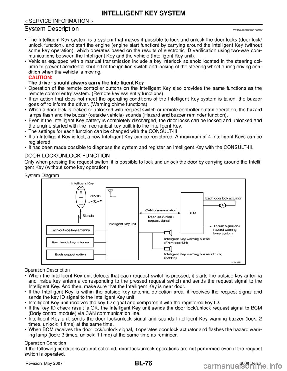
Only when pressing the request switch, it is possible to lock and unlock the door by carrying around the Intelli-
gent Key (without some key operation).
System Diagram
Operation Description
• When the Intelligent Key unit detects that each request switch is pressed, it starts the outside key antenna
and inside key antenna corresponding to the pressed request switch and sends the request signal to the
Intelligent Key. And then, make sure that the Intelligent Key is near door.
• If the Intelligent Key is within the outside key antenna detection area, it receives the request signal and
sends the key ID signal to the Intelligent Key unit.
• Intelligent Key unit receives the key ID signal and compares it with the registered key ID.
• If the key ID check result is OK, the Intelligent Key unit sends the door lock/unlock request signal to BCM
(Body control module) via CAN communication line.
• Intelligent Key unit sends the door lock/unlock signal and sounds Intelligent Key warning buzzer (lock: 2
times, unlock: 1 time) at the same time.
• When BCM receives the door lock/unlock signal, it operates door lock actuator and flashes the hazard warn-
ing lamp (lock: 2 times, unlock: 1 time) at the same time as reminder.
Operation Condition
If the following conditions are not satisfied, door lock/unlock operations are not performed even if the request
switch is operated.
LIIA2926E
Page 515 of 2771

INTELLIGENT KEY SYSTEM
BL-81
< SERVICE INFORMATION >
C
D
E
F
G
H
J
K
L
MA
B
BL
N
O
P
When ignition switch turns to START position, BCM sends starter request signal to IPDM E/R. Then, engine
starts.
Even if Intelligent Key battery runs down, Intelligent key unit can start engine with mechanical key built Intelli-
gent Key. For details, refer toBL-210
.
All of the originally supplied Intelligent Key IDs (except for key) have been registered in Intelligent Key system.
If requested by the vehicle owner, a maximum of four Intelligent Key IDs can be registered into the Intelligent
Key system components.
List of Operation Related Parts
Parts marked with × are the parts related to operation.
WARNING CHIME/BUZZER/LAMPS FUNCTION
Operation Description
The following warning chime (combination meter), Intelligent Key warning buzzer (front door LH), Intelligent
Key warning buzzer (trunk)
*, warning lamps "KEY" and “P-SHIFT” (with CVT) or "LOCK" (with M/T) are given
to the user as warning information while using the intelligent key system.
• Ignition switch warning chime
• Ignition key warning chime
• OFF position warning chime
• Take away warning chime
• Door lock operation warning chime
• Intelligent key low battery warning
• P position warning (with CVT)
• LOCK position warning (with M/T)
NOTE:
For key-in-ignition warning chime related concerns only, refer to DI-41
.
* :
Sedan
Operation Condition
Engine start functions
Intelligent Key
Key switch
Ignition knob switch
Inside key antenna
Intelligent Key unit
CAN communication system
BCM
Combination meter
IPDM E/R
NATS antenna amp.
Steering lock solenoid
Engine start function by the Intelligent Key××××××××× ×
Engine start function by the mechanical key× ××× ×××
Operation ConditionWarning chime/buzzer Warning lamp
Chime
(combina-
tion meter)Buzzer(s) KEYLOCK
(M/T)P-SHIFT
(CVT)
Ignition switch warning chime• Mechanical key is out of ignition switch
(Key switch is OFF)
• Ignition switch is in the ACC, OFF or
LOCK position.
[ignition switch is pressed
(ignition knob switch is ON).]
• Driver door is open.activate — — — —
Ignition key warning chime
(When mechanical key is used)• Mechanical key is inserted in ignition
switch (key switch is ON).
• Ignition switch is in the ACC, OFF or
LOCK position.
• Driver door is open.activate — — — —
Page 516 of 2771

BL-82
< SERVICE INFORMATION >
INTELLIGENT KEY SYSTEM
List of Operation Related Parts
Parts marked with × are the parts related to operation.
P position warning (CVT)When selector lever is in other than P po-
sition, ignition switch is turned from ON to
OFF.activate — — — Flash
OFF position warn-
ing chimeFor internal• Ignition switch is turned from ACC to
OFF.
[ignition switch is pressed (ignition knob
switch is ON).]
• Ignition switch is in the LOCK position
and pressed for 1 second.activate — — Flash —
For externalWhen driver door is opened and then
closed while the OFF position warning
chime above is operating—activate—— —
Ta k e a w a y w a r n i n gRight after
door is closedRight after door is closed and the following
conditions are met.
• Ignition knob is pressed and in rotatable
or rotated state
• Intelligent Key can not be detected in-
side the vehicle—activateFlash
(red)——
Any door is
openedAny door is opened and the following con-
ditions are met.
• Ignition knob is pressed and in rotatable
or rotated state
• Intelligent Key unit will perform key ID
verification with Intelligent Key through
inside key antenna every 5 second, if
the key ID verification is NG.——Flash
(red)——
Ta k e a w a y
from the win-
dowTake away from the window and the fol-
lowing conditions are met.
• Ignition knob is pressed and in rotatable
or rotated state
• Vehicle speed below 5 km/h (3 m.p.h.)
• Intelligent Key unit will perform key ID
verification with Intelligent Key through
inside key antenna every 30 second, if
the key ID verification is NG.
(This warning function will be disabled if
mechanical key is inserted into the key
cylinder.)
NOTE:
Default setting of this function is OFF.activate —Flash
(red)——
Door lock opera-
tion warningLock opera-
tion with re-
quest switchLock operation with request switch and
the following condition is met.
• Intelligent Key is inside the vehicle—activate—— —
Intelligent Key low battery warningWhen Intelligent Key is low battery, Intelli-
gent Key unit is detected after ignition
switch is turned ON.——Flash
(green)—— Operation ConditionWarning chime/buzzer Warning lamp
Chime
(combina-
tion meter)Buzzer(s) KEYLOCK
(M/T)P-SHIFT
(CVT)
Page 517 of 2771

INTELLIGENT KEY SYSTEM
BL-83
< SERVICE INFORMATION >
C
D
E
F
G
H
J
K
L
MA
B
BL
N
O
P
CHANGE SETTINGS FUNCTION
The settings for each function can be changed with the CONSULT-III.
Changing Settings Using CONSULT-III
The settings for the Intelligent Key system functions can be changed using CONSULT-III (WORK SUPPORT).
Refer to BL-101, "
CONSULT-III Application Item".
NOTE:
Once a function setting is changed, it will remain effective even if the battery is disconnected.
INTELLIGENT KEY REGISTRATION
Intelligent Key-ID registration is performed using the CONSULT-III.
CAUTION:
• After a new Intelligent Key-ID is registered, be sure to check the function.
• When registering an additional Intelligent Key-ID, take any Intelligent Keys already registered and
Intelligent Keys for any other vehicles out of the vehicle before starting.
CONSULT-III can be used to check and delete Intelligent Key-IDs.
For further information, see the CONSULT-III Operation Manual NATS.
STEERING LOCK SOLENOID REGISTRATION
Steering Lock Solenoid ID Registration
CAUTION:
• The method for registering a steering lock solenoid ID depends on the status of the steering lock
solenoid and Intelligent Key unit (new or old unit).
• After registration is completed, press ignition switch with an Intelligent Key in the vehicle so that it
can be turned, and confirm that it cannot be turned even when ignition switch is pressed without an
Intelligent Key in the vehicle.
For further information, see the CONSULT-III Operation Manual NATS-IVIS/NVIS.
CAN Communication System DescriptionINFOID:0000000001704000
Refer to LAN-6.
Warning and alarm functions
Intelligent Key
Key switch
Ignition knob switch
Ignition switch ACC position input signal
Ignition switch ON position input signal
Door switch
Door request switch
Inside key antenna
Outside key antenna (Driver, Passenger)
Outside key antenna (rear bumper)
Intelligent Key warning buzzer(s)
Intelligent Key unit
CAN communication system
BCM
Warning lamp
Warning chime (combination meter)
Ignition switch warning chime× ×× ××× ×
Ignition key warning chime
(When mechanical key used)××× ×××
OFF position warning chimeFor internal××× ××××××
For external×××× ×××××
Take away warning chimeRight after door is
closed××× × × ×××××
Any door is open××× × × ××××
Take away from
window××× × × ××××××
Door lock operation warning chime× ××××××××
Intelligent Key low battery warning××××××