2008 NISSAN LATIO oil temperature
[x] Cancel search: oil temperaturePage 16 of 2771

AT-4
Diagnosis Procedure .............................................210
KEY INTERLOCK CABLE ...............................213
Removal and Installation .......................................213
ON-VEHICLE SERVICE ..................................216
Control Valve Assembly and Accumulators ...........216
Park/Neutral Position (PNP) Switch ......................219
Revolution Sensor .................................................221
Turbine Revolution Sensor (Power Train Revolu-
tion Sensor) ...........................................................
222
Differential Side Oil Seal ........................................223
AIR BREATHER HOSE ...................................225
Removal and Installation .......................................225
TRANSAXLE ASSEMBLY ..............................226
Removal and Installation .......................................226
OVERHAUL .....................................................230
Component ............................................................230
Oil Channel ............................................................237
Location of Adjusting Shims, Needle Bearings and
Thrust Washers .....................................................
238
Location of Snap Rings .........................................239
DISASSEMBLY ...............................................240
Disassembly ..........................................................240
REPAIR FOR COMPONENT PARTS ..............257
Manual Shaft .........................................................257
Oil Pump ................................................................260
Control Valve Assembly ........................................263
Control Valve Upper Body .....................................272
Control Valve Lower Body .....................................276
Reverse Clutch ......................................................279
High Clutch ............................................................284
Forward and Overrun Clutches .............................288
Low & Reverse Brake ............................................295
Rear Internal Gear and Forward Clutch Hub .........299
Output Shaft, Output Gear, Idler Gear, Reduction
Pinion Gear and Bearing Retainer .........................
302
Band Servo Piston Assembly ................................307
Final Drive .............................................................313
ASSEMBLY ......................................................318
Assembly (1) .........................................................318
Adjustment (1) .......................................................319
Assembly (2) .........................................................325
Adjustment (2) .......................................................330
Assembly (3) .........................................................333
SERVICE DATA AND SPECIFICATIONS
(SDS) ................................................................
341
General Specification ............................................341
Vehicle Speed at Which Gear Shifting Occurs .....341
Vehicle Speed at When Lock-up Occurs/Releases
.
341
Stall Speed ............................................................341
Line Pressure ........................................................341
Adjusting shims, Needle Bearings, Thrust Wash-
ers and Snap Rings ..............................................
341
Control Valves .......................................................343
Accumulator ..........................................................343
Clutches and Brakes .............................................343
Final Drive .............................................................345
Planetary Carrier ...................................................345
Oil Pump ...............................................................345
Input Shaft .............................................................345
Reduction Pinion Gear ..........................................345
Band Servo ...........................................................345
Output Shaft ..........................................................346
Bearing Retainer ...................................................346
Total End Play .......................................................346
Reverse Clutch End Play ......................................346
Removal and Installation .......................................346
Shift Solenoid Valves ............................................346
Solenoid Valves ....................................................346
A/T Fluid Temperature Sensor ..............................347
Revolution Sensor .................................................347
Dropping Resistor .................................................347
Turbine Revolution Sensor (Power Train Revolu-
tion Sensor) ...........................................................
347
Page 43 of 2771
A/T CONTROL SYSTEM
AT-31
< SERVICE INFORMATION >
D
E
F
G
H
I
J
K
L
MA
B
AT
N
O
P
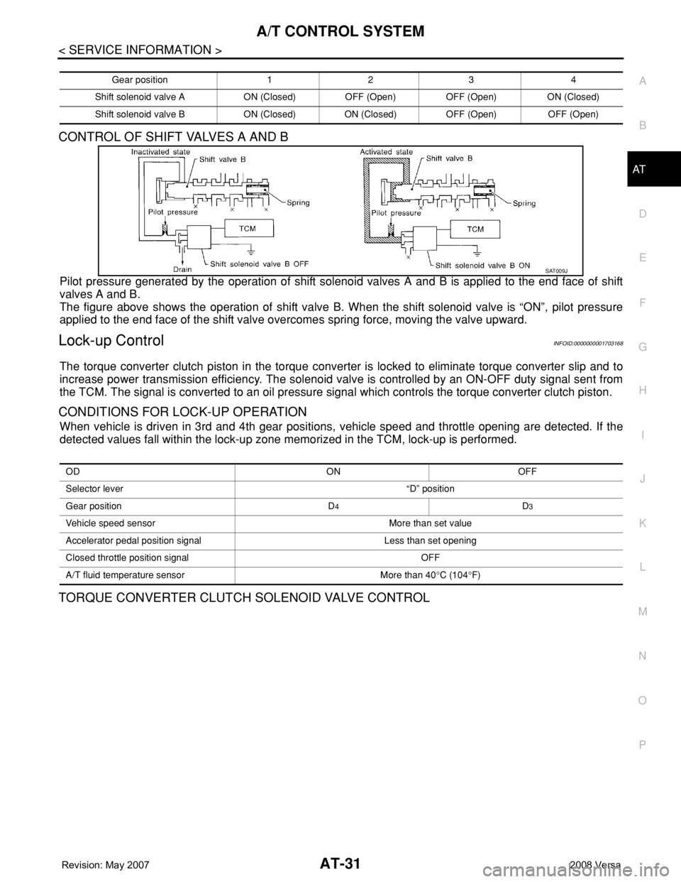
CONTROL OF SHIFT VALVES A AND B
Pilot pressure generated by the operation of shift solenoid valves A and B is applied to the end face of shift
valves A and B.
The figure above shows the operation of shift valve B. When the shift solenoid valve is “ON”, pilot pressure
applied to the end face of the shift valve overcomes spring force, moving the valve upward.
Lock-up ControlINFOID:0000000001703168
The torque converter clutch piston in the torque converter is locked to eliminate torque converter slip and to
increase power transmission efficiency. The solenoid valve is controlled by an ON-OFF duty signal sent from
the TCM. The signal is converted to an oil pressure signal which controls the torque converter clutch piston.
CONDITIONS FOR LOCK-UP OPERATION
When vehicle is driven in 3rd and 4th gear positions, vehicle speed and throttle opening are detected. If the
detected values fall within the lock-up zone memorized in the TCM, lock-up is performed.
TORQUE CONVERTER CLUTCH SOLENOID VALVE CONTROL
Gear position 1 2 3 4
Shift solenoid valve A ON (Closed) OFF (Open) OFF (Open) ON (Closed)
Shift solenoid valve B ON (Closed) ON (Closed) OFF (Open) OFF (Open)
SAT009J
OD ON OFF
Selector lever “D” position
Gear position D
4D3
Vehicle speed sensor More than set value
Accelerator pedal position signal Less than set opening
Closed throttle position signal OFF
A/T fluid temperature sensor More than 40°C (104°F)
Page 60 of 2771
AT-48
< SERVICE INFORMATION >
TROUBLE DIAGNOSIS
Inspections Before Trouble Diagnosis
INFOID:0000000001703182
A/T FLUID CHECK
Fluid Leakage and Fluid Level Check
Check fluid leakage and check the fluid level. Refer to MA-22, "Checking A/T Fluid".
Fluid Condition Check
Check the A/T fluid condition.
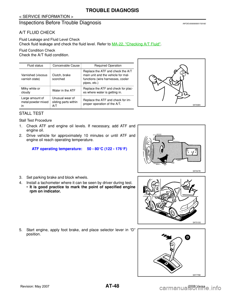
STALL TEST
Stall Test Procedure
1. Check ATF and engine oil levels. If necessary, add ATF and
engine oil.
2. Drive vehicle for approximately 10 minutes or until ATF and
engine oil reach operating temperature.
3. Set parking brake and block wheels.
4. Install a tachometer where it can be seen by driver during test.
•It is good practice to mark the point of specified engine
rpm on indicator.
5. Start engine, apply foot brake, and place selector lever in “D”
position.
Fluid status Conceivable Cause Required Operation
Varnished (viscous
varnish state)Clutch, brake
scorchedReplace the ATF and check the A/T
main unit and the vehicle for mal-
functions (wire harnesses, cooler
pipes, etc.)
Milky white or
cloudyWater in the ATFReplace the ATF and check for plac-
es where water is getting in.
Large amount of
metal powder mixed
inUnusual wear of
sliding parts within
A/TReplace the ATF and check for im-
proper operation of the A/T.
SAT638A
ATF operating temperature: 50 - 80°C (122 - 176°F)
SAT647B
SAT513G
SAT775B
Page 63 of 2771
TROUBLE DIAGNOSIS
AT-51
< SERVICE INFORMATION >
D
E
F
G
H
I
J
K
L
MA
B
AT
N
O
P
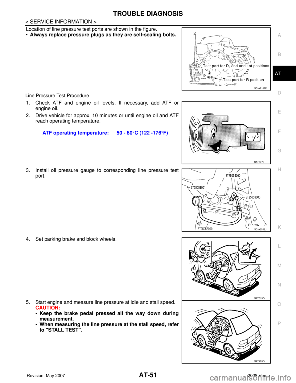
Location of line pressure test ports are shown in the figure.
•Always replace pressure plugs as they are self-sealing bolts.
Line Pressure Test Procedure
1. Check ATF and engine oil levels. If necessary, add ATF or
engine oil.
2. Drive vehicle for approx. 10 minutes or until engine oil and ATF
reach operating temperature.
3. Install oil pressure gauge to corresponding line pressure test
port.
4. Set parking brake and block wheels.
5. Start engine and measure line pressure at idle and stall speed.
CAUTION:
• Keep the brake pedal pressed all the way down during
measurement.
• When measuring the line pressure at the stall speed, refer
to "STALL TEST".
SCIA7187E
ATF operating temperature: 50 - 80°C (122 -176°F)
SAT647B
SCIA6528J
SAT513G
SAT493G
Page 64 of 2771
AT-52
< SERVICE INFORMATION >
TROUBLE DIAGNOSIS
Line Pressure
Judgement of Line Pressure Test
Road TestINFOID:0000000001703183
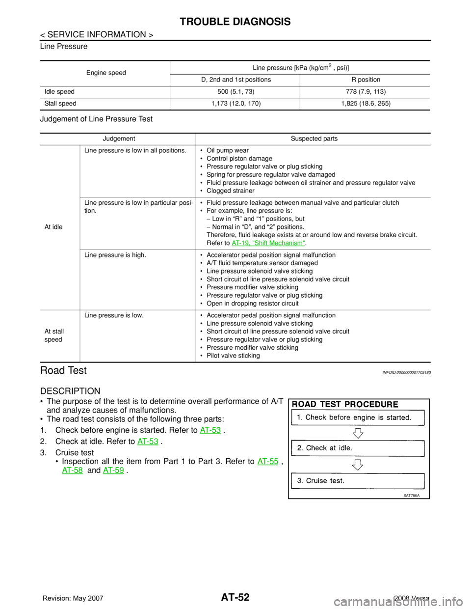
DESCRIPTION
• The purpose of the test is to determine overall performance of A/T
and analyze causes of malfunctions.
• The road test consists of the following three parts:
1. Check before engine is started. Refer to AT- 5 3
.
2. Check at idle. Refer to AT- 5 3
.
3. Cruise test
• Inspection all the item from Part 1 to Part 3. Refer to AT- 5 5
,
AT- 5 8
and AT- 5 9 .
Engine speedLine pressure [kPa (kg/cm
2 , psi)]
D, 2nd and 1st positions R position
Idle speed 500 (5.1, 73) 778 (7.9, 113)
Stall speed 1,173 (12.0, 170) 1,825 (18.6, 265)
Judgement Suspected parts
At idleLine pressure is low in all positions. • Oil pump wear
• Control piston damage
• Pressure regulator valve or plug sticking
• Spring for pressure regulator valve damaged
• Fluid pressure leakage between oil strainer and pressure regulator valve
• Clogged strainer
Line pressure is low in particular posi-
tion.• Fluid pressure leakage between manual valve and particular clutch
• For example, line pressure is:
− Low in “R” and “1” positions, but
− Normal in “D”, and “2” positions.
Therefore, fluid leakage exists at or around low and reverse brake circuit.
Refer to AT- 1 9 , "
Shift Mechanism".
Line pressure is high. • Accelerator pedal position signal malfunction
• A/T fluid temperature sensor damaged
• Line pressure solenoid valve sticking
• Short circuit of line pressure solenoid valve circuit
• Pressure modifier valve sticking
• Pressure regulator valve or plug sticking
• Open in dropping resistor circuit
At stall
speedLine pressure is low. • Accelerator pedal position signal malfunction
• Line pressure solenoid valve sticking
• Short circuit of line pressure solenoid valve circuit
• Pressure regulator valve or plug sticking
• Pressure modifier valve sticking
• Pilot valve sticking
SAT786A
Page 67 of 2771
TROUBLE DIAGNOSIS
AT-55
< SERVICE INFORMATION >
D
E
F
G
H
I
J
K
L
MA
B
AT
N
O
P
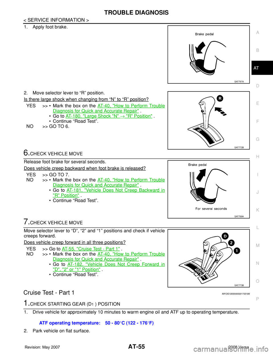
1. Apply foot brake.
2. Move selector lever to “R” position.
Is there large shock when changing from
“N” to “R” position?
YES >> • Mark the box on the AT-40, "How to Perform Trouble
Diagnosis for Quick and Accurate Repair" .
•Go to AT-180, "
Large Shock "N" → "R" Position" .
• Continue “Road Test”.
NO >> GO TO 6.
6.CHECK VEHICLE MOVE
Release foot brake for several seconds.
Does vehicle creep backward when foot brake is released?
YES >> GO TO 7.
NO >> • Mark the box on the AT-40, "
How to Perform Trouble
Diagnosis for Quick and Accurate Repair" .
•Go to AT-181, "
Vehicle Does Not Creep Backward in
"R" Position" .
• Continue “Road Test”.
7.CHECK VEHICLE MOVE
Move selector lever to “D”, “2” and “1” positions and check if vehicle
creeps forward.
Does vehicle creep forward in all three positions?
YES >> Go to AT-55, "Cruise Test - Part 1" .
NO >> • Mark the box on the AT-40, "
How to Perform Trouble
Diagnosis for Quick and Accurate Repair" .
•Go to AT-182, "
Vehicle Does Not Creep Forward in
"D", "2" or "1" Position" .
• Continue “Road Test”.
Cruise Test - Part 1INFOID:0000000001703186
1.CHECK STARTING GEAR (D1 ) POSITION
1. Drive vehicle for approximately 10 minutes to warm engine oil and ATF up to operating temperature.
2. Park vehicle on flat surface.
SAT797A
SAT772B
SAT799A
SAT773B
ATF operating temperature: 50 - 80°C (122 - 176°F)
Page 106 of 2771
AT-94
< SERVICE INFORMATION >
DTC P0710 A/T FLUID TEMPERATURE SENSOR CIRCUIT
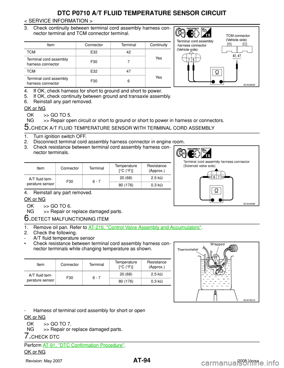
3. Check continuity between terminal cord assembly harness con-
nector terminal and TCM connector terminal.
4. If OK, check harness for short to ground and short to power.
5. If OK, check continuity between ground and transaxle assembly.
6. Reinstall any part removed.
OK or NG
OK >> GO TO 5.
NG >> Repair open circuit or short to ground or short to power in harness or connectors.
5.CHECK A/T FLUID TEMPERATURE SENSOR WITH TERMINAL CORD ASSEMBLY
1. Turn ignition switch OFF.
2. Disconnect terminal cord assembly harness connector in engine room.
3. Check resistance between terminal cord assembly harness con-
nector terminals.
4. Reinstall any part removed.
OK or NG
OK >> GO TO 6.
NG >> Repair or replace damaged parts.
6.DETECT MALFUNCTIONING ITEM
1. Remove oil pan. Refer to AT-216, "
Control Valve Assembly and Accumulators".
2. Check the following.
- A/T fluid temperature sensor
• Check resistance between terminal cord assembly harness con-
nector terminals while changing temperature as shown.
- Harness of terminal cord assembly for short or open
OK or NG
OK >> GO TO 7.
NG >> Repair or replace damaged parts.
7.CHECK DTC
Perform AT-91, "
DTC Confirmation Procedure".
OK or NG
Item Connector Terminal Continuity
TCM E32 42
Ye s
Terminal cord assembly
harness connectorF30 7
TCM E32 47
Ye s
Terminal cord assembly
harness connectorF30 6
SCIA2660E
Item Connector Terminal Temperature
[°C (°F)]Resistance
(Approx.)
A/T fluid tem-
perature sensorF30 6 - 720 (68) 2.5 kΩ
80 (176) 0.3 kΩ
SCIA4948E
Item Connector Terminal Temperature
[°C (°F)]Resistance
(Approx.)
A/T fluid tem-
perature sensorF30 6 - 720 (68) 2.5 kΩ
80 (176) 0.3 kΩ
SCIA7831E
Page 107 of 2771
DTC P0710 A/T FLUID TEMPERATURE SENSOR CIRCUIT
AT-95
< SERVICE INFORMATION >
D
E
F
G
H
I
J
K
L
MA
B
AT
N
O
P
OK >>INSPECTION END
NG >> GO TO 8.
8.CHECK TCM
1. Check TCM input/output signal. Refer to AT-71, "
TCM Terminal and Reference Value".
2. If NG, recheck TCM pin terminals for damage or loose connection with harness connector.
OK or NG
OK >>INSPECTION END
NG >> Repair or replace damaged parts.
Component InspectionINFOID:0000000001703216
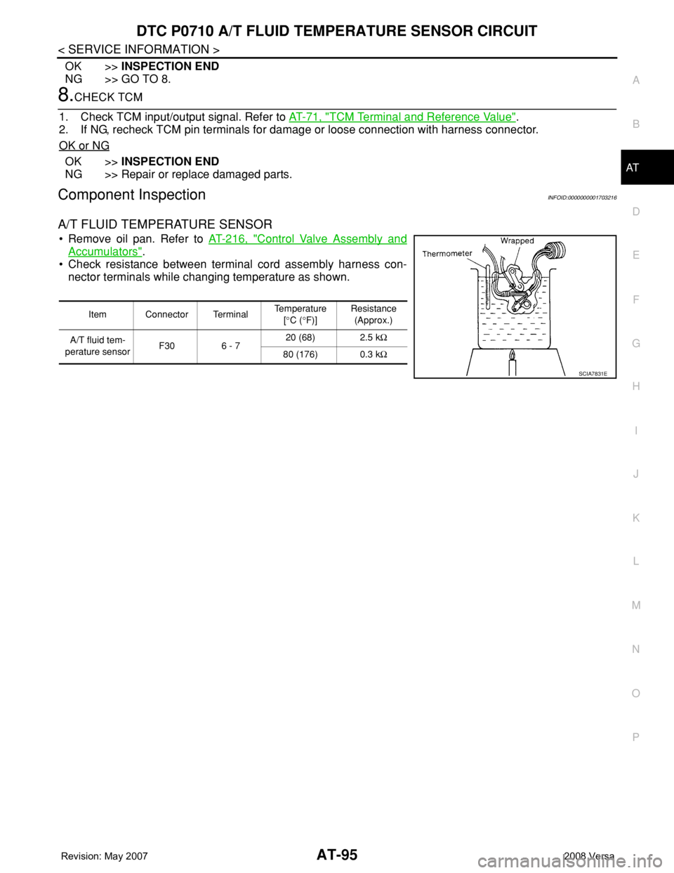
A/T FLUID TEMPERATURE SENSOR
• Remove oil pan. Refer to AT-216, "Control Valve Assembly and
Accumulators".
• Check resistance between terminal cord assembly harness con-
nector terminals while changing temperature as shown.
Item Connector Terminal Temperature
[°C (°F)]Resistance
(Approx.)
A/T fluid tem-
perature sensorF30 6 - 720 (68) 2.5 kΩ
80 (176) 0.3 kΩ
SCIA7831E