2008 NISSAN LATIO oil temperature
[x] Cancel search: oil temperaturePage 868 of 2771

TROUBLE DIAGNOSIS
CVT-29
< SERVICE INFORMATION >
D
E
F
G
H
I
J
K
L
MA
B
CVT
N
O
P
TROUBLE DIAGNOSIS
DTC Inspection Priority ChartINFOID:0000000001703451
If some DTCs are displayed at the same time, perform inspections one by one based on the following priority
chart.
NOTE:
If DTC “U1000 CAN COMM CIRCUIT” is displayed with other DTCs, first perform the trouble diagnosis
for “DTC U1000 CAN COMMUNICATION LINE”. Refer to CVT-56
.
Fail-SafeINFOID:0000000001703452
The TCM has an electrical fail-safe mode. This mode makes it possible to operate even if there is an error in a
main electronic control input/output signal circuit.
FAIL-SAFE FUNCTION
If any malfunction occurs in a sensor or solenoid, this function controls the CVT to make driving possible.
Output Speed Sensor (Secondary Speed Sensor)
The shift pattern is changed in accordance with throttle position when an unexpected signal is sent from the
output speed sensor (secondary speed sensor) to the TCM. The overdrive-off mode is inhibited, and the tran-
saxle is put in “D”.
Input Speed Sensor (Primary Speed Sensor)
The shift pattern is changed in accordance with throttle position and secondary speed (vehicle speed) when
an unexpected signal is sent from the input speed sensor (primary speed sensor) to the TCM. The sport mode
is inhibited, and the transaxle is put in “D”.
PNP Switch
If an unexpected signal is sent from the PNP switch to the TCM, the transaxle is put in “D”.
CVT Fluid Temperature Sensor
If an unexpected signal is sent from the CVT fluid temperature sensor to the TCM, the gear ratio in use before
receiving the unexpected signal is maintained or the gear ratio is controlled to keep engine speed under 3500
rpm.
Transmission Fluid Pressure Sensor A (Secondary Pressure Sensor)
• If an unexpected signal is sent from the transmission fluid pressure sensor A (secondary pressure sensor) to
the TCM, the secondary pressure feedback control is stopped and the offset value obtained before the non-
standard condition occurs is used to control line pressure.
• If transmission fluid pressure sensor A (secondary pressure sensor) error signal is input to TCM, secondary
pressure feedback control stops, but line pressure is controlled normally.
Pressure Control Solenoid A (Line Pressure Solenoid)
If an unexpected signal is sent from the solenoid to the TCM, the pressure control solenoid A (line pressure
solenoid) is turned OFF to achieve the maximum fluid pressure.
Pressure Control Solenoid B (Secondary Pressure Solenoid)
If an unexpected signal is sent from the solenoid to the TCM, the pressure control solenoid B (secondary pres-
sure solenoid) is turned OFF to achieve the maximum fluid pressure.
Torque Converter Clutch Solenoid
If an unexpected signal is sent from the solenoid to the TCM, the torque converter clutch solenoid is turned
OFF to cancel the lock-up.
Ste p M oto r
If an unexpected signal is sent from the step motor to the TCM, the step motor coil phases “A” through “D” are
all turned OFF to hold the gear ratio used right before the non-standard condition occurred.
CVT Lock-up Select Solenoid
Priority Detected items (DTC)
1 U1000 CAN communication line
2 Except above
Page 876 of 2771
TROUBLE DIAGNOSIS
CVT-37
< SERVICE INFORMATION >
D
E
F
G
H
I
J
K
L
MA
B
CVT
N
O
P
• Inspect for fluid leakage and check the fluid level. Refer to MA-19, "Checking CVT Fluid" .
Fluid Condition Check
Inspect the fluid condition.
STALL TEST
Stall Test Procedure
1. Inspect the amount of engine oil. Replenish the engine oil if necessary.
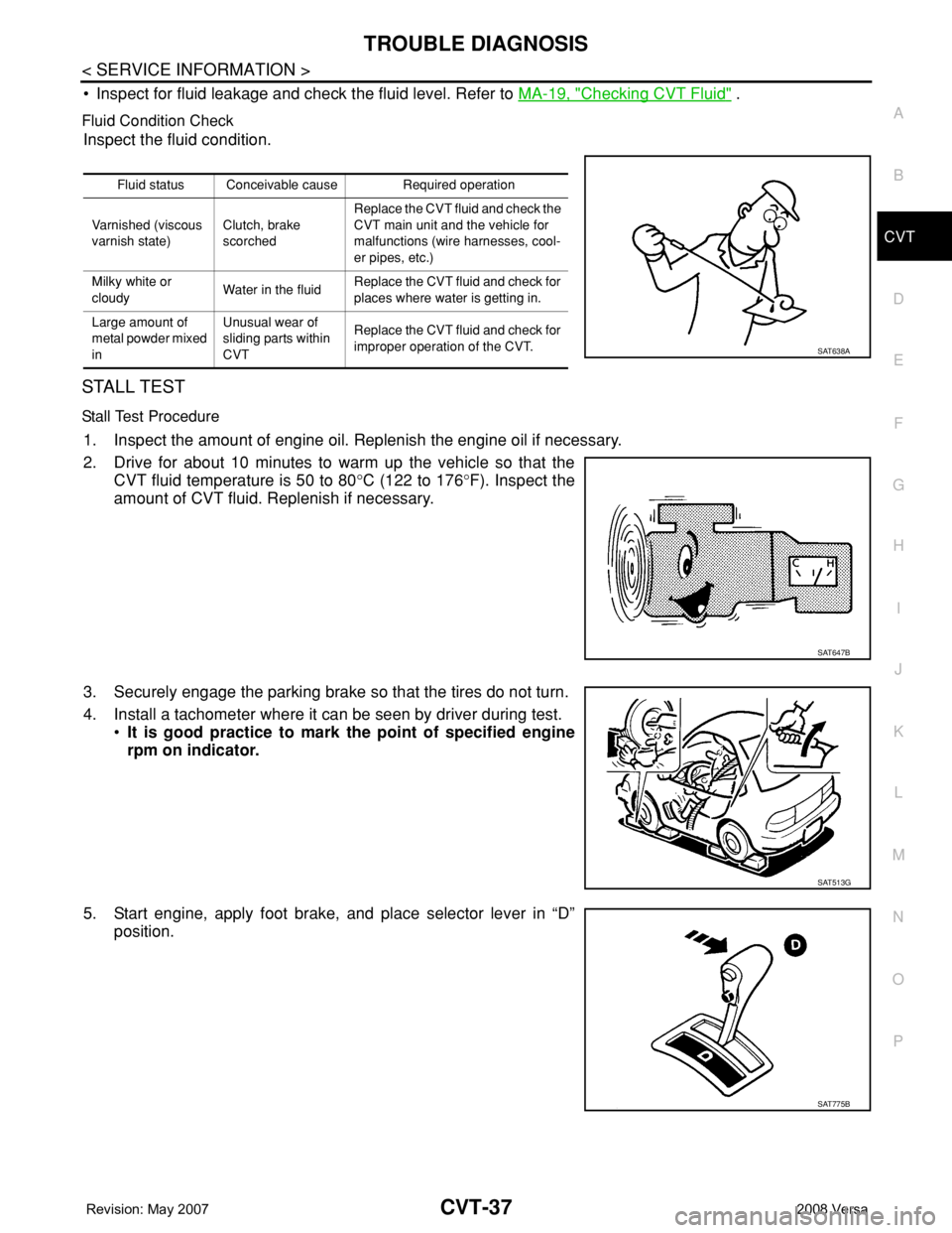
2. Drive for about 10 minutes to warm up the vehicle so that the
CVT fluid temperature is 50 to 80°C (122 to 176°F). Inspect the
amount of CVT fluid. Replenish if necessary.
3. Securely engage the parking brake so that the tires do not turn.
4. Install a tachometer where it can be seen by driver during test.
•It is good practice to mark the point of specified engine
rpm on indicator.
5. Start engine, apply foot brake, and place selector lever in “D”
position.
Fluid status Conceivable cause Required operation
Varnished (viscous
varnish state)Clutch, brake
scorchedReplace the CVT fluid and check the
CVT main unit and the vehicle for
malfunctions (wire harnesses, cool-
er pipes, etc.)
Milky white or
cloudyWater in the fluidReplace the CVT fluid and check for
places where water is getting in.
Large amount of
metal powder mixed
inUnusual wear of
sliding parts within
CVTReplace the CVT fluid and check for
improper operation of the CVT.
SAT638A
SAT647B
SAT513G
SAT775B
Page 878 of 2771
TROUBLE DIAGNOSIS
CVT-39
< SERVICE INFORMATION >
D
E
F
G
H
I
J
K
L
MA
B
CVT
N
O
P
The CVT fluid temperature rises in the range of 50 - 80°C (122 - 176°F) during 10 minutes of driving.
3. After warming up CVT, remove the oil pressure detection plug and install the oil pressure gauge [special
service tool: - (OTC3492)].
CAUTION:
When using the oil pressure gauge, be sure to use the O-ring attached to the oil pressure detec-
tion plug.
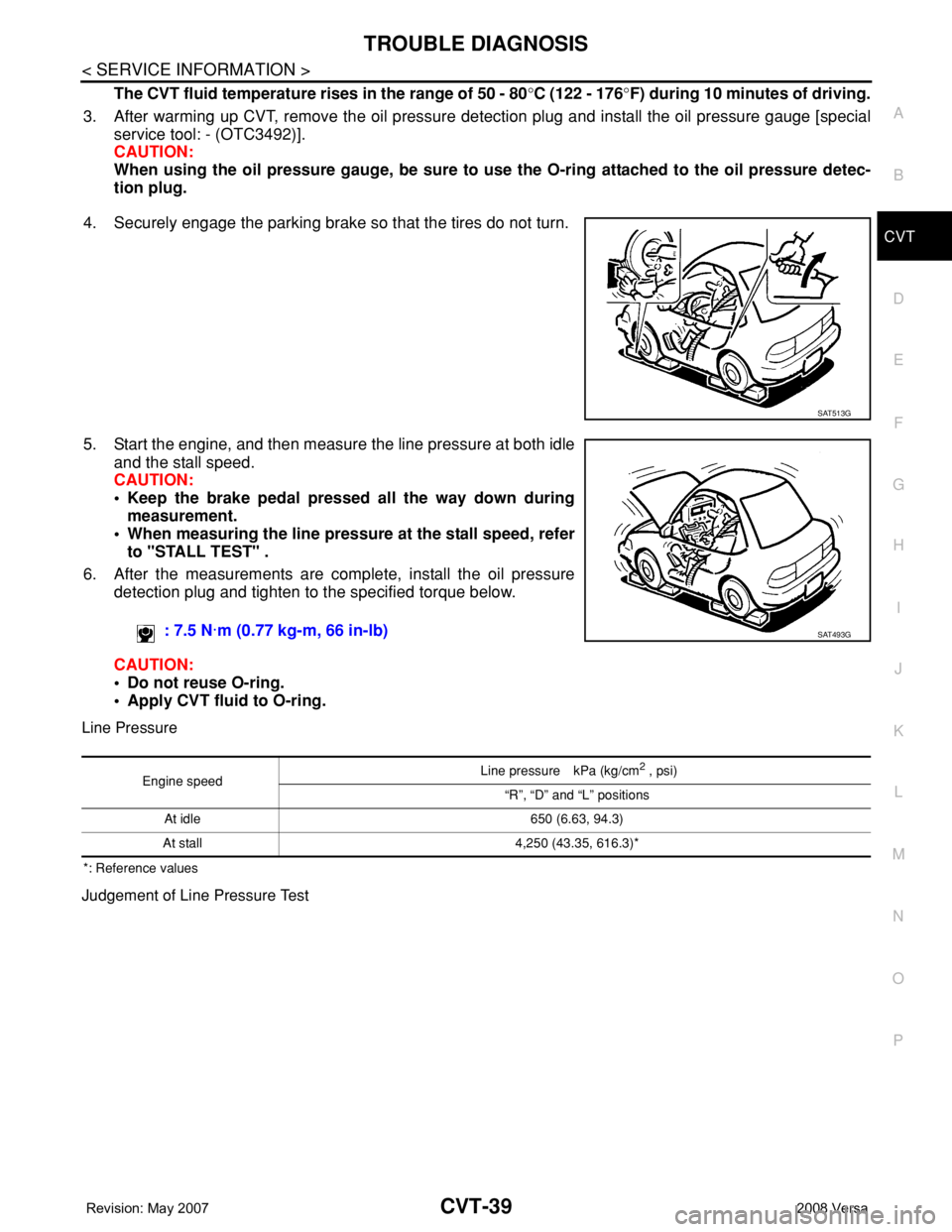
4. Securely engage the parking brake so that the tires do not turn.
5. Start the engine, and then measure the line pressure at both idle
and the stall speed.
CAUTION:
• Keep the brake pedal pressed all the way down during
measurement.
• When measuring the line pressure at the stall speed, refer
to "STALL TEST" .
6. After the measurements are complete, install the oil pressure
detection plug and tighten to the specified torque below.
CAUTION:
• Do not reuse O-ring.
• Apply CVT fluid to O-ring.
Line Pressure
*: Reference values
Judgement of Line Pressure Test
SAT513G
: 7.5 N·m (0.77 kg-m, 66 in-lb)SAT493G
Engine speed Line pressure kPa (kg/cm
2 , psi)
“R”, “D” and “L” positions
At idle 650 (6.63, 94.3)
At stall 4,250 (43.35, 616.3)*
Page 879 of 2771
CVT-40
< SERVICE INFORMATION >
TROUBLE DIAGNOSIS
Road Test
INFOID:0000000001703457
DESCRIPTION
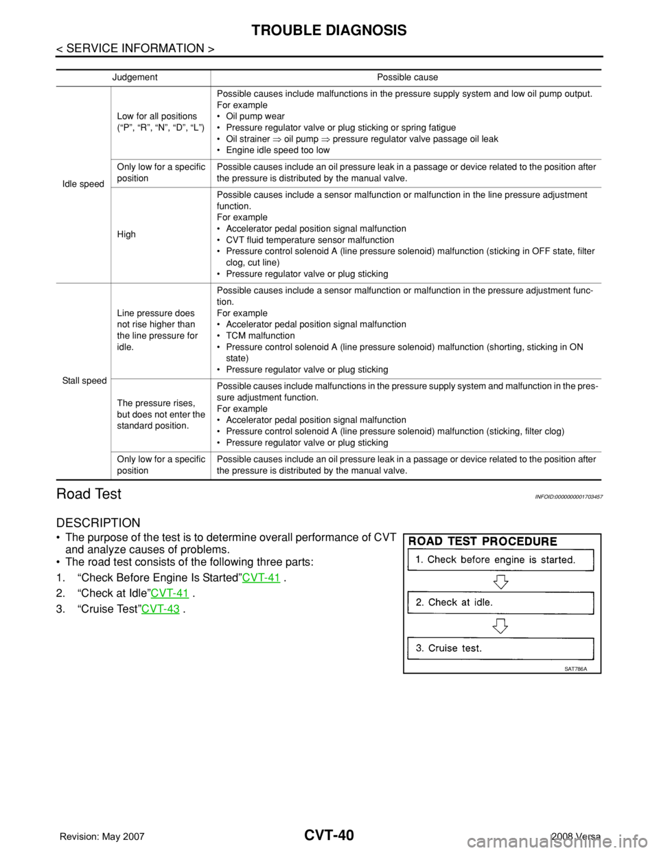
• The purpose of the test is to determine overall performance of CVT
and analyze causes of problems.
• The road test consists of the following three parts:
1. “Check Before Engine Is Started”CVT-41
.
2. “Check at Idle”CVT-41
.
3. “Cruise Test”CVT-43
.
Judgement Possible cause
Idle speedLow for all positions
(“P”, “R”, “N”, “D”, “L”)Possible causes include malfunctions in the pressure supply system and low oil pump output.
For example
•Oil pump wear
• Pressure regulator valve or plug sticking or spring fatigue
•Oil strainer ⇒ oil pump ⇒ pressure regulator valve passage oil leak
• Engine idle speed too low
Only low for a specific
positionPossible causes include an oil pressure leak in a passage or device related to the position after
the pressure is distributed by the manual valve.
HighPossible causes include a sensor malfunction or malfunction in the line pressure adjustment
function.
For example
• Accelerator pedal position signal malfunction
• CVT fluid temperature sensor malfunction
• Pressure control solenoid A (line pressure solenoid) malfunction (sticking in OFF state, filter
clog, cut line)
• Pressure regulator valve or plug sticking
Sta ll sp ee dLine pressure does
not rise higher than
the line pressure for
idle.Possible causes include a sensor malfunction or malfunction in the pressure adjustment func-
tion.
For example
• Accelerator pedal position signal malfunction
•TCM malfunction
• Pressure control solenoid A (line pressure solenoid) malfunction (shorting, sticking in ON
state)
• Pressure regulator valve or plug sticking
The pressure rises,
but does not enter the
standard position.Possible causes include malfunctions in the pressure supply system and malfunction in the pres-
sure adjustment function.
For example
• Accelerator pedal position signal malfunction
• Pressure control solenoid A (line pressure solenoid) malfunction (sticking, filter clog)
• Pressure regulator valve or plug sticking
Only low for a specific
positionPossible causes include an oil pressure leak in a passage or device related to the position after
the pressure is distributed by the manual valve.
SAT786A
Page 882 of 2771
TROUBLE DIAGNOSIS
CVT-43
< SERVICE INFORMATION >
D
E
F
G
H
I
J
K
L
MA
B
CVT
N
O
P
Cruise TestINFOID:0000000001703460
1.CHECK VEHICLE SPEED WHEN SHIFTING GEARS — PART 1
1. Drive vehicle for approximately 10 minutes to warm engine oil and CVT fluid up to operating temperature.
2. Park vehicle on flat surface.
3. Move selector lever to “P” position.
4. Start engine.
5. Move selector lever to “L” position.
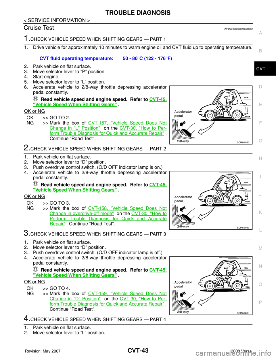
6. Accelerate vehicle to 2/8-way throttle depressing accelerator
pedal constantly.
Read vehicle speed and engine speed. Refer to CVT-45,
"Vehicle Speed When Shifting Gears" .
OK or NG
OK >> GO TO 2.
NG >> Mark the box of CVT-157, "
Vehicle Speed Does Not
Change in "L" Position" on the CVT-30, "How to Per-
form Trouble Diagnosis for Quick and Accurate Repair" .
Continue “Road Test”.
2.CHECK VEHICLE SPEED WHEN SHIFTING GEARS — PART 2
1. Park vehicle on flat surface.
2. Move selector lever to “D” position.
3. Push overdrive control switch. (O/D OFF indicator lamp is on.)
4. Accelerate vehicle to 2/8-way throttle depressing accelerator
pedal constantly.
Read vehicle speed and engine speed. Refer to CVT-45,
"Vehicle Speed When Shifting Gears" .
OK or NG
OK >> GO TO 3.
NG >> Mark the box of CVT-158, "
Vehicle Speed Does Not
Change in overdrive-off mode" on the CVT-30, "How to
Perform Trouble Diagnosis for Quick and Accurate
Repair" . Continue “Road Test”.
3.CHECK VEHICLE SPEED WHEN SHIFTING GEARS — PART 3
1. Park vehicle on flat surface.
2. Move selector lever to “D” position.
3. Push overdrive control switch. (O/D OFF indicator lamp is off.)
4. Accelerate vehicle to 2/8-way throttle depressing accelerator
pedal constantly.
Read vehicle speed and engine speed. Refer to CVT-45,
"Vehicle Speed When Shifting Gears" .
OK or NG
OK >> GO TO 4.
NG >> Mark the box of CVT-159, "
Vehicle Speed Does Not
Change in "D" Position" on the CVT-30, "How to Per-
form Trouble Diagnosis for Quick and Accurate Repair" .
Continue “Road Test”.
4.CHECK VEHICLE SPEED WHEN SHIFTING GEARS — PART 4
1. Park vehicle on flat surface.
2. Move selector lever to “L” position. CVT fluid operating temperature: 50 - 80°C (122 - 176°F)
SCIA6644E
SCIA6644E
SCIA6644E
Page 891 of 2771
CVT-52
< SERVICE INFORMATION >
TROUBLE DIAGNOSIS
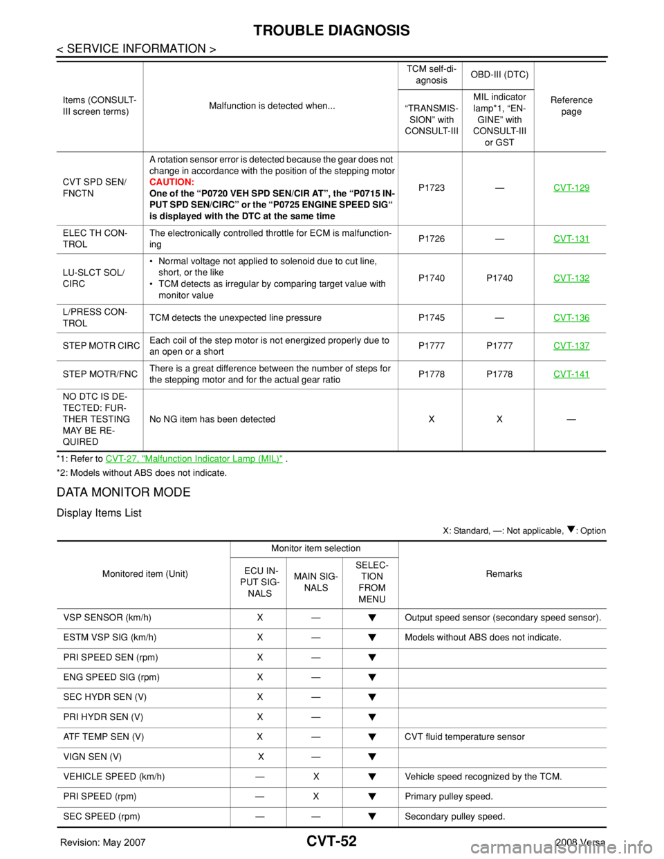
*1: Refer to CVT-27, "Malfunction Indicator Lamp (MIL)" .
*2: Models without ABS does not indicate.
DATA MONITOR MODE
Display Items List
X: Standard, —: Not applicable, : Option
CVT SPD SEN/
FNCTNA rotation sensor error is detected because the gear does not
change in accordance with the position of the stepping motor
CAUTION:
One of the “P0720 VEH SPD SEN/CIR AT”, the “P0715 IN-
PUT SPD SEN/CIRC” or the “P0725 ENGINE SPEED SIG“
is displayed with the DTC at the same timeP1723 —CVT-129
ELEC TH CON-
TROLThe electronically controlled throttle for ECM is malfunction-
ingP1726 —CVT-131
LU-SLCT SOL/
CIRC• Normal voltage not applied to solenoid due to cut line,
short, or the like
• TCM detects as irregular by comparing target value with
monitor valueP1740 P1740CVT-132
L/PRESS CON-
TROLTCM detects the unexpected line pressure P1745 —CVT-136
STEP MOTR CIRCEach coil of the step motor is not energized properly due to
an open or a shortP1777 P1777CVT-137
STEP MOTR/FNCThere is a great difference between the number of steps for
the stepping motor and for the actual gear ratioP1778 P1778CVT-141
NO DTC IS DE-
TECTED: FUR-
THER TESTING
MAY BE RE-
QUIREDNo NG item has been detected X X — Items (CONSULT-
III screen terms)Malfunction is detected when...TCM self-di-
agnosisOBD-III (DTC)
Reference
page “TRANSMIS-
SION” with
CONSULT-IIIMIL indicator
lamp*1, “EN-
GINE” with
CONSULT-III
or GST
Monitored item (Unit)Monitor item selection
Remarks ECU IN-
PUT SIG-
NALSMAIN SIG-
NALSSELEC-
TION
FROM
MENU
VSP SENSOR (km/h) X — Output speed sensor (secondary speed sensor).
ESTM VSP SIG (km/h) X — Models without ABS does not indicate.
PRI SPEED SEN (rpm) X —
ENG SPEED SIG (rpm) X —
SEC HYDR SEN (V) X —
PRI HYDR SEN (V) X —
ATF TEMP SEN (V) X — CVT fluid temperature sensor
VIGN SEN (V) X —
VEHICLE SPEED (km/h) — X Vehicle speed recognized by the TCM.
PRI SPEED (rpm) — X Primary pulley speed.
SEC SPEED (rpm) — — Secondary pulley speed.
Page 892 of 2771
TROUBLE DIAGNOSIS
CVT-53
< SERVICE INFORMATION >
D
E
F
G
H
I
J
K
L
MA
B
CVT
N
O
P
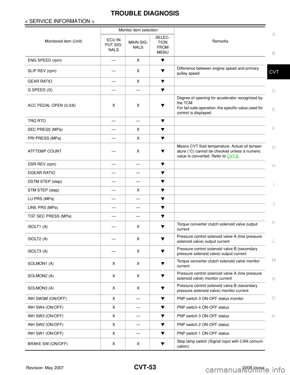
ENG SPEED (rpm) — X
SLIP REV (rpm) — XDifference between engine speed and primary
pulley speed
GEAR RATIO — X
G SPEED (G) — —
ACC PEDAL OPEN (0.0/8) X XDegree of opening for accelerator recognized by
the TCM
For fail-safe operation, the specific value used for
control is displayed.
TRQ RTO — —
SEC PRESS (MPa) — X
PRI PRESS (MPa) — X
ATFTEMP COUNT — XMeans CVT fluid temperature. Actual oil temper-
ature (°C) cannot be checked unless a numeric
value is converted. Refer to CVT-8
.
DSR REV (rpm) — —
DGEAR RATIO — —
DSTM STEP (step) — —
STM STEP (step) — X
LU PRS (MPa) — —
LINE PRS (MPa) — —
TGT SEC PRESS (MPa) — —
ISOLT1 (A) — XTorque converter clutch solenoid valve output
current
ISOLT2 (A) — XPressure control solenoid valve A (line pressure
solenoid valve) output current
ISOLT3 (A) — XPressure control solenoid valve B (secondary
pressure solenoid valve) output current
SOLMON1 (A) X XTorque converter clutch solenoid valve monitor
current
SOLMON2 (A) X XPressure control solenoid valve A (line pressure
solenoid valve) monitor current
SOLMON3 (A) X XPressure control solenoid valve B (secondary
pressure solenoid valve) monitor current
INH SW3M (ON/OFF) X — PNP switch 3 ON-OFF status monitor
INH SW4 (ON/OFF) X — PNP switch 4 ON-OFF status
INH SW3 (ON/OFF) X — PNP switch 3 ON-OFF status
INH SW2 (ON/OFF) X — PNP switch 2 ON-OFF status
INH SW1 (ON/OFF) X — PNP switch 1 ON-OFF status
BRAKE SW (ON/OFF) X XStop lamp switch (Signal input with CAN comuni-
cation) Monitored item (Unit)Monitor item selection
Remarks ECU IN-
PUT SIG-
NALSMAIN SIG-
NALSSELEC-
TION
FROM
MENU
Page 975 of 2771
CVT-136
< SERVICE INFORMATION >
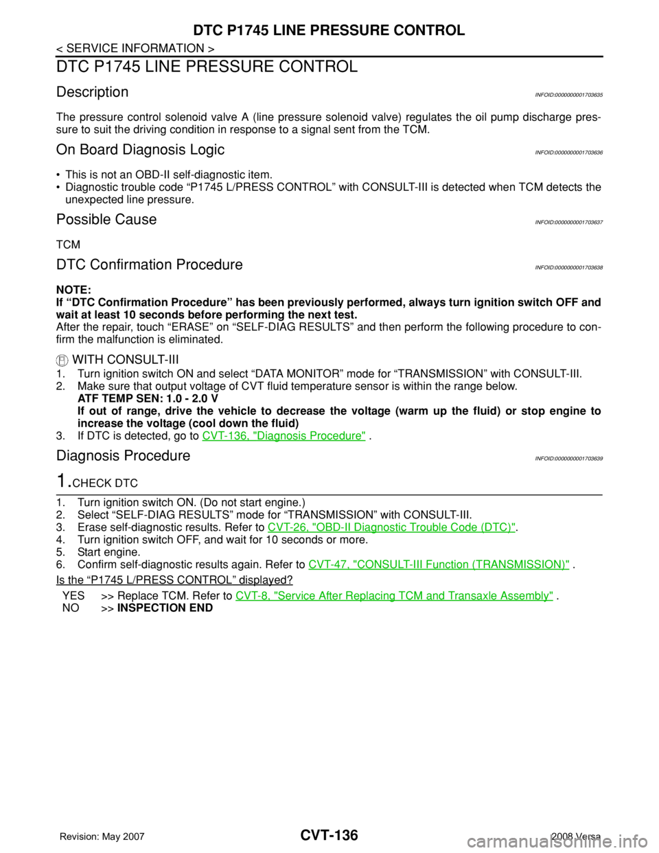
DTC P1745 LINE PRESSURE CONTROL
DTC P1745 LINE PRESSURE CONTROL
DescriptionINFOID:0000000001703635
The pressure control solenoid valve A (line pressure solenoid valve) regulates the oil pump discharge pres-
sure to suit the driving condition in response to a signal sent from the TCM.
On Board Diagnosis LogicINFOID:0000000001703636
• This is not an OBD-II self-diagnostic item.
• Diagnostic trouble code “P1745 L/PRESS CONTROL” with CONSULT-III is detected when TCM detects the
unexpected line pressure.
Possible CauseINFOID:0000000001703637
TCM
DTC Confirmation ProcedureINFOID:0000000001703638
NOTE:
If “DTC Confirmation Procedure” has been previously performed, always turn ignition switch OFF and
wait at least 10 seconds before performing the next test.
After the repair, touch “ERASE” on “SELF-DIAG RESULTS” and then perform the following procedure to con-
firm the malfunction is eliminated.
WITH CONSULT-III
1. Turn ignition switch ON and select “DATA MONITOR” mode for “TRANSMISSION” with CONSULT-III.
2. Make sure that output voltage of CVT fluid temperature sensor is within the range below.
ATF TEMP SEN: 1.0 - 2.0 V
If out of range, drive the vehicle to decrease the voltage (warm up the fluid) or stop engine to
increase the voltage (cool down the fluid)
3. If DTC is detected, go to CVT-136, "
Diagnosis Procedure" .
Diagnosis ProcedureINFOID:0000000001703639
1.CHECK DTC
1. Turn ignition switch ON. (Do not start engine.)
2. Select “SELF-DIAG RESULTS” mode for “TRANSMISSION” with CONSULT-III.
3. Erase self-diagnostic results. Refer to CVT-26, "
OBD-II Diagnostic Trouble Code (DTC)".
4. Turn ignition switch OFF, and wait for 10 seconds or more.
5. Start engine.
6. Confirm self-diagnostic results again. Refer to CVT-47, "
CONSULT-III Function (TRANSMISSION)" .
Is the
“P1745 L/PRESS CONTROL” displayed?
YES >> Replace TCM. Refer to CVT-8, "Service After Replacing TCM and Transaxle Assembly" .
NO >>INSPECTION END