2008 NISSAN LATIO timing belt
[x] Cancel search: timing beltPage 766 of 2771
BRC-1
BRAKES
C
D
E
G
H
I
J
K
L
M
SECTION BRC
A
B
BRC
N
O
P
CONTENTS
BRAKE CONTROL SYSTEM
ABS
SERVICE INFORMATION ............................
2
PRECAUTIONS ...................................................2
Precaution for Supplemental Restraint System
(SRS) "AIR BAG" and "SEAT BELT PRE-TEN-
SIONER" ...................................................................
2
Precaution for Brake System ....................................2
Precaution for Brake Control .....................................2
Precaution for CAN System ......................................3
PREPARATION ...................................................4
Special Service Tool .................................................4
Commercial Service Tool ..........................................4
SYSTEM DESCRIPTION .....................................5
System Component ...................................................5
ABS Function ............................................................5
EBD Function ............................................................5
Fail-Safe Function .....................................................5
Hydraulic Circuit Diagram .........................................6
CAN COMMUNICATION .....................................7
System Description ...................................................7
TROUBLE DIAGNOSIS ......................................8
How to Perform Trouble Diagnosis for Quick and
Accurate Repair ........................................................
8
Component Parts and Harness Connector Loca-
tion ..........................................................................
11
Schematic ...............................................................12
Wiring Diagram - ABS - ...........................................13
Basic Inspection ......................................................16
Warning Lamp and Indicator Timing ........................17
Control Unit Input/Output Signal Standard ..............17
CONSULT-III Function (ABS) ..................................18
TROUBLE DIAGNOSIS FOR SELF-DIAG-
NOSTIC ITEMS .................................................
24
Wheel Sensor System .............................................24
ABS Control Unit Inspection ....................................25
Solenoid Valve System Inspection ..........................25
Actuator Motor, Motor Relay, and Circuit Inspec-
tion ...........................................................................
26
ABS Control Unit Power and Ground Systems In-
spection ...................................................................
27
CAN Communication System Inspection .................28
TROUBLE DIAGNOSES FOR SYMPTOMS .....29
ABS Works Frequently ............................................29
Unexpected Pedal Action ........................................29
Long Stopping Distance ..........................................30
ABS Does Not Work ................................................30
Pedal Vibration or ABS Operation Noise .................30
WHEEL SENSORS ...........................................32
Removal and Installation .........................................32
SENSOR ROTOR ..............................................34
Removal and Installation .........................................34
ACTUATOR AND ELECTRIC UNIT (ASSEM-
BLY) ..................................................................
35
Removal and Installation .........................................35
Page 1075 of 2771
EC-1
ENGINE
C
D
E
F
G
H
I
J
K
L
M
SECTION EC
A
EC
N
O
P
CONTENTS
ENGINE CONTROL SYSTEM
SERVICE INFORMATION ............................9
INDEX FOR DTC .................................................9
DTC No. Index ..........................................................9
Alphabetical Index ...................................................12
PRECAUTIONS ..................................................16
Precaution for Supplemental Restraint System
(SRS) "AIR BAG" and "SEAT BELT PRE-TEN-
SIONER" .................................................................
16
Precaution for Procedure without Cowl Top Cover ....16
On Board Diagnosis (OBD) System of Engine and
A/T, CVT .................................................................
16
Precaution ...............................................................17
PREPARATION ..................................................20
Special Service Tool ...............................................20
Commercial Service Tool ........................................21
ENGINE CONTROL SYSTEM ............................22
Schematic ...............................................................22
Multiport Fuel Injection (MFI) System .....................22
Electronic Ignition (EI) System ................................25
Fuel Cut Control (at No Load and High Engine
Speed) .....................................................................
25
AIR CONDITIONING CUT CONTROL ...............27
Input/Output Signal Chart ........................................27
System Description .................................................27
AUTOMATIC SPEED CONTROL DEVICE
(ASCD) ...............................................................
28
System Description .................................................28
Component Description ...........................................29
CAN COMMUNICATION ....................................30
System Description .................................................30
EVAPORATIVE EMISSION SYSTEM ................31
Description ..............................................................31
Component Inspection ............................................33
Removal and Installation .........................................35
How to Detect Fuel Vapor Leakage .........................35
ON BOARD REFUELING VAPOR RECOV-
ERY (ORVR) ......................................................
38
System Description ..................................................38
Diagnosis Procedure ...............................................38
Component Inspection .............................................40
POSITIVE CRANKCASE VENTILATION .........43
Description ...............................................................43
Component Inspection .............................................43
NVIS (NISSAN VEHICLE IMMOBILIZER SYS-
TEM-NATS) .......................................................
45
Description ...............................................................45
ON BOARD DIAGNOSTIC (OBD) SYSTEM ....46
Introduction ..............................................................46
Two Trip Detection Logic .........................................46
Emission-related Diagnostic Information .................47
Malfunction Indicator Lamp (MIL) ............................60
OBD System Operation Chart .................................63
BASIC SERVICE PROCEDURE .......................69
Basic Inspection ......................................................69
Idle Speed and Ignition Timing Check .....................73
Procedure After Replacing ECM .............................75
VIN Registration ......................................................75
Accelerator Pedal Released Position Learning .......76
Throttle Valve Closed Position Learning .................76
Idle Air Volume Learning .........................................76
Fuel Pressure Check ...............................................78
TROUBLE DIAGNOSIS ....................................81
Trouble Diagnosis Introduction ................................81
DTC Inspection Priority Chart ..................................86
Fail-Safe Chart ........................................................87
Symptom Matrix Chart .............................................88
Engine Control Component Parts Location .............93
Vacuum Hose Drawing ............................................99
Circuit Diagram ......................................................100
ECM Harness Connector Terminal Layout ............102
Page 1678 of 2771
EM-1
ENGINE
C
D
E
F
G
H
I
J
K
L
M
SECTION EM
A
EM
N
O
P
CONTENTS
ENGINE MECHANICAL
SERVICE INFORMATION ............................3
PRECAUTIONS ...................................................3
Precaution for Supplemental Restraint System
(SRS) "AIR BAG" and "SEAT BELT PRE-TEN-
SIONER" ...................................................................
3
Precaution for Procedure without Cowl Top Cover ......3
Precaution Necessary for Steering Wheel Rota-
tion After Battery Disconnect .....................................
3
Precaution for Drain Coolant .....................................4
Precaution for Disconnecting Fuel Piping .................4
Precaution for Removal and Disassembly ................4
Precaution for Inspection, Repair and Replace-
ment ..........................................................................
4
Precaution for Assembly and Installation ..................4
Parts Requiring Angular Tightening ..........................4
Precaution for Liquid Gasket .....................................5
PREPARATION ...................................................7
Special Service Tool .................................................7
Commercial Service Tool ..........................................9
NOISE, VIBRATION AND HARSHNESS
(NVH) TROUBLESHOOTING ............................
11
NVH Troubleshooting - Engine Noise .....................11
Use the Chart Below to Help You Find the Cause
of the Symptom .......................................................
12
DRIVE BELTS ....................................................13
Component ..............................................................13
Checking Drive Belts ...............................................13
Tension Adjustment ................................................13
Removal and Installation .........................................13
Component ..............................................................14
Removal and Installation of Drive Belt Auto Ten-
sioner ......................................................................
14
AIR CLEANER AND AIR DUCT ........................16
Component ..............................................................16
Removal and Installation .........................................16
Changing Air Cleaner Filter .....................................17
INTAKE MANIFOLD .........................................18
Component ..............................................................18
Removal and Installation .........................................18
EXHAUST MANIFOLD ......................................21
Component ..............................................................21
Removal and Installation .........................................21
OIL PAN ............................................................24
Component ..............................................................24
Removal and Installation .........................................24
IGNITION COIL, SPARK PLUG AND ROCK-
ER COVER ........................................................
30
Component ..............................................................30
Removal and Installation .........................................30
FUEL INJECTOR AND FUEL TUBE ................33
Component ..............................................................33
Removal and Installation .........................................33
TIMING CHAIN ..................................................37
Component ..............................................................37
Removal and Installation .........................................38
CAMSHAFT .......................................................47
Component ..............................................................47
Removal and Installation .........................................47
Valve Clearance ......................................................55
OIL SEAL ..........................................................59
Removal and Installation of Valve Oil Seal ..............59
Removal and Installation of Front Oil Seal ..............59
Removal and Installation of Rear Oil Seal ...............60
CYLINDER HEAD .............................................62
On-Vehicle Service ..................................................62
Component ..............................................................63
Removal and Installation .........................................63
Component ..............................................................65
Disassembly and Assembly .....................................66
Inspection After Disassembly ..................................67
Page 1688 of 2771
NOISE, VIBRATION AND HARSHNESS (NVH) TROUBLESHOOTING
EM-11
< SERVICE INFORMATION >
C
D
E
F
G
H
I
J
K
L
MA
EM
N
P O
NOISE, VIBRATION AND HARSHNESS (NVH) TROUBLESHOOTING
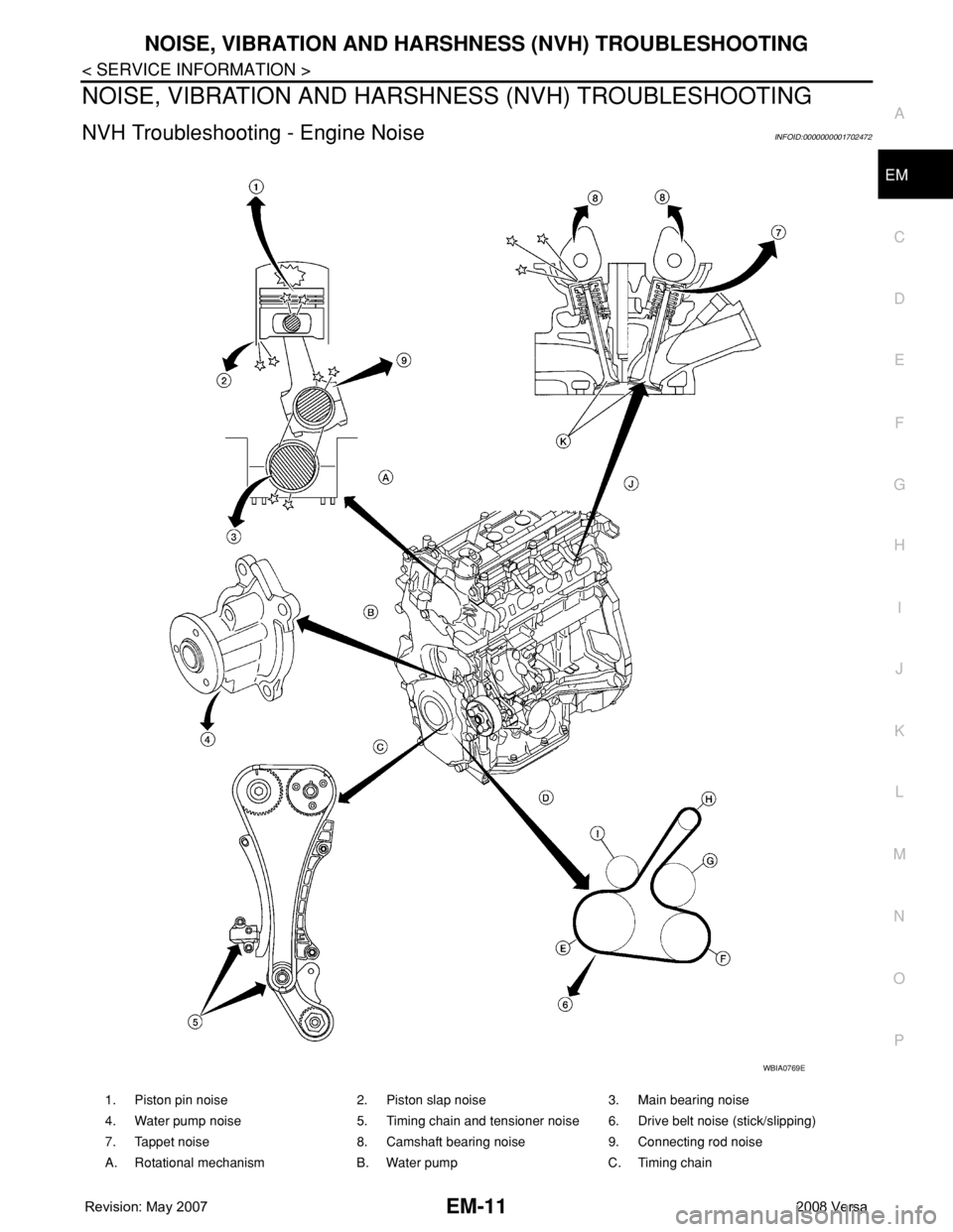
NVH Troubleshooting - Engine NoiseINFOID:0000000001702472
WBIA0769E
1. Piston pin noise 2. Piston slap noise 3. Main bearing noise
4. Water pump noise 5. Timing chain and tensioner noise 6. Drive belt noise (stick/slipping)
7. Tappet noise 8. Camshaft bearing noise 9. Connecting rod noise
A. Rotational mechanism B. Water pump C. Timing chain
Page 1689 of 2771
EM-12
< SERVICE INFORMATION >
NOISE, VIBRATION AND HARSHNESS (NVH) TROUBLESHOOTING
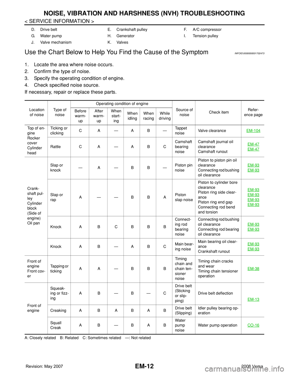
Use the Chart Below to Help You Find the Cause of the Symptom
INFOID:0000000001702473
1. Locate the area where noise occurs.
2. Confirm the type of noise.
3. Specify the operating condition of engine.
4. Check specified noise source.
If necessary, repair or replace these parts.
A: Closely related B: Related C: Sometimes related —: Not relatedD. Drive belt E. Crankshaft pulley F. A/C compressor
G. Water pump H. Generator I. Tension pulley
J. Valve mechanism K. Valves
Location
of noiseTyp e of
noiseOperating condition of engine
Source of
noiseCheck itemRefer-
ence page Before
warm-
upAfter
warm-
upWhen
start-
ingWhen
idlingWhen
racingWhile
driving
Top of en-
gine
Rocker
cover
Cylinder
headTicking or
clickingCA—AB—Tappet
noiseValve clearanceEM-104
Rattle C A — A B CCamshaft
bearing
noiseCamshaft journal oil
clearance
Camshaft runoutEM-47EM-47
Crank-
shaft pul-
ley
Cylinder
block
(Side of
engine)
Oil panSlap or
knock—A—BB—Piston pin
noisePiston to piston pin oil
clearance
Connecting rod bushing
oil clearanceEM-93
EM-93
Slap or
rapA——BBAPiston
slap noisePiston to cylinder bore
clearance
Piston ring side clear-
ance
Piston ring end gap
Connecting rod bend
and torsionEM-93EM-93
EM-93
EM-93
Knock A B C B B BConnect-
ing rod
bearing
noiseConnecting rod bushing
oil clearance
Connecting rod bearing
oil clearanceEM-93EM-93
Knock A B — A B CMain bear-
ing noiseMain bearing oil clear-
ance
Crankshaft runoutEM-93EM-93
Front of
engine
Front cov-
erTapping or
tickingAA—BBBTiming
chain and
chain ten-
sioner
noiseTiming chain cracks
and wear
Timing chain tensioner
operationEM-38
Front of
engineSqueak-
ing or fizz-
ingAB—B—CDrive belt
(Sticking
or slip-
ping)Drive belt deflection
EM-13
Creaking A B A B A BDrive belt
(Slipping)Idler pulley bearing op-
eration
Squall
CreakAB—BABWater
pump
noiseWater pump operationCO-16
Page 1714 of 2771
TIMING CHAIN
EM-37
< SERVICE INFORMATION >
C
D
E
F
G
H
I
J
K
L
MA
EM
N
P O
TIMING CHAIN
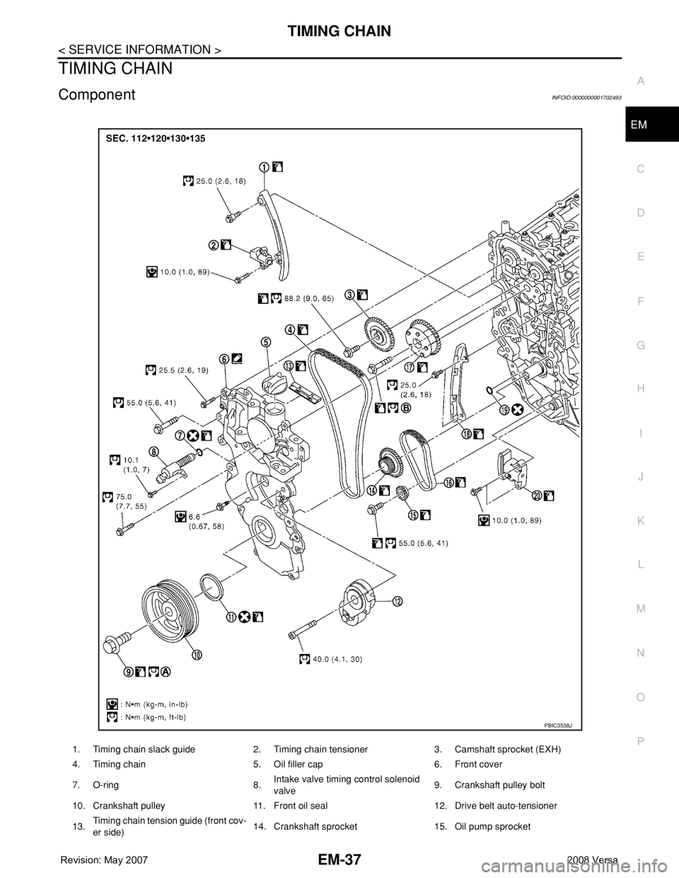
ComponentINFOID:0000000001702493
1. Timing chain slack guide 2. Timing chain tensioner 3. Camshaft sprocket (EXH)
4. Timing chain 5. Oil filler cap 6. Front cover
7. O-ring 8.Intake valve timing control solenoid
valve9. Crankshaft pulley bolt
10. Crankshaft pulley 11. Front oil seal 12. Drive belt auto-tensioner
13.Timing chain tension guide (front cov-
er side)14. Crankshaft sprocket 15. Oil pump sprocket
PBIC3538J
Page 1715 of 2771
EM-38
< SERVICE INFORMATION >
TIMING CHAIN
Removal and Installation
INFOID:0000000001844926
CAUTION:
The rotating direction indicated in the text indicates all directions seen from the engine front.
REMOVAL
1. Remove front RH wheel. Refer to WT-6, "Rotation".
2. Remove front fender protector (RH). Refer to EI-23, "
Removal and Installation".
3. Drain engine oil. Refer to LU-7, "
Changing Engine Oil".
NOTE:
Perform this step when engine is cold.
4. Remove the following parts.
• Rocker cover: Refer to EM-30, "
Component".
• Drive belt: Refer to EM-13, "
Removal and Installation".
• Water pump pulley: Refer to CO-16, "
Component".
• Ground cable (between engine bracket (RH) and radiator core support)
5. Support the bottom surface of engine using a transmission jack, and then remove the engine bracket and
insulator (RH). Refer to EM-72, "
Component".
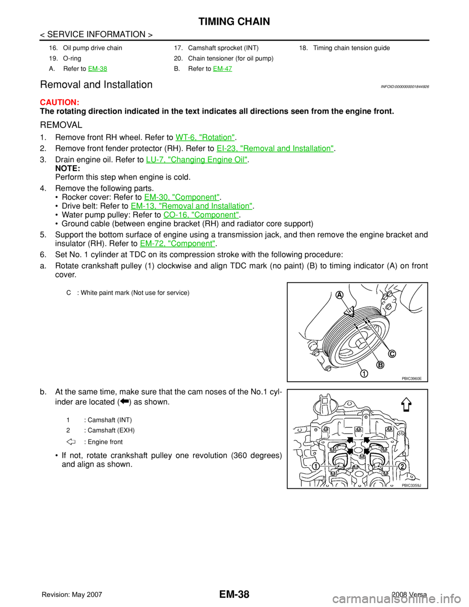
6. Set No. 1 cylinder at TDC on its compression stroke with the following procedure:
a. Rotate crankshaft pulley (1) clockwise and align TDC mark (no paint) (B) to timing indicator (A) on front
cover.
b. At the same time, make sure that the cam noses of the No.1 cyl-
inder are located ( ) as shown.
• If not, rotate crankshaft pulley one revolution (360 degrees)
and align as shown.
16. Oil pump drive chain 17. Camshaft sprocket (INT) 18. Timing chain tension guide
19. O-ring 20. Chain tensioner (for oil pump)
A. Refer to EM-38
B. Refer to EM-47
C : White paint mark (Not use for service)
PBIC3960E
1 : Camshaft (INT)
2 : Camshaft (EXH)
: Engine front
PBIC3359J
Page 1716 of 2771
TIMING CHAIN
EM-39
< SERVICE INFORMATION >
C
D
E
F
G
H
I
J
K
L
MA
EM
N
P O
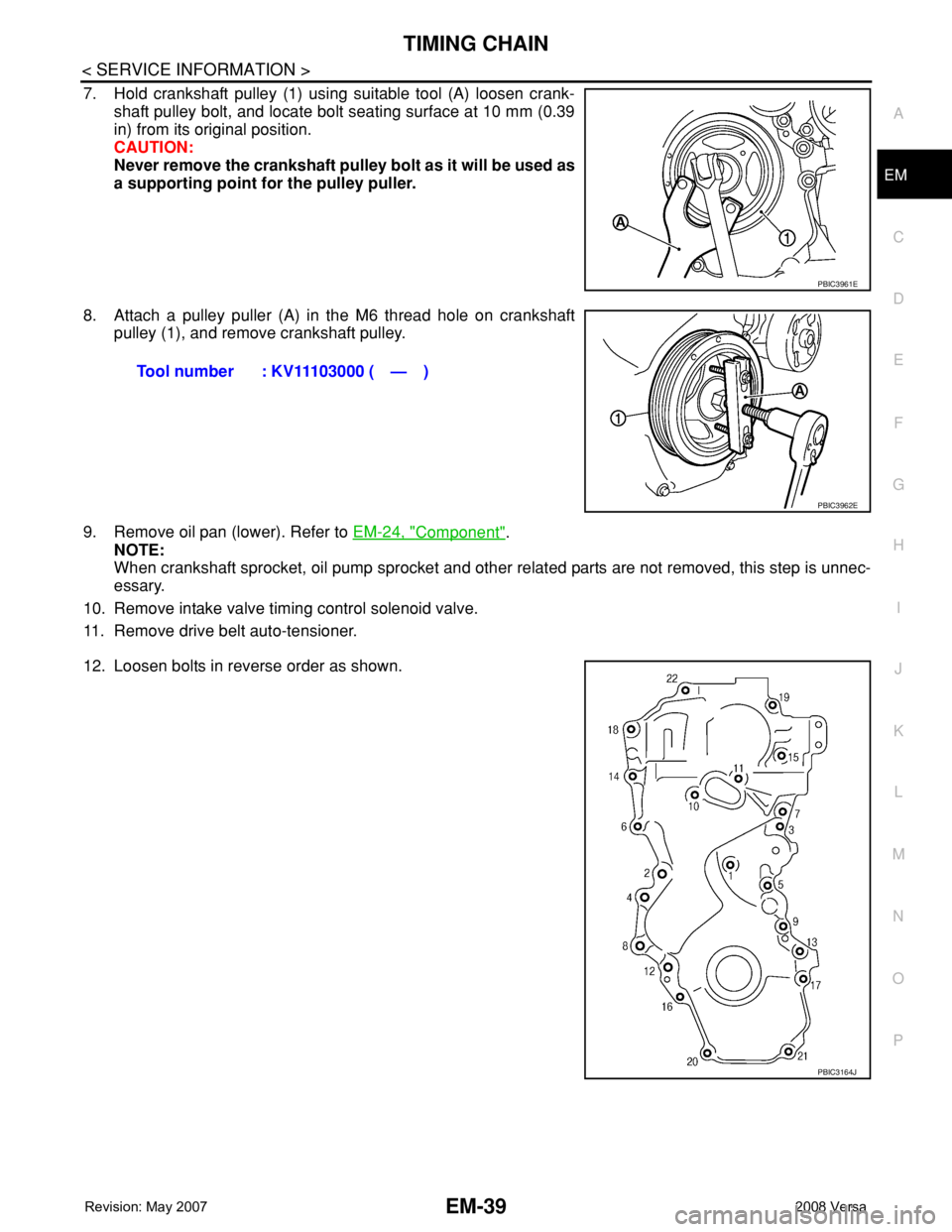
7. Hold crankshaft pulley (1) using suitable tool (A) loosen crank-
shaft pulley bolt, and locate bolt seating surface at 10 mm (0.39
in) from its original position.
CAUTION:
Never remove the crankshaft pulley bolt as it will be used as
a supporting point for the pulley puller.
8. Attach a pulley puller (A) in the M6 thread hole on crankshaft
pulley (1), and remove crankshaft pulley.
9. Remove oil pan (lower). Refer to EM-24, "
Component".
NOTE:
When crankshaft sprocket, oil pump sprocket and other related parts are not removed, this step is unnec-
essary.
10. Remove intake valve timing control solenoid valve.
11. Remove drive belt auto-tensioner.
12. Loosen bolts in reverse order as shown.
PBIC3961E
Tool number : KV11103000 ( — )
PBIC3962E
PBIC3164J