Page 2478 of 2771

HARNESS
PG-45
< SERVICE INFORMATION >
C
D
E
F
G
H
I
J
L
MA
B
PG
N
O
P
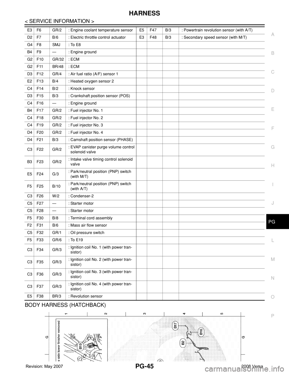
BODY HARNESS (HATCHBACK)
E3 F6 GR/2 : Engine coolant temperature sensor E5 F47 B/3 : Powertrain revolution sensor (with A/T)
D2 F7 B/6 : Electric throttle control actuatorE3 F48 B/3 : Secondary speed sensor (with M/T)
G4 F8 SMJ : To E8
B4 F9 — : Engine ground
G2 F10 GR/32 : ECM
G2 F11 BR/48 : ECM
D3 F12 GR/4 : Air fuel ratio (A/F) sensor 1
E2 F13 B/4 : Heated oxygen sensor 2
C4 F14 B/2 : Knock sensor
D3 F15 B/3 : Crankshaft position sensor (POS)
C4 F16 — : Engine ground
B4 F17 GR/2 : Fuel injector No. 1
C4 F18 GR/2 : Fuel injector No. 2
C4 F19 GR/2 : Fuel injector No. 3
D4 F20 GR/2 : Fuel injector No. 4
D4 F21 B/3 : Camshaft position sensor (PHASE)
C3 F22 GR/2: EVAP canister purge volume control
solenoid valve
B3 F23 GR/2: Intake valve timing control solenoid
valve
E5 F24 G/3: Park/neutral position (PNP) switch
(with M/T)
F5 F25 B/10: Park/neutral position (PNP) switch
(with A/T)
C3 F26 W/2 : Condenser-2
C5 F27 — : Starter motor
C5 F28 — : Starter motor
F5 F30 B/8 : Terminal cord assembly
F2 F31 B/6 : Mass air flow sensor
C5 F32 GR/1 : Oil pressure switch
F5 F33 GR/6 : To E19
C3 F34 GR/3: Ignition coil No. 1 (with power tran-
sistor)
C3 F35 GR/3: Ignition coil No. 2 (with power tran-
sistor)
C3 F36 GR/3: Ignition coil No. 3 (with power tran-
sistor)
C3 F37 GR/3: Ignition coil No. 4 (with power tran-
sistor)
E5 F38 BR/3 : Revolution sensor
Page 2667 of 2771

DRIVER AIR BAG MODULE
SRS-33
< ON-VEHICLE REPAIR >
C
D
E
F
G
I
J
K
L
MA
B
SRS
N
O
P
ON-VEHICLE REPAIR
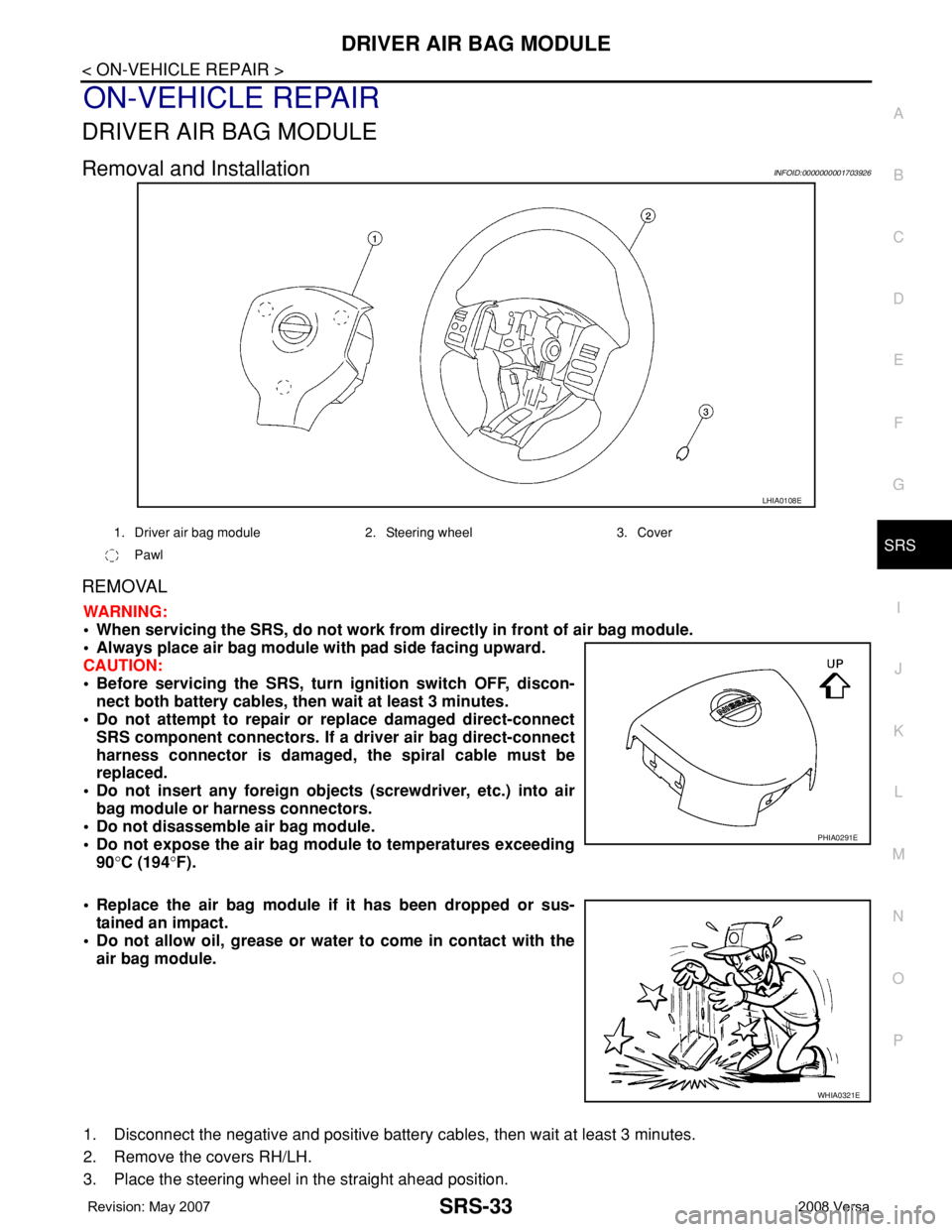
DRIVER AIR BAG MODULE
Removal and InstallationINFOID:0000000001703926
REMOVAL
WARNING:
• When servicing the SRS, do not work from directly in front of air bag module.
• Always place air bag module with pad side facing upward.
CAUTION:
• Before servicing the SRS, turn ignition switch OFF, discon-
nect both battery cables, then wait at least 3 minutes.
• Do not attempt to repair or replace damaged direct-connect
SRS component connectors. If a driver air bag direct-connect
harness connector is damaged, the spiral cable must be
replaced.
• Do not insert any foreign objects (screwdriver, etc.) into air
bag module or harness connectors.
• Do not disassemble air bag module.
• Do not expose the air bag module to temperatures exceeding
90°C (194°F).
• Replace the air bag module if it has been dropped or sus-
tained an impact.
• Do not allow oil, grease or water to come in contact with the
air bag module.
1. Disconnect the negative and positive battery cables, then wait at least 3 minutes.
2. Remove the covers RH/LH.
3. Place the steering wheel in the straight ahead position.
LHIA0108E
1. Driver air bag module 2. Steering wheel 3. Cover
Pawl
PHIA0291E
WHIA0321E
Page 2672 of 2771

SRS-38
< ON-VEHICLE REPAIR >
FRONT PASSENGER AIR BAG MODULE
FRONT PASSENGER AIR BAG MODULE
Removal and InstallationINFOID:0000000001703928
REMOVAL
WARNING:
• When servicing the SRS, do not work from directly in front of air bag module.
• Always place front passenger air bag module with pad side facing upward.
CAUTION:
• Before servicing SRS, turn the ignition switch OFF, disconnect both battery cables and wait at least
3 minutes.
• Do not use old bolts after removal; replace with new bolts.
• Do not insert any foreign objects (screwdriver, etc.) into air bag module or harness connectors.
• Do not disassemble air bag module.
• Do not expose the front passenger air bag module to temperatures exceeding 90°C (194°F).
• Replace the front passenger air bag module if it has been
dropped or sustained an impact.
• Do not allow oil, grease or water to come in contact with the
front passenger air bag module.
1. Disconnect the negative and positive battery cables, then wait at least 3 minutes.
2. Remove the side ventilator assembly (right). Refer to IP-10
.
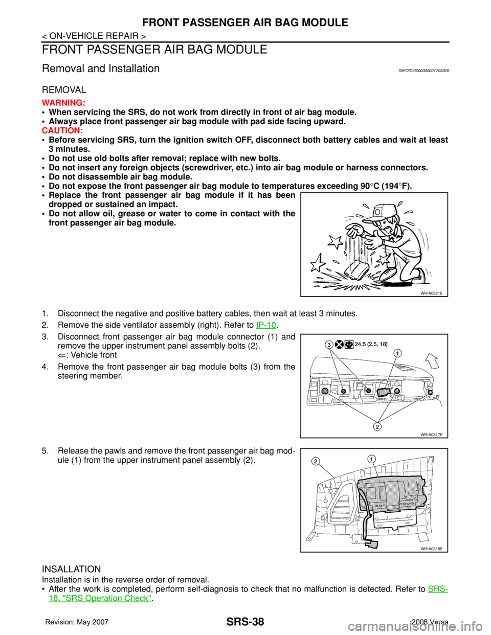
3. Disconnect front passenger air bag module connector (1) and
remove the upper instrument panel assembly bolts (2).
⇐: Vehicle front
4. Remove the front passenger air bag module bolts (3) from the
steering member.
5. Release the pawls and remove the front passenger air bag mod-
ule (1) from the upper instrument panel assembly (2).
INSALLATION
Installation is in the reverse order of removal.
• After the work is completed, perform self-diagnosis to check that no malfunction is detected. Refer to SRS-
18, "SRS Operation Check".
WHIA0321E
WHIA0317E
WHIA0318E
Page 2674 of 2771

SRS-40
< ON-VEHICLE REPAIR >
SIDE CURTAIN AIR BAG MODULE
• When servicing the SRS, do not work from directly in front of air bag module.
• Always place the curtain air bag module with deployment side facing upward.
• Do not reuse center pillar upper garnish if removed.
CAUTION:
• Before servicing SRS, turn the ignition switch OFF, disconnect both battery cables and wait at least
3 minutes.
• Do not use old bolts after removal; replace with new bolts.
• Do not insert any foreign objects (screwdriver, etc.) into air bag module or harness connectors.
• Do not disassemble air bag module.
• Do not expose the side curtain air bag module to temperatures exceeding 90°C (194°F).
• Replace the side curtain air bag module if it has been dropped
or sustained an impact.
• Do not allow oil, grease or water to come in contact with the
side curtain air bag module.
• Do not attempt to repair or replace damaged direct-connect
SRS component connectors. If a direct-connect harness con-
nector is damaged, the harness must be replaced.
1. Disconnect both the negative and positive battery cables, then wait at least 3 minutes.
2. Remove the headlining. Refer to EI-45
.
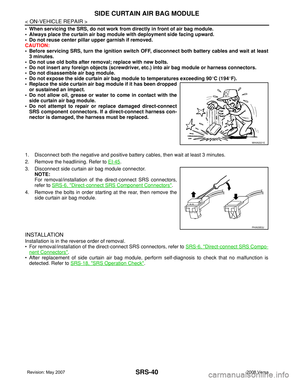
3. Disconnect side curtain air bag module connector.
NOTE:
For removal/installation of the direct-connect SRS connectors,
refer to SRS-6, "
Direct-connect SRS Component Connectors".
4. Remove the bolts in order starting at the rear, then remove the
side curtain air bag module.
INSTALLATION
Installation is in the reverse order of removal.
• For removal/installation of the direct-connect SRS connectors, refer to SRS-6, "
Direct-connect SRS Compo-
nent Connectors".
• After replacement of side curtain air bag module, perform self-diagnosis to check that no malfunction is
detected. Refer to SRS-18, "
SRS Operation Check".
WHIA0321E
PHIA0953J