2008 NISSAN LATIO oil temperature
[x] Cancel search: oil temperaturePage 2266 of 2771

MA-6
< SERVICE INFORMATION >
PERIODIC MAINTENANCE
PERIODIC MAINTENANCE
Introduction of Periodic MaintenanceINFOID:0000000001704722
Two different maintenance schedules are provided, and should be used, depending upon the conditions in
which the vehicle is mainly operated. After 60,000 miles (96,000 km) or 48 months, continue the periodic
maintenance at the same mileage/time intervals.
Schedule 1INFOID:0000000001704723
Emission Control System Maintenance
Abbreviations: R = Replace. I = Inspect. Correct or replace if necessary. [ ]: At the mileage intervals only
Schedule 1Follow Periodic Maintenance Schedule 1 if your driving habits frequently includes
one or more of the following driving conditions:
• Repeated short trips of less than 5 miles (8 km).
• Repeated short trips of less than 10 miles (16 km) with outside temperatures re-
maining below freezing.
• Operating in hot weather in stop-and-go “rush hour” traffic.
• Extensive idling and/or low speed driving for long distances, such as police, taxi
or door-to-door delivery use.
• Driving in dusty conditions.
• Driving on rough, muddy, or salt spread roads.
• Towing a trailer, using a camper or a car-top carrier.Emission Control Sys-
tem MaintenanceMA-6
Chassis and Body
Maintenance
MA-6
Schedule 2Follow Periodic Maintenance Schedule 2 if none of the driving conditions shown
in Schedule 1 apply to your driving habits.Emission Control Sys-
tem MaintenanceMA-8Chassis and Body
MaintenanceMA-8
MAINTENANCE OPERATIONMAINTENANCE INTERVAL
Reference Section -
Page or - Content Title Perform at number of
miles, kilometers or
months, whichever
comes first.Miles x 1,000
(km x 1,000)
Months3.75
(6)
37.5
(12)
611 . 2 5
(18)
915
(24)
1218.75
(30)
1522.5
(36)
1826.25
(42)
2130
(48)
24
Drive belt NOTE (1)MA-12
Air cleaner filter NOTE (2) [R]MA-14
EVAP vapor linesI*MA-18
Fuel linesI*MA-14
Fuel filter NOTE (3)—
Engine coolant NOTE (4)MA-12
Engine oil R R R R R R R RMA-15
Engine oil filter (Use
genuine oil filter or
equivalent)RRRRRRRRMA-16
Spark plugs (Iridium/
platinum-tipped type)Replace every 105,000 miles (169,000 km)MA-17
Intake and exhaust
valve clearance NOTE (5)EM-104, "Standard
and Limit"
Page 2276 of 2771
MA-16
< SERVICE INFORMATION >
ENGINE MAINTENANCE
1. Warm up engine, park vehicle on a level surface and check for engine oil leakage from engine compo-
nents. Refer to LU-6, "
Inspection" .
2. Stop engine and wait for 10 minutes.
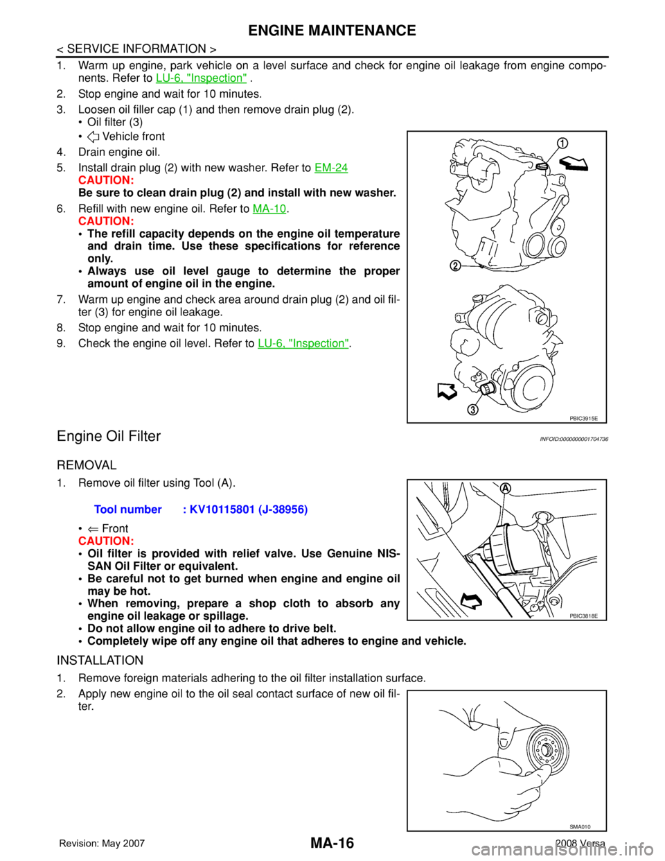
3. Loosen oil filler cap (1) and then remove drain plug (2).
• Oil filter (3)
• Vehicle front
4. Drain engine oil.
5. Install drain plug (2) with new washer. Refer to EM-24
CAUTION:
Be sure to clean drain plug (2) and install with new washer.
6. Refill with new engine oil. Refer to MA-10
.
CAUTION:
• The refill capacity depends on the engine oil temperature
and drain time. Use these specifications for reference
only.
• Always use oil level gauge to determine the proper
amount of engine oil in the engine.
7. Warm up engine and check area around drain plug (2) and oil fil-
ter (3) for engine oil leakage.
8. Stop engine and wait for 10 minutes.
9. Check the engine oil level. Refer to LU-6, "
Inspection".
Engine Oil FilterINFOID:0000000001704736
REMOVAL
1. Remove oil filter using Tool (A).
•⇐ Front
CAUTION:
• Oil filter is provided with relief valve. Use Genuine NIS-
SAN Oil Filter or equivalent.
• Be careful not to get burned when engine and engine oil
may be hot.
• When removing, prepare a shop cloth to absorb any
engine oil leakage or spillage.
• Do not allow engine oil to adhere to drive belt.
• Completely wipe off any engine oil that adheres to engine and vehicle.
INSTALLATION
1. Remove foreign materials adhering to the oil filter installation surface.
2. Apply new engine oil to the oil seal contact surface of new oil fil-
ter.
PBIC3915E
Tool number : KV10115801 (J-38956)
PBIC3818E
SMA010
Page 2282 of 2771
MA-22
< SERVICE INFORMATION >
CHASSIS AND BODY MAINTENANCE
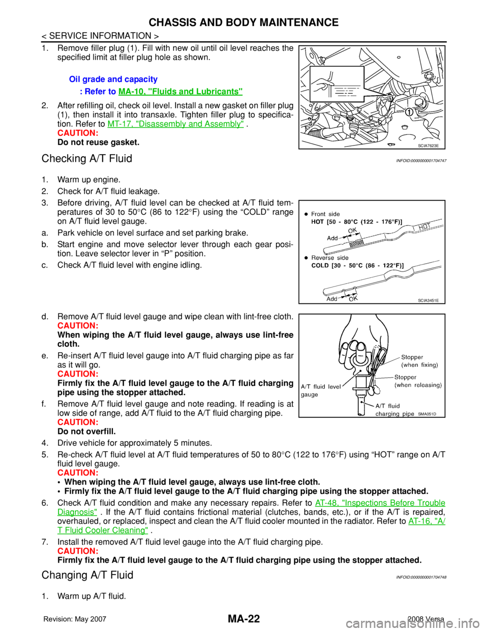
1. Remove filler plug (1). Fill with new oil until oil level reaches the
specified limit at filler plug hole as shown.
2. After refilling oil, check oil level. Install a new gasket on filler plug
(1), then install it into transaxle. Tighten filler plug to specifica-
tion. Refer to MT-17, "
Disassembly and Assembly" .
CAUTION:
Do not reuse gasket.
Checking A/T FluidINFOID:0000000001704747
1. Warm up engine.
2. Check for A/T fluid leakage.
3. Before driving, A/T fluid level can be checked at A/T fluid tem-
peratures of 30 to 50°C (86 to 122°F) using the “COLD” range
on A/T fluid level gauge.
a. Park vehicle on level surface and set parking brake.
b. Start engine and move selector lever through each gear posi-
tion. Leave selector lever in “P” position.
c. Check A/T fluid level with engine idling.
d. Remove A/T fluid level gauge and wipe clean with lint-free cloth.
CAUTION:
When wiping the A/T fluid level gauge, always use lint-free
cloth.
e. Re-insert A/T fluid level gauge into A/T fluid charging pipe as far
as it will go.
CAUTION:
Firmly fix the A/T fluid level gauge to the A/T fluid charging
pipe using the stopper attached.
f. Remove A/T fluid level gauge and note reading. If reading is at
low side of range, add A/T fluid to the A/T fluid charging pipe.
CAUTION:
Do not overfill.
4. Drive vehicle for approximately 5 minutes.
5. Re-check A/T fluid level at A/T fluid temperatures of 50 to 80°C (122 to 176°F) using “HOT” range on A/T
fluid level gauge.
CAUTION:
• When wiping the A/T fluid level gauge, always use lint-free cloth.
• Firmly fix the A/T fluid level gauge to the A/T fluid charging pipe using the stopper attached.
6. Check A/T fluid condition and make any necessary repairs. Refer to AT-48, "
Inspections Before Trouble
Diagnosis" . If the A/T fluid contains frictional material (clutches, bands, etc.), or if the A/T is repaired,
overhauled, or replaced, inspect and clean the A/T fluid cooler mounted in the radiator. Refer to AT-16, "
A/
T Fluid Cooler Cleaning" .
7. Install the removed A/T fluid level gauge into the A/T fluid charging pipe.
CAUTION:
Firmly fix the A/T fluid level gauge to the A/T fluid charging pipe using the stopper attached.
Changing A/T FluidINFOID:0000000001704748
1. Warm up A/T fluid.Oil grade and capacity
: Refer to MA-10, "
Fluids and Lubricants"
SCIA7623E
SCIA3451E
SMA051D
Page 2345 of 2771
PRECAUTIONS
MTC-7
< SERVICE INFORMATION >
C
D
E
F
G
H
I
K
L
MA
B
MTC
N
O
P
• Allow components stored in cool areas to warm to working area temperature before removing seal
caps. This prevents condensation from forming inside A/C components.
• Thoroughly remove moisture from the refrigeration system before charging the refrigerant.
• Always replace used O-rings.
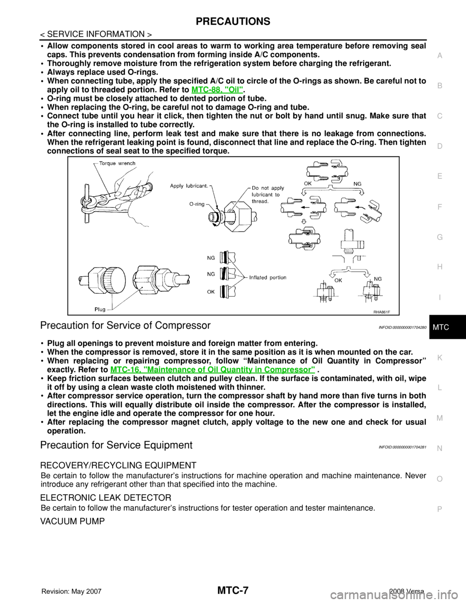
• When connecting tube, apply the specified A/C oil to circle of the O-rings as shown. Be careful not to
apply oil to threaded portion. Refer to MTC-88, "
Oil".
• O-ring must be closely attached to dented portion of tube.
• When replacing the O-ring, be careful not to damage O-ring and tube.
• Connect tube until you hear it click, then tighten the nut or bolt by hand until snug. Make sure that
the O-ring is installed to tube correctly.
• After connecting line, perform leak test and make sure that there is no leakage from connections.
When the refrigerant leaking point is found, disconnect that line and replace the O-ring. Then tighten
connections of seal seat to the specified torque.
Precaution for Service of CompressorINFOID:0000000001704280
•Plug all openings to prevent moisture and foreign matter from entering.
•When the compressor is removed, store it in the same position as it is when mounted on the car.
•When replacing or repairing compressor, follow “Maintenance of Oil Quantity in Compressor”
exactly. Refer to MTC-16, "
Maintenance of Oil Quantity in Compressor" .
•Keep friction surfaces between clutch and pulley clean. If the surface is contaminated, with oil, wipe
it off by using a clean waste cloth moistened with thinner.
•After compressor service operation, turn the compressor shaft by hand more than five turns in both
directions. This will equally distribute oil inside the compressor. After the compressor is installed,
let the engine idle and operate the compressor for one hour.
•After replacing the compressor magnet clutch, apply voltage to the new one and check for usual
operation.
Precaution for Service EquipmentINFOID:0000000001704281
RECOVERY/RECYCLING EQUIPMENT
Be certain to follow the manufacturer’s instructions for machine operation and machine maintenance. Never
introduce any refrigerant other than that specified into the machine.
ELECTRONIC LEAK DETECTOR
Be certain to follow the manufacturer’s instructions for tester operation and tester maintenance.
VACUUM PUMP
RHA861F
Page 2354 of 2771
MTC-16
< SERVICE INFORMATION >
OIL
OIL
Maintenance of Oil Quantity in CompressorINFOID:0000000001704289
The oil in the compressor circulates through the system with the refrigerant. Add oil to compressor when
replacing any component or after a large refrigerant leakage occurred. It is important to maintain the specified
amount.
If oil quantity is not maintained properly, the following malfunctions may result:
• Lack of oil: May lead to a seized compressor.
• Excessive oil: Inadequate cooling (thermal exchange interference)
OIL
OIL RETURN OPERATION
Adjust the oil quantity according to the test group shown below.
1.CHECK OIL RETURN OPERATION
Can oil return operation be performed?
• A/C system works properly.
• There is no evidence of a large amount of oil leakage.
CAUTION:
If excessive oil leakage is noted, do not perform the oil return operation.
OK or NG
OK >> GO TO 2.
NG >> GO TO 3.
2.PERFORM OIL RETURN OPERATION, PROCEEDING AS FOLLOWS
1. Start engine, and set the following conditions:
- Engine speed: Idling to 1,200 rpm
- A/C blower switch: ON
- Blower speed: Max. position
- Temp. control: Optional [Set so that intake air temperature is 25° to 30°C (77° to 86° F)].
- Intake position: Recirculation (REC)
2. Perform oil return operation for about 10 minutes.
3. Stop engine.
>> GO TO 3.
3.CHECK REPLACEMENT PART
Should the compressor be replaced?
YES >> GO TO "OIL ADJUSTING PROCEDURE FOR COMPRESSOR REPLACEMENT".
NO >> GO TO "OIL ADJUSTING PROCEDURE FOR COMPONENTS REPLACEMENT EXCEPT COM-
PRESSOR".
OIL ADJUSTING PROCEDURE FOR COMPONENTS REPLACEMENT EXCEPT COMPRESSOR
After replacing any of the following major components, add the correct amount of oil to the system.
Amount Of Oil To Be Added
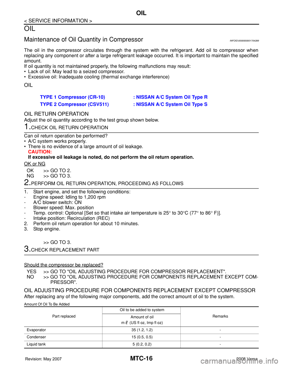
TYPE 1 Compressor (CR-10) : NISSAN A/C System Oil Type R
TYPE 2 Compressor (CSV511) : NISSAN A/C System Oil Type S
Part replacedOil to be added to system
Remarks
Amount of oil
m (US fl oz, Imp fl oz)
Evaporator 35 (1.2, 1.2) -
Condenser 15 (0.5, 0.5) -
Liquid tank 5 (0.2, 0.2) -
Page 2388 of 2771
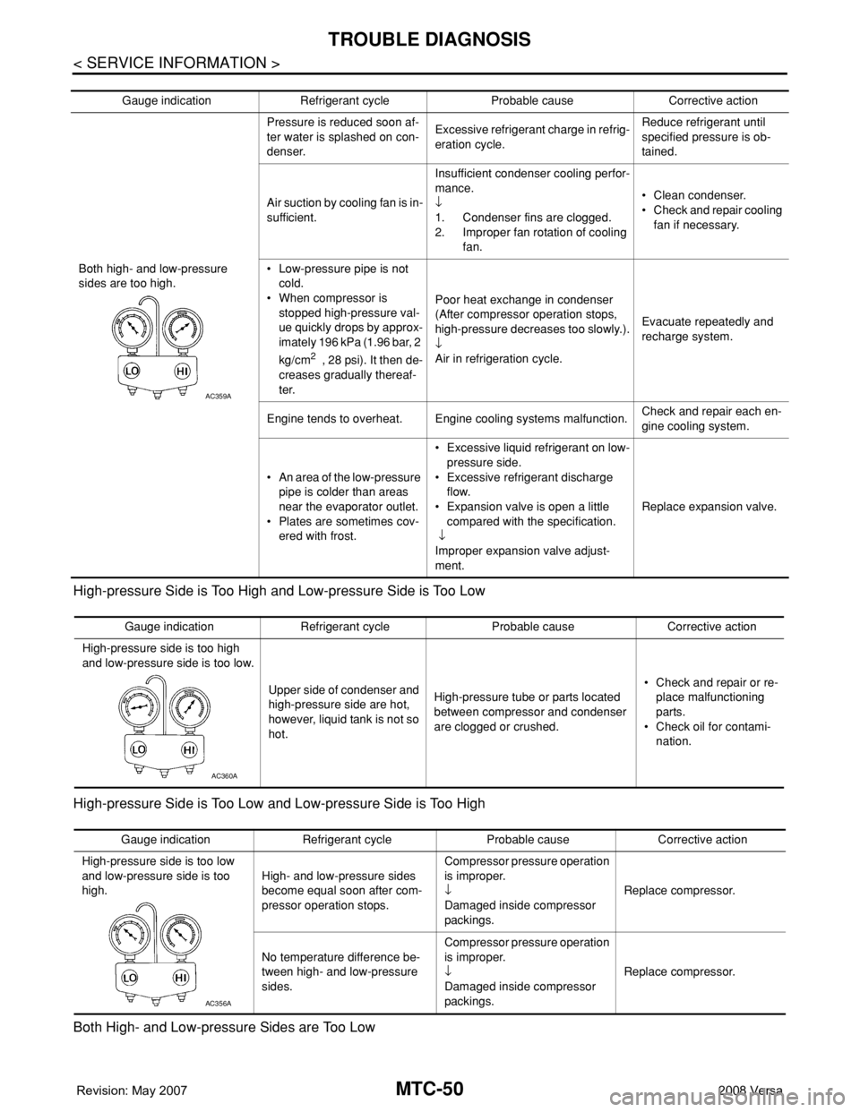
MTC-50
< SERVICE INFORMATION >
TROUBLE DIAGNOSIS
High-pressure Side is Too High and Low-pressure Side is Too Low
High-pressure Side is Too Low and Low-pressure Side is Too High
Both High- and Low-pressure Sides are Too Low
Gauge indication Refrigerant cycle Probable cause Corrective action
Both high- and low-pressure
sides are too high.Pressure is reduced soon af-
ter water is splashed on con-
denser.Excessive refrigerant charge in refrig-
eration cycle.Reduce refrigerant until
specified pressure is ob-
tained.
Air suction by cooling fan is in-
sufficient.Insufficient condenser cooling perfor-
mance.
↓
1. Condenser fins are clogged.
2. Improper fan rotation of cooling
fan.• Clean condenser.
• Check and repair cooling
fan if necessary.
• Low-pressure pipe is not
cold.
• When compressor is
stopped high-pressure val-
ue quickly drops by approx-
imately 196 kPa (1.96 bar, 2
kg/cm
2 , 28 psi). It then de-
creases gradually thereaf-
ter.Poor heat exchange in condenser
(After compressor operation stops,
high-pressure decreases too slowly.).
↓
Air in refrigeration cycle.Evacuate repeatedly and
recharge system.
Engine tends to overheat. Engine cooling systems malfunction.Check and repair each en-
gine cooling system.
• An area of the low-pressure
pipe is colder than areas
near the evaporator outlet.
• Plates are sometimes cov-
ered with frost.• Excessive liquid refrigerant on low-
pressure side.
• Excessive refrigerant discharge
flow.
• Expansion valve is open a little
compared with the specification.
↓
Improper expansion valve adjust-
ment.Replace expansion valve.
AC359A
Gauge indication Refrigerant cycle Probable cause Corrective action
High-pressure side is too high
and low-pressure side is too low.
Upper side of condenser and
high-pressure side are hot,
however, liquid tank is not so
hot.High-pressure tube or parts located
between compressor and condenser
are clogged or crushed.• Check and repair or re-
place malfunctioning
parts.
• Check oil for contami-
nation.
AC360A
Gauge indication Refrigerant cycle Probable cause Corrective action
High-pressure side is too low
and low-pressure side is too
high.High- and low-pressure sides
become equal soon after com-
pressor operation stops.Compressor pressure operation
is improper.
↓
Damaged inside compressor
packings.Replace compressor.
No temperature difference be-
tween high- and low-pressure
sides.Compressor pressure operation
is improper.
↓
Damaged inside compressor
packings.Replace compressor.
AC356A
Page 2389 of 2771
TROUBLE DIAGNOSIS
MTC-51
< SERVICE INFORMATION >
C
D
E
F
G
H
I
K
L
MA
B
MTC
N
O
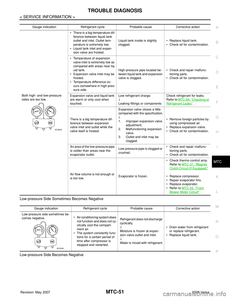
P Low-pressure Side Sometimes Becomes Negative
Low-pressure Side Becomes Negative
Gauge indication Refrigerant cycle Probable cause Corrective action
Both high- and low-pressure
sides are too low.• There is a big temperature dif-
ference between liquid tank
outlet and inlet. Outlet tem-
perature is extremely low.
• Liquid tank inlet and expan-
sion valve are frosted.Liquid tank inside is slightly
clogged.• Replace liquid tank.
• Check oil for contamination.
• Temperature of expansion
valve inlet is extremely low as
compared with areas near liq-
uid tank.
• Expansion valve inlet may be
frosted.
• Temperature difference oc-
curs somewhere in high-pres-
sure side.High-pressure pipe located be-
tween liquid tank and expansion
valve is clogged.• Check and repair malfunc-
tioning parts.
• Check oil for contamination.
Expansion valve and liquid tank
are warm or only cool when
touched.Low refrigerant charge.
↓
Leaking fittings or componentsCheck refrigerant for leaks.
Refer to MTC-84, "
Checking of
Refrigerant Leaks" .
There is a big temperature dif-
ference between expansion
valve inlet and outlet while the
valve itself is frosted.Expansion valve closes a little
compared with the specification.
↓
1. Improper expansion valve
adjustment.
2. Malfunctioning expansion
valve.
3. Outlet and inlet may be
clogged.• Remove foreign particles by
using compressed air.
• Replace expansion valve.
• Check oil for contamination.
An area of the low-pressure pipe
is colder than areas near the
evaporator outlet.Low-pressure pipe is clogged or
crushed.• Check and repair malfunc-
tioning parts.
• Check oil for contamination.
Air flow volume is not enough or
is too low.Evaporator is frozen.• Check thermo control amp.
Refer to MTC-37, "
Magnet
Clutch Circuit (If Equipped)"
.
• Replace compressor.
• Repair evaporator fins.
• Replace evaporator.
• Refer to MTC-33, "
Front
Blower Motor Circuit" .
AC353A
Gauge indication Refrigerant cycle Probable cause Corrective action
Low-pressure side sometimes be-
comes negative.• Air conditioning system does
not function and does not cy-
clically cool the compart-
ment air.
• The system constantly func-
tions for a certain period of
time after compressor is
stopped and restarted.Refrigerant does not discharge
cyclically.
↓
Moisture is frozen at expan-
sion valve outlet and inlet.
↓
Water is mixed with refrigerant.• Drain water from refrigerant
or replace refrigerant.
• Replace liquid tank.
AC354A
Page 2390 of 2771
MTC-52
< SERVICE INFORMATION >
TROUBLE DIAGNOSIS
Insufficient Heating
INFOID:0000000001704307
SYMPTOM: Insufficient heating
INSPECTION FLOW
1.CONFIRM SYMPTOM BY PERFORMING OPERATIONAL CHECK - TEMPERATURE DECREASE
1. Turn temperature control dial clockwise to maximum heat position.
2. Check for hot air at discharge air outlets.
Can the symptom be duplicated?
YES >> GO TO 3.
NO >> GO TO 2.
2.CHECK FOR ANY SYMPTOMS
Perform a complete operational check for any symptoms. Refer to MTC-30, "
Operational Check" .
Does another symptom exist?
YES >> Refer to MTC-22, "How to Perform Trouble Diagnosis for Quick and Accurate Repair" .
NO >> System OK.
3.CHECK FOR SERVICE BULLETINS
Check for any service bulletins.
>> GO TO 4.
4.CHECK COOLANT SYSTEM
1. Check engine coolant level. Refer to CO-8
.
2. Check hoses for leaks or kinks.
3. Check Radiator cap. Refer to CO-13, "
Checking Radiator Cap" .
OK or NG
OK >> GO TO 5.
NG >> Repair/replace as necessary.
5.CHECK AIR MIX DOOR CABLE
Check air mix door cable operation. Refer to MTC-64, "
Air Mix Door Cable Adjustment" .
OK or NG
YES >> GO TO 6.
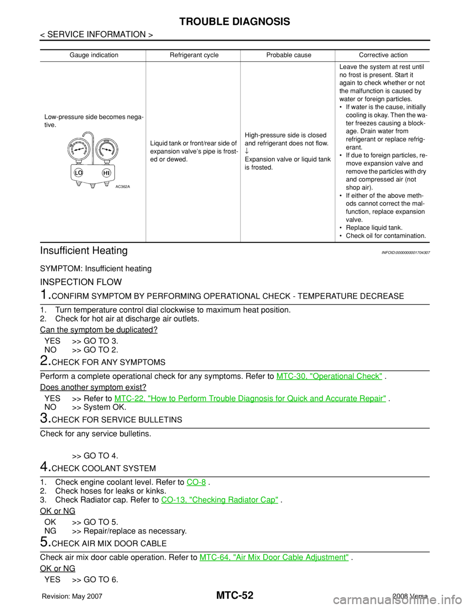
Gauge indication Refrigerant cycle Probable cause Corrective action
Low-pressure side becomes nega-
tive.
Liquid tank or front/rear side of
expansion valve’s pipe is frost-
ed or dewed.High-pressure side is closed
and refrigerant does not flow.
↓
Expansion valve or liquid tank
is frosted.Leave the system at rest until
no frost is present. Start it
again to check whether or not
the malfunction is caused by
water or foreign particles.
• If water is the cause, initially
cooling is okay. Then the wa-
ter freezes causing a block-
age. Drain water from
refrigerant or replace refrig-
erant.
• If due to foreign particles, re-
move expansion valve and
remove the particles with dry
and compressed air (not
shop air).
• If either of the above meth-
ods cannot correct the mal-
function, replace expansion
valve.
• Replace liquid tank.
• Check oil for contamination.
AC362A