Page 214 of 2771
AT-202
< SERVICE INFORMATION >
TRANSMISSION CONTROL MODULE
TRANSMISSION CONTROL MODULE
Removal and InstallationINFOID:0000000001703355
COMPONENTS
REMOVAL
1. Disconnect the battery negative terminal.
2. Disconnect TCM harness connectors (1) from TCM (2).
• Instrument lower finisher (3)
3. Remove TCM (2).
INSTALLATION
Installation is in the reverse order of removal.
1. TCM
SCIA6963E
SCIA7167E
Page 223 of 2771
A/T SHIFT LOCK SYSTEM
AT-211
< SERVICE INFORMATION >
D
E
F
G
H
I
J
K
L
MA
B
AT
N
O
P
•Selector lever can be moved from “P” position with ignition key in ON position and brake pedal
released.
•Selector lever can be moved from “P” position when ignition switch is removed from key cylinder.
SYMPTOM 2:
•Ignition key cannot be removed when selector lever is set to “P” position.
•Ignition key can be removed when selector lever is set to any position except “P” position.
1.CHECK KEY INTERLOCK CABLE
Check key interlock cable for damage.
OK or NG
OK >> GO TO 2.
NG >> Repair key interlock cable. Refer to AT-213, "
Removal and Installation" .
2.CHECK A/T POSITION
Check A/T position. Refer to AT-207, "
Checking of A/T Position" .
OK or NG
OK >> GO TO 3.
NG >> Adjust control cable. Refer to AT-207, "
Adjustment of A/T Position" .
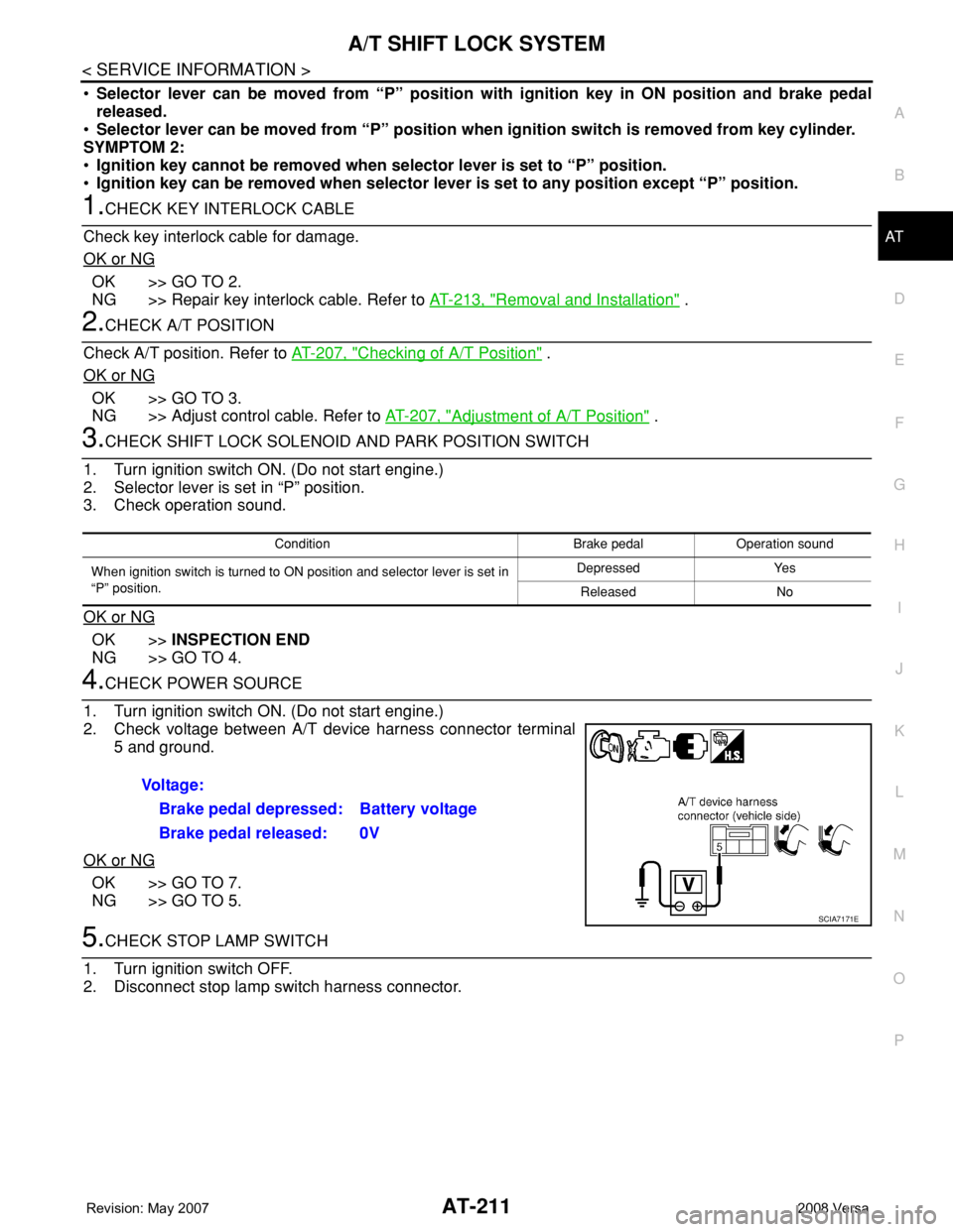
3.CHECK SHIFT LOCK SOLENOID AND PARK POSITION SWITCH
1. Turn ignition switch ON. (Do not start engine.)
2. Selector lever is set in “P” position.
3. Check operation sound.
OK or NG
OK >>INSPECTION END
NG >> GO TO 4.
4.CHECK POWER SOURCE
1. Turn ignition switch ON. (Do not start engine.)
2. Check voltage between A/T device harness connector terminal
5 and ground.
OK or NG
OK >> GO TO 7.
NG >> GO TO 5.
5.CHECK STOP LAMP SWITCH
1. Turn ignition switch OFF.
2. Disconnect stop lamp switch harness connector.
Condition Brake pedal Operation sound
When ignition switch is turned to ON position and selector lever is set in
“P” position.Depressed Yes
Released No
Voltage:
Brake pedal depressed: Battery voltage
Brake pedal released: 0V
SCIA7171E
Page 228 of 2771
AT-216
< SERVICE INFORMATION >
ON-VEHICLE SERVICE
ON-VEHICLE SERVICE
Control Valve Assembly and AccumulatorsINFOID:0000000001703366
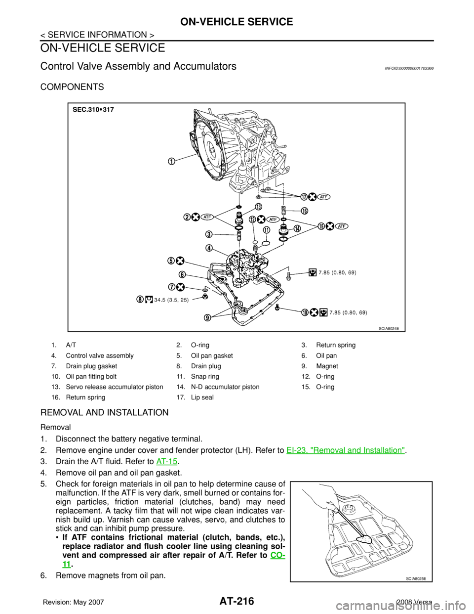
COMPONENTS
REMOVAL AND INSTALLATION
Removal
1. Disconnect the battery negative terminal.
2. Remove engine under cover and fender protector (LH). Refer to EI-23, "
Removal and Installation".
3. Drain the A/T fluid. Refer to AT- 1 5
.
4. Remove oil pan and oil pan gasket.
5. Check for foreign materials in oil pan to help determine cause of
malfunction. If the ATF is very dark, smell burned or contains for-
eign particles, friction material (clutches, band) may need
replacement. A tacky film that will not wipe clean indicates var-
nish build up. Varnish can cause valves, servo, and clutches to
stick and can inhibit pump pressure.
•If ATF contains frictional material (clutch, bands, etc.),
replace radiator and flush cooler line using cleaning sol-
vent and compressed air after repair of A/T. Refer to CO-
11.
6. Remove magnets from oil pan.
1. A/T 2. O-ring 3. Return spring
4. Control valve assembly 5. Oil pan gasket 6. Oil pan
7. Drain plug gasket 8. Drain plug 9. Magnet
10. Oil pan fitting bolt 11. Snap ring 12. O-ring
13. Servo release accumulator piston 14. N-D accumulator piston 15. O-ring
16. Return spring 17. Lip seal
SCIA8024E
SCIA8025E
Page 232 of 2771
AT-220
< SERVICE INFORMATION >
ON-VEHICLE SERVICE
REMOVAL AND INSTALLATION
Removal
1. Disconnect the battery negative terminal.
2. Remove air duct (inlet). Refer to EM-16
.
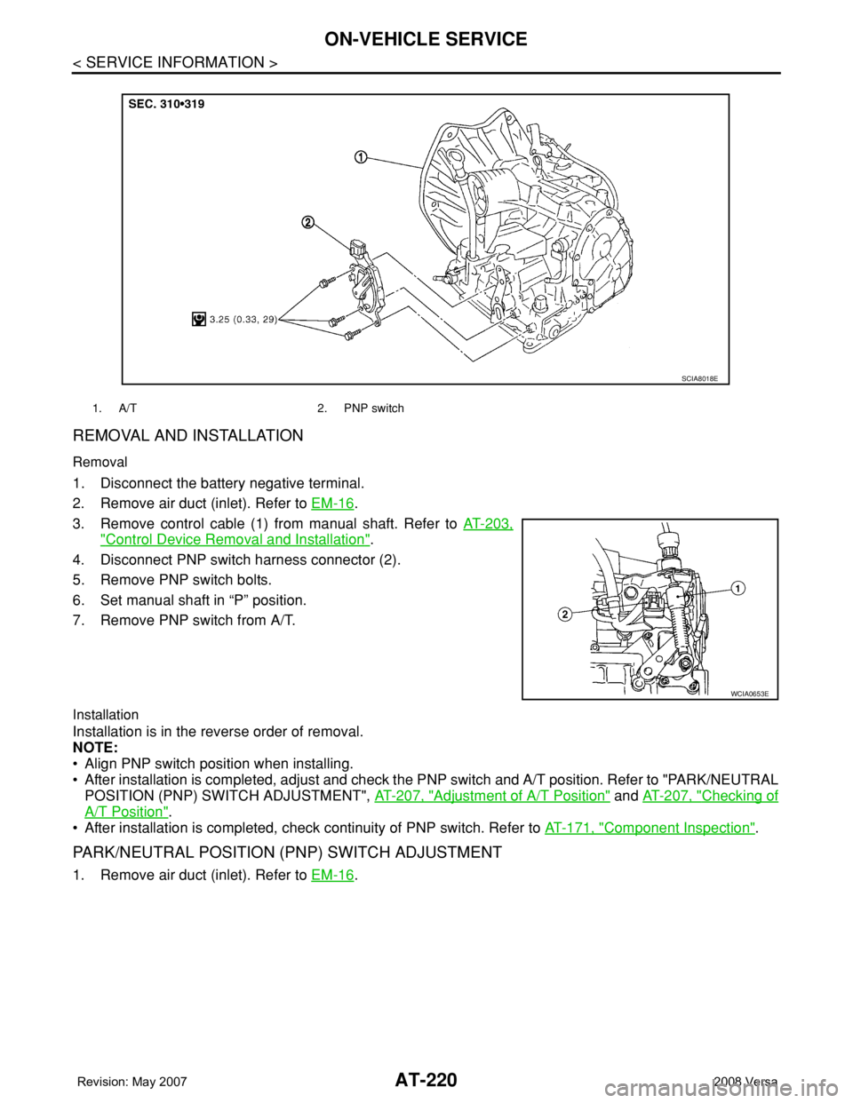
3. Remove control cable (1) from manual shaft. Refer to AT-203,
"Control Device Removal and Installation".
4. Disconnect PNP switch harness connector (2).
5. Remove PNP switch bolts.
6. Set manual shaft in “P” position.
7. Remove PNP switch from A/T.
Installation
Installation is in the reverse order of removal.
NOTE:
• Align PNP switch position when installing.
• After installation is completed, adjust and check the PNP switch and A/T position. Refer to "PARK/NEUTRAL
POSITION (PNP) SWITCH ADJUSTMENT", AT-207, "
Adjustment of A/T Position" and AT-207, "Checking of
A/T Position".
• After installation is completed, check continuity of PNP switch. Refer to AT-171, "
Component Inspection".
PARK/NEUTRAL POSITION (PNP) SWITCH ADJUSTMENT
1. Remove air duct (inlet). Refer to EM-16.
1. A/T 2. PNP switch
SCIA8018E
WCIA0653E
Page 233 of 2771
ON-VEHICLE SERVICE
AT-221
< SERVICE INFORMATION >
D
E
F
G
H
I
J
K
L
MA
B
AT
N
O
P
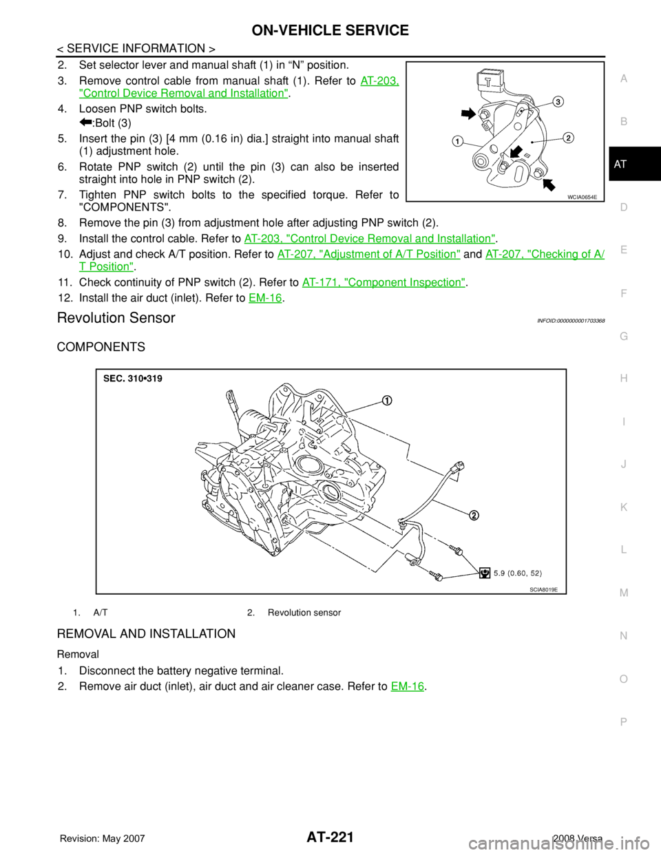
2. Set selector lever and manual shaft (1) in “N” position.
3. Remove control cable from manual shaft (1). Refer to AT-203,
"Control Device Removal and Installation".
4. Loosen PNP switch bolts.
:Bolt (3)
5. Insert the pin (3) [4 mm (0.16 in) dia.] straight into manual shaft
(1) adjustment hole.
6. Rotate PNP switch (2) until the pin (3) can also be inserted
straight into hole in PNP switch (2).
7. Tighten PNP switch bolts to the specified torque. Refer to
"COMPONENTS".
8. Remove the pin (3) from adjustment hole after adjusting PNP switch (2).
9. Install the control cable. Refer to AT-203, "
Control Device Removal and Installation".
10. Adjust and check A/T position. Refer to AT-207, "
Adjustment of A/T Position" and AT-207, "Checking of A/
T Position".
11. Check continuity of PNP switch (2). Refer to AT-171, "
Component Inspection".
12. Install the air duct (inlet). Refer to EM-16
.
Revolution SensorINFOID:0000000001703368
COMPONENTS
REMOVAL AND INSTALLATION
Removal
1. Disconnect the battery negative terminal.
2. Remove air duct (inlet), air duct and air cleaner case. Refer to EM-16
.
WCIA0654E
1. A/T 2. Revolution sensor
SCIA8019E
Page 234 of 2771
AT-222
< SERVICE INFORMATION >
ON-VEHICLE SERVICE
3. Disconnect revolution sensor harness connector.
4. Remove clip (A).
5. Remove revolution sensor (1) from A/T.
: Bolt (2)
6. Remove O-ring from revolution sensor (1)
Installation
Installation is in the reverse order of removal.
CAUTION:
• Do not reuse O-ring.
• Apply ATF to O-ring.
• Ensure revolution sensor harness is firmly secured with bolt.
(1): Revolution sensor
: Bolt (1)
Turbine Revolution Sensor (Power Train Revolution Sensor)INFOID:0000000001703369
COMPONENTS
REMOVAL AND INSTALLATION
Removal
1. Disconnect the battery negative terminal.
2. Remove air duct (inlet). Refer to EM-16
.
WCIA0655E
WCIA0656E
1. A/T 2. O-ring 3. Turbine revolution sensor (power
train revolution sensor)
SCIA8020E
Page 374 of 2771
AUDIO
AV-15
< SERVICE INFORMATION >
C
D
E
F
G
H
I
J
L
MA
B
AV
N
O
P
Audio Unit (Base System) Harness Connector Terminal LayoutINFOID:0000000001704653
Terminal and Reference Value for Audio Unit (Base System)INFOID:0000000001704654
WKIA5439E
Te r m i n a l
(Wire color)
ItemSignal
input/
outputCondition
Reference value
(Approx.)
+–Ignition
switchOperation
2 (W) 3 (BR) Audio signal front LH Output ON Receive audio signal
4 (V) 5 (R) Audio signal rear LH Output ON Receive audio signal
7 (LG) Ground ACC power supply Input ACC – Battery voltage
11 (G) 12 (SB) Audio signal front RH Output ON Receive audio signal
13 (LG) 14 (GR) Audio signal rear RH Output ON Receive audio signal
19 (BR) Ground Battery power supply Input OFF – Battery voltage
SKIB3609E
SKIB3609E
SKIB3609E
SKIB3609E
Page 375 of 2771
AV-16
< SERVICE INFORMATION >
AUDIO
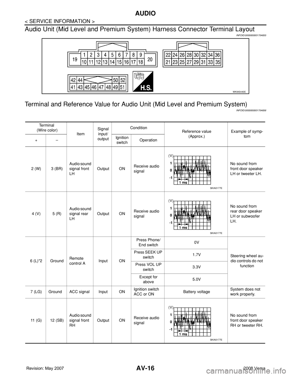
Audio Unit (Mid Level and Premium System) Harness Connector Terminal Layout
INFOID:0000000001704655
Terminal and Reference Value for Audio Unit (Mid Level and Premium System)
INFOID:0000000001704656
WKIA5440E
Te r m i n a l
(Wire color)
ItemSignal
input/
outputCondition
Reference value
(Approx.)Example of symp-
tom
+–Ignition
switchOperation
2 (W) 3 (BR)Audio sound
signal front
LHOutput ONReceive audio
signalNo sound from
front door speaker
LH or tweeter LH.
4 (V) 5 (R)Audio sound
signal rear
LHOutput ONReceive audio
signalNo sound from
rear door speaker
LH or subwoofer
LH.
6 (L)*2 GroundRemote
control AInput ONPress Phone/
End switch0V
Steering wheel au-
dio controls do not
function Press SEEK UP
switch1.7V
Press VOL UP
switch3.3V
Except for
above5.0V
7 (LG) Ground ACC signal Input ONIgnition switch
ACC or ONBattery voltageSystem does not
work properly.
11 (G) 12 (SB)Audio sound
signal front
RHOutput ONReceive audio
signalNo sound from
front door speaker
RH or tweeter RH.
SKIA0177E
SKIA0177E
SKIA0177E