2008 NISSAN LATIO check oil
[x] Cancel search: check oilPage 767 of 2771
![NISSAN LATIO 2008 Service Repair Manual BRC-2
< SERVICE INFORMATION >[ABS]
PRECAUTIONS
SERVICE INFORMATION
PRECAUTIONS
Precaution for Supplemental Restraint System (SRS) "AIR BAG" and "SEAT BELT
PRE-TENSIONER"
INFOID:000000 NISSAN LATIO 2008 Service Repair Manual BRC-2
< SERVICE INFORMATION >[ABS]
PRECAUTIONS
SERVICE INFORMATION
PRECAUTIONS
Precaution for Supplemental Restraint System (SRS) "AIR BAG" and "SEAT BELT
PRE-TENSIONER"
INFOID:000000](/manual-img/5/57360/w960_57360-766.png)
BRC-2
< SERVICE INFORMATION >[ABS]
PRECAUTIONS
SERVICE INFORMATION
PRECAUTIONS
Precaution for Supplemental Restraint System (SRS) "AIR BAG" and "SEAT BELT
PRE-TENSIONER"
INFOID:0000000001703818
The Supplemental Restraint System such as “AIR BAG” and “SEAT BELT PRE-TENSIONER”, used along
with a front seat belt, helps to reduce the risk or severity of injury to the driver and front passenger for certain
types of collision. This system includes seat belt switch inputs and dual stage front air bag modules. The SRS
system uses the seat belt switches to determine the front air bag deployment, and may only deploy one front
air bag, depending on the severity of a collision and whether the front occupants are belted or unbelted.
Information necessary to service the system safely is included in the SRS and SB section of this Service Man-
ual.
WARNING:
• To avoid rendering the SRS inoperative, which could increase the risk of personal injury or death in
the event of a collision which would result in air bag inflation, all maintenance must be performed by
an authorized NISSAN/INFINITI dealer.
• Improper maintenance, including incorrect removal and installation of the SRS, can lead to personal
injury caused by unintentional activation of the system. For removal of Spiral Cable and Air Bag
Module, see the SRS section.
• Do not use electrical test equipment on any circuit related to the SRS unless instructed to in this
Service Manual. SRS wiring harnesses can be identified by yellow and/or orange harnesses or har-
ness connectors.
Precaution for Brake SystemINFOID:0000000001703819
CAUTION:
• Refer to MA-10
for recommended brake fluid.
• Never reuse drained brake fluid.
• Be careful not to splash brake fluid on painted areas; it may cause paint damage. If brake fluid is
splashed on painted areas, wash it away with water immediately.
• To clean or wash all parts of master cylinder and disc brake caliper, use clean brake fluid.
• Never use mineral oils such as gasoline or kerosene. They will ruin rubber parts of the hydraulic sys-
tem.
• Use flare nut wrench when removing and installing brake
tube.
• If a brake fluid leak is found, the part must be disassembled
without fail. Then it has to be replaced with a new one if a
defect exists.
• Turn the ignition switch OFF and remove the connector of the
ABS actuator and electric unit (control unit) or the battery ter-
minal before performing the work.
• Always torque brake lines when installing.
• Burnish the brake contact surfaces after refinishing or replac-
ing rotors, after replacing pads, or if a soft pedal occurs at
very low mileage. Refer to BR-28, "
Brake Burnishing Proce-
dure".
WARNING:
• Clean brake pads and shoes with a waste cloth, then wipe with a dust collector.
Precaution for Brake ControlINFOID:0000000001703821
• During ABS operation, the brake pedal may vibrate lightly and a mechanical noise may be heard. This is
normal.
• Just after starting the vehicle, the brake pedal may vibrate or motor operating noises may be heard from
engine compartment. This is normal due to the self check operation.
• Stopping distance may be longer than that of vehicles without ABS when vehicle drives on rough, gravel, or
snow-covered (fresh, deep snow) roads.
SBR686C
Page 814 of 2771
CLUTCH DISC, CLUTCH COVER AND FLYWHEEL
CL-13
< SERVICE INFORMATION >
D
E
F
G
H
I
J
K
L
MA
B
CL
N
O
P
CLUTCH DISC, CLUTCH COVER AND FLYWHEEL
Removal and InstallationINFOID:0000000001703123
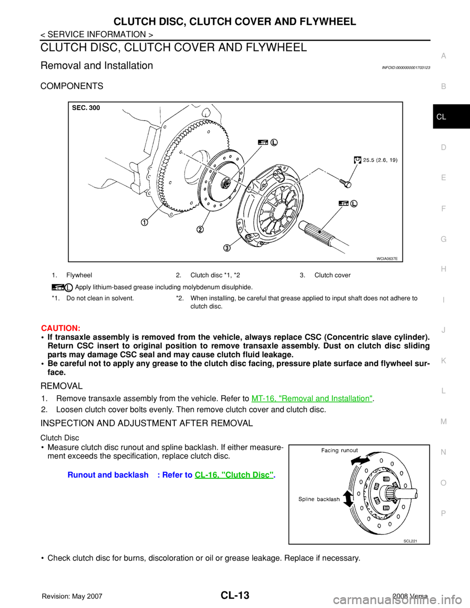
COMPONENTS
CAUTION:
• If transaxle assembly is removed from the vehicle, always replace CSC (Concentric slave cylinder).
Return CSC insert to original position to remove transaxle assembly. Dust on clutch disc sliding
parts may damage CSC seal and may cause clutch fluid leakage.
• Be careful not to apply any grease to the clutch disc facing, pressure plate surface and flywheel sur-
face.
REMOVAL
1. Remove transaxle assembly from the vehicle. Refer to MT-16, "Removal and Installation".
2. Loosen clutch cover bolts evenly. Then remove clutch cover and clutch disc.
INSPECTION AND ADJUSTMENT AFTER REMOVAL
Clutch Disc
• Measure clutch disc runout and spline backlash. If either measure-
ment exceeds the specification, replace clutch disc.
• Check clutch disc for burns, discoloration or oil or grease leakage. Replace if necessary.
1. Flywheel 2. Clutch disc *1, *2 3. Clutch cover
Apply lithium-based grease including molybdenum disulphide.
*1. Do not clean in solvent. *2. When installing, be careful that grease applied to input shaft does not adhere to
clutch disc.
WCIA0637E
Runout and backlash : Refer to CL-16, "Clutch Disc".
SCL221
Page 830 of 2771
RADIATOR
CO-13
< SERVICE INFORMATION >
C
D
E
F
G
H
I
J
K
L
MA
CO
N
P O
Checking Radiator CapINFOID:0000000001702533
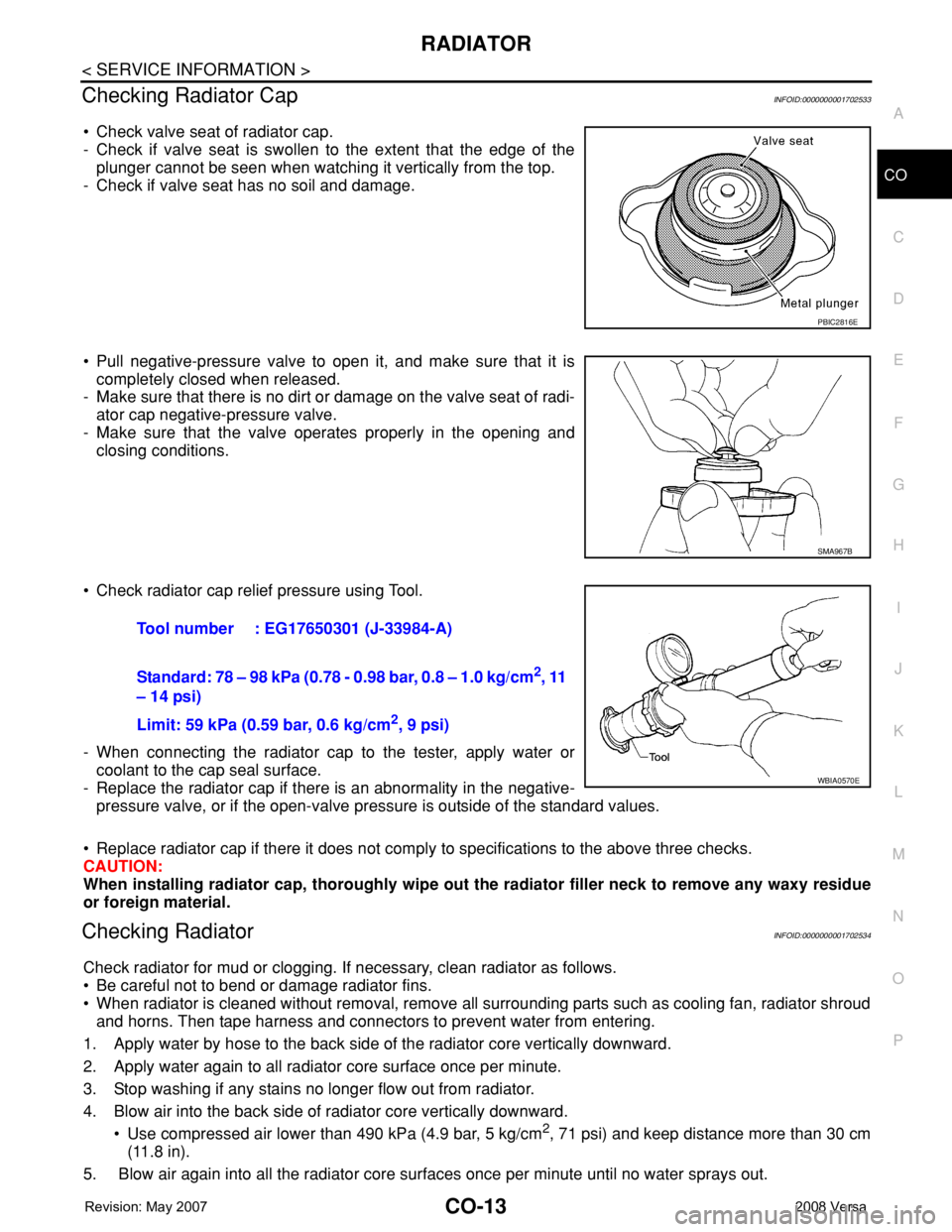
• Check valve seat of radiator cap.
- Check if valve seat is swollen to the extent that the edge of the
plunger cannot be seen when watching it vertically from the top.
- Check if valve seat has no soil and damage.
• Pull negative-pressure valve to open it, and make sure that it is
completely closed when released.
- Make sure that there is no dirt or damage on the valve seat of radi-
ator cap negative-pressure valve.
- Make sure that the valve operates properly in the opening and
closing conditions.
• Check radiator cap relief pressure using Tool.
- When connecting the radiator cap to the tester, apply water or
coolant to the cap seal surface.
- Replace the radiator cap if there is an abnormality in the negative-
pressure valve, or if the open-valve pressure is outside of the standard values.
• Replace radiator cap if there it does not comply to specifications to the above three checks.
CAUTION:
When installing radiator cap, thoroughly wipe out the radiator filler neck to remove any waxy residue
or foreign material.
Checking RadiatorINFOID:0000000001702534
Check radiator for mud or clogging. If necessary, clean radiator as follows.
• Be careful not to bend or damage radiator fins.
• When radiator is cleaned without removal, remove all surrounding parts such as cooling fan, radiator shroud
and horns. Then tape harness and connectors to prevent water from entering.
1. Apply water by hose to the back side of the radiator core vertically downward.
2. Apply water again to all radiator core surface once per minute.
3. Stop washing if any stains no longer flow out from radiator.
4. Blow air into the back side of radiator core vertically downward.
• Use compressed air lower than 490 kPa (4.9 bar, 5 kg/cm
2, 71 psi) and keep distance more than 30 cm
(11.8 in).
5. Blow air again into all the radiator core surfaces once per minute until no water sprays out.
PBIC2816E
SMA967B
Tool number : EG17650301 (J-33984-A)
Standard: 78 – 98 kPa (0.78 - 0.98 bar, 0.8 – 1.0 kg/cm
2, 11
– 14 psi)
Limit: 59 kPa (0.59 bar, 0.6 kg/cm
2, 9 psi)
WBIA0570E
Page 834 of 2771
THERMOSTAT
CO-17
< SERVICE INFORMATION >
C
D
E
F
G
H
I
J
K
L
MA
CO
N
P O
THERMOSTAT
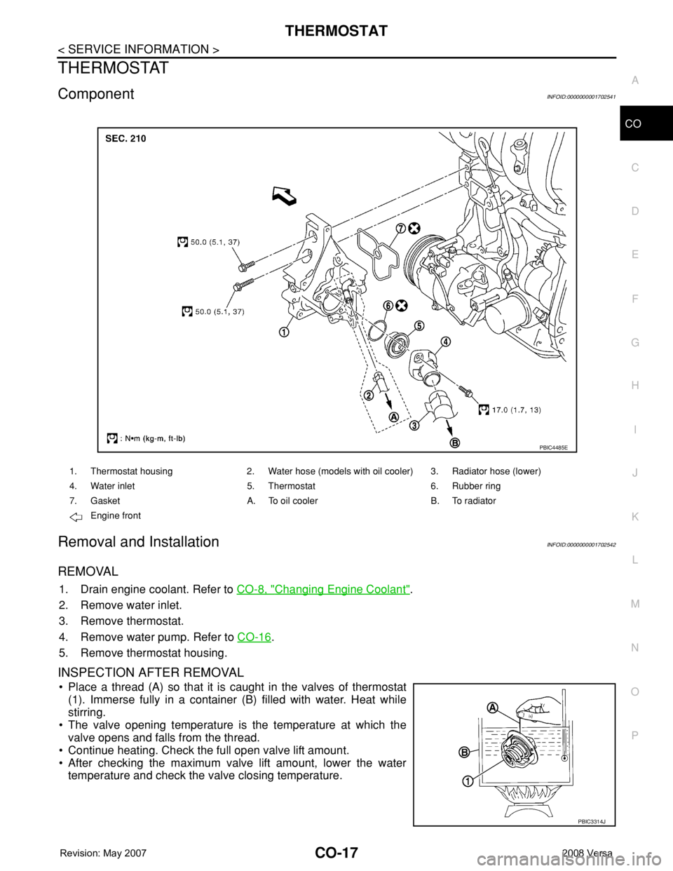
ComponentINFOID:0000000001702541
Removal and InstallationINFOID:0000000001702542
REMOVAL
1. Drain engine coolant. Refer to CO-8, "Changing Engine Coolant".
2. Remove water inlet.
3. Remove thermostat.
4. Remove water pump. Refer to CO-16
.
5. Remove thermostat housing.
INSPECTION AFTER REMOVAL
• Place a thread (A) so that it is caught in the valves of thermostat
(1). Immerse fully in a container (B) filled with water. Heat while
stirring.
• The valve opening temperature is the temperature at which the
valve opens and falls from the thread.
• Continue heating. Check the full open valve lift amount.
• After checking the maximum valve lift amount, lower the water
temperature and check the valve closing temperature.
1. Thermostat housing 2. Water hose (models with oil cooler) 3. Radiator hose (lower)
4. Water inlet 5. Thermostat 6. Rubber ring
7. Gasket A. To oil cooler B. To radiator
Engine front
PBIC4485E
PBIC3314J
Page 843 of 2771

CVT-4
DTC P1740 LOCK-UP SELECT SOLENOID
VALVE CIRCUIT ..............................................
132
Description .............................................................132
CONSULT-III Reference Value in Data Monitor
Mode ......................................................................
132
On Board Diagnosis Logic .....................................132
Possible Cause ......................................................132
DTC Confirmation Procedure ................................132
Wiring Diagram - CVT - L/USSV ............................133
Diagnosis Procedure .............................................134
Component Inspection ...........................................135
DTC P1745 LINE PRESSURE CONTROL ......136
Description .............................................................136
On Board Diagnosis Logic .....................................136
Possible Cause ......................................................136
DTC Confirmation Procedure ................................136
Diagnosis Procedure .............................................136
DTC P1777 STEP MOTOR - CIRCUIT ............137
Description .............................................................137
CONSULT-III Reference Value in Data Monitor
Mode ......................................................................
137
On Board Diagnosis Logic .....................................137
Possible Cause ......................................................137
DTC Confirmation Procedure ................................137
Wiring Diagram - CVT - STM .................................138
Diagnosis Procedure .............................................139
Component Inspection ...........................................140
DTC P1778 STEP MOTOR - FUNCTION ........141
Description .............................................................141
CONSULT-III Reference Value in Data Monitor
Mode ......................................................................
141
On Board Diagnosis Logic .....................................141
Possible Cause ......................................................141
DTC Confirmation Procedure ................................141
Diagnosis Procedure .............................................142
OVERDRIVE CONTROL SWITCH ..................143
Description .............................................................143
CONSULT-III Reference Value in Data Monitor
Mode ......................................................................
143
Wiring Diagram - CVT - ODSW .............................144
Diagnosis Procedure .............................................144
Component Inspection ...........................................146
SHIFT POSITION INDICATOR CIRCUIT ........148
Description .............................................................148
CONSULT-III Reference Value in Data Monitor
Mode ......................................................................
148
Diagnosis Procedure .............................................148
TROUBLE DIAGNOSIS FOR SYMPTOMS .....149
Wiring Diagram - CVT - NONDTC .........................149
O/D OFF Indicator Lamp Does Not Come On ......151
Engine Cannot Be Started in "P" and "N" Position .153
In "P" Position, Vehicle Moves Forward or Back-
ward When Pushed ...............................................
153
In "N" Position, Vehicle Moves ..............................154
Large Shock "N" → "R" Position ...........................154
Vehicle Does Not Creep Backward in "R" Position .155
Vehicle Does Not Creep Forward in "D" or "L" Po-
sition ......................................................................
156
Vehicle Speed Does Not Change in "L" Position ..157
Vehicle Speed Does Not Change in overdrive-off
mode .....................................................................
158
Vehicle Speed Does Not Change in "D" Position .159
Vehicle Does Not Decelerate by Engine Brake ....159
TRANSMISSION CONTROL MODULE ...........161
Removal and Installation .......................................161
CVT SHIFT LOCK SYSTEM .............................162
Description ............................................................162
Shift Lock System Electrical Parts Location ..........162
Wiring Diagram - CVT - SHIFT .............................163
Diagnosis Procedure .............................................163
SHIFT CONTROL SYSTEM .............................167
Removal and Installation .......................................167
Control Device Disassembly and Assembly .........170
Selector Lever Knob Removal and Installation .....170
Adjustment of CVT Position ..................................171
Checking of CVT Position .....................................171
KEY INTERLOCK CABLE ...............................173
Removal and Installation .......................................173
AIR BREATHER HOSE ....................................176
Removal and Installation .......................................176
DIFFERENTIAL SIDE OIL SEAL .....................177
Removal and Installation .......................................177
TRANSAXLE ASSEMBLY ...............................178
Removal and Installation .......................................178
SERVICE DATA AND SPECIFICATIONS
(SDS) ................................................................
181
General Specification ............................................181
Vehicle Speed When Shifting Gears .....................181
Stall Speed ............................................................181
Line Pressure ........................................................181
Solenoid Valves ....................................................182
CVT Fluid Temperature Sensor ............................182
Primary Speed Sensor ..........................................182
Secondary Speed Sensor .....................................182
Removal and Installation .......................................182
Page 853 of 2771
CVT-14
< SERVICE INFORMATION >
CVT FLUID
FLUID CONDITION CHECK
Changing CVT FluidINFOID:0000000001703434
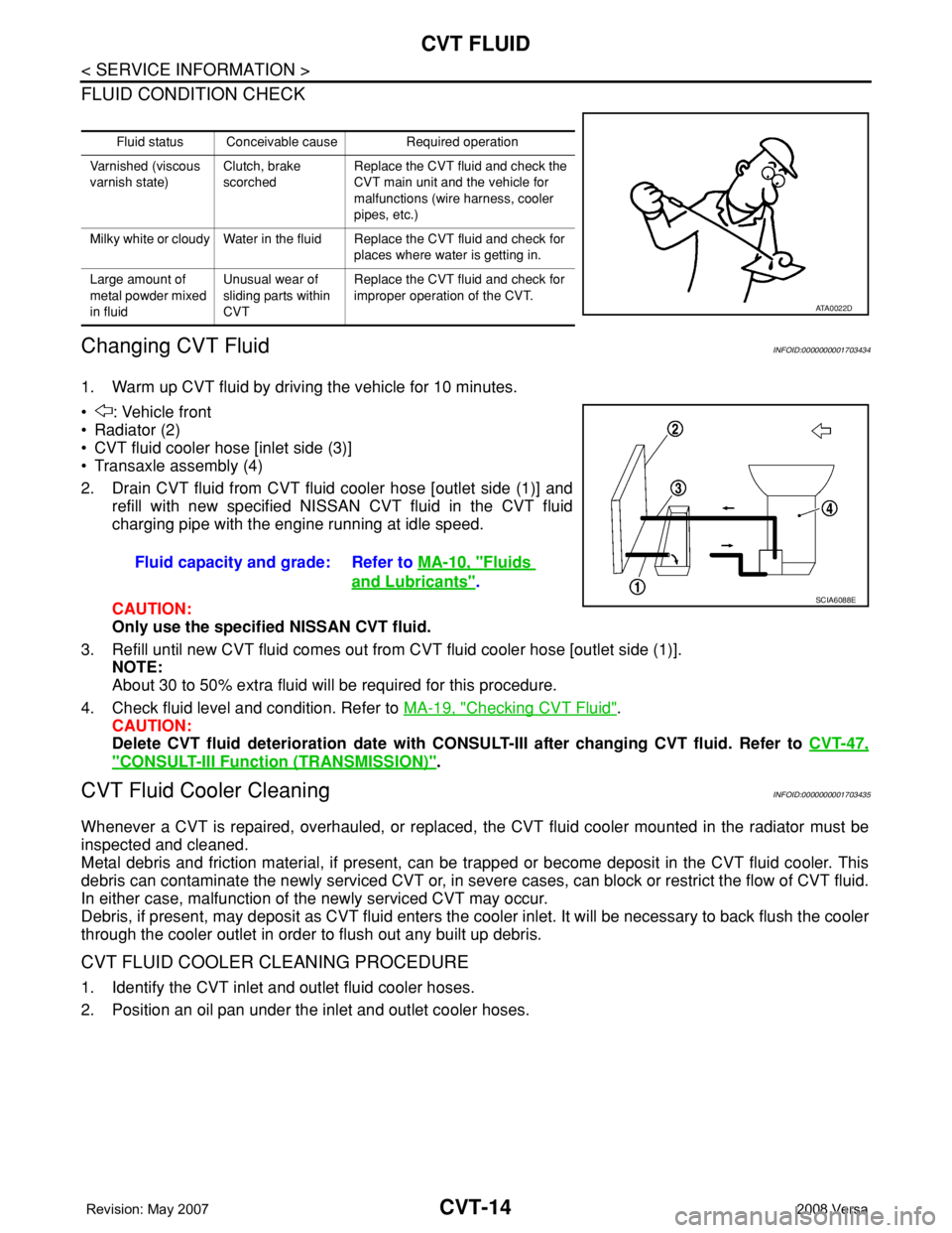
1. Warm up CVT fluid by driving the vehicle for 10 minutes.
• : Vehicle front
• Radiator (2)
• CVT fluid cooler hose [inlet side (3)]
• Transaxle assembly (4)
2. Drain CVT fluid from CVT fluid cooler hose [outlet side (1)] and
refill with new specified NISSAN CVT fluid in the CVT fluid
charging pipe with the engine running at idle speed.
CAUTION:
Only use the specified NISSAN CVT fluid.
3. Refill until new CVT fluid comes out from CVT fluid cooler hose [outlet side (1)].
NOTE:
About 30 to 50% extra fluid will be required for this procedure.
4. Check fluid level and condition. Refer to MA-19, "
Checking CVT Fluid".
CAUTION:
Delete CVT fluid deterioration date with CONSULT-III after changing CVT fluid. Refer to CVT-47,
"CONSULT-III Function (TRANSMISSION)".
CVT Fluid Cooler CleaningINFOID:0000000001703435
Whenever a CVT is repaired, overhauled, or replaced, the CVT fluid cooler mounted in the radiator must be
inspected and cleaned.
Metal debris and friction material, if present, can be trapped or become deposit in the CVT fluid cooler. This
debris can contaminate the newly serviced CVT or, in severe cases, can block or restrict the flow of CVT fluid.
In either case, malfunction of the newly serviced CVT may occur.
Debris, if present, may deposit as CVT fluid enters the cooler inlet. It will be necessary to back flush the cooler
through the cooler outlet in order to flush out any built up debris.
CVT FLUID COOLER CLEANING PROCEDURE
1. Identify the CVT inlet and outlet fluid cooler hoses.
2. Position an oil pan under the inlet and outlet cooler hoses.
Fluid status Conceivable cause Required operation
Varnished (viscous
varnish state)Clutch, brake
scorchedReplace the CVT fluid and check the
CVT main unit and the vehicle for
malfunctions (wire harness, cooler
pipes, etc.)
Milky white or cloudy Water in the fluid Replace the CVT fluid and check for
places where water is getting in.
Large amount of
metal powder mixed
in fluidUnusual wear of
sliding parts within
CVTReplace the CVT fluid and check for
improper operation of the CVT.
ATA0022D
Fluid capacity and grade: Refer to MA-10, "Fluids
and Lubricants".SCIA6088E
Page 876 of 2771
TROUBLE DIAGNOSIS
CVT-37
< SERVICE INFORMATION >
D
E
F
G
H
I
J
K
L
MA
B
CVT
N
O
P
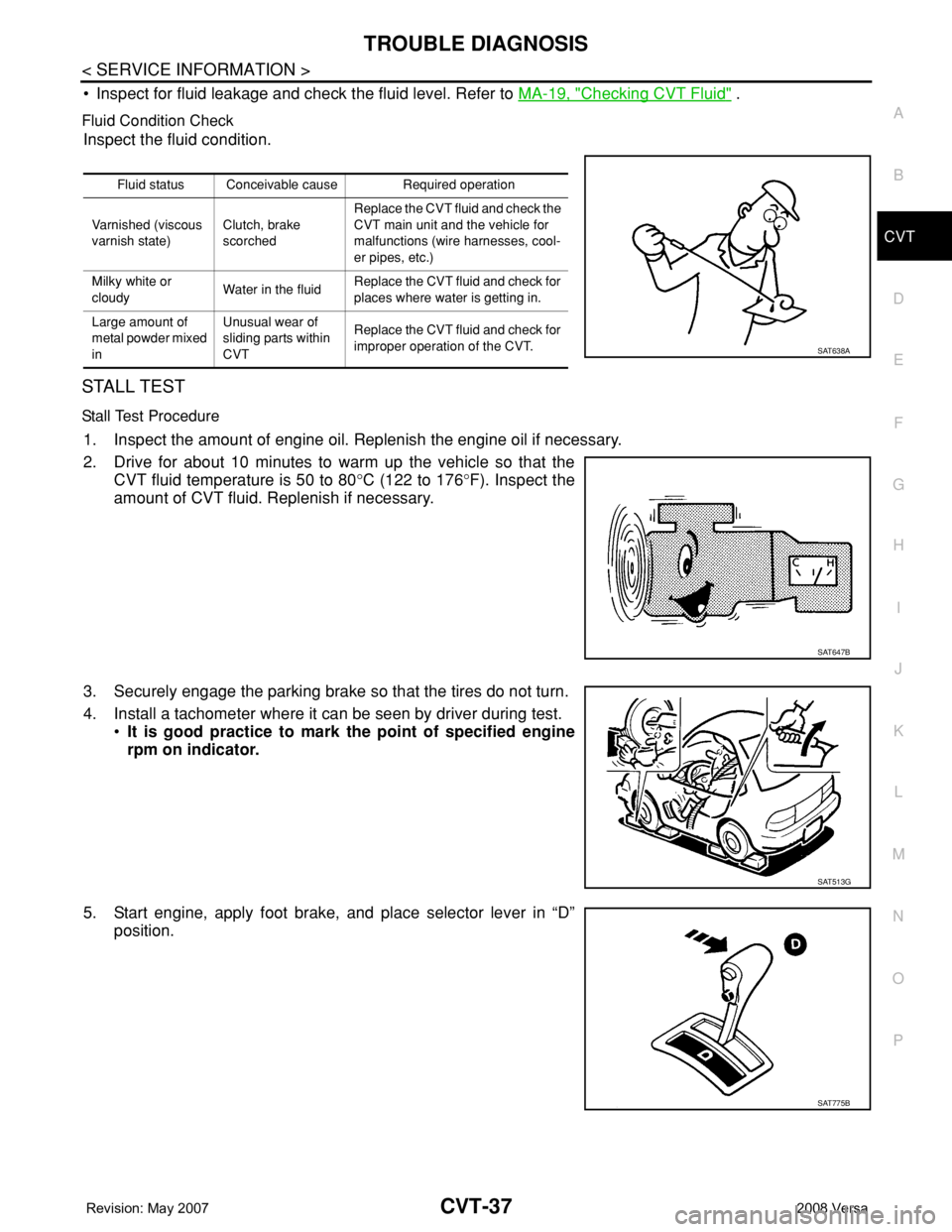
• Inspect for fluid leakage and check the fluid level. Refer to MA-19, "Checking CVT Fluid" .
Fluid Condition Check
Inspect the fluid condition.
STALL TEST
Stall Test Procedure
1. Inspect the amount of engine oil. Replenish the engine oil if necessary.
2. Drive for about 10 minutes to warm up the vehicle so that the
CVT fluid temperature is 50 to 80°C (122 to 176°F). Inspect the
amount of CVT fluid. Replenish if necessary.
3. Securely engage the parking brake so that the tires do not turn.
4. Install a tachometer where it can be seen by driver during test.
•It is good practice to mark the point of specified engine
rpm on indicator.
5. Start engine, apply foot brake, and place selector lever in “D”
position.
Fluid status Conceivable cause Required operation
Varnished (viscous
varnish state)Clutch, brake
scorchedReplace the CVT fluid and check the
CVT main unit and the vehicle for
malfunctions (wire harnesses, cool-
er pipes, etc.)
Milky white or
cloudyWater in the fluidReplace the CVT fluid and check for
places where water is getting in.
Large amount of
metal powder mixed
inUnusual wear of
sliding parts within
CVTReplace the CVT fluid and check for
improper operation of the CVT.
SAT638A
SAT647B
SAT513G
SAT775B
Page 879 of 2771
CVT-40
< SERVICE INFORMATION >
TROUBLE DIAGNOSIS
Road Test
INFOID:0000000001703457
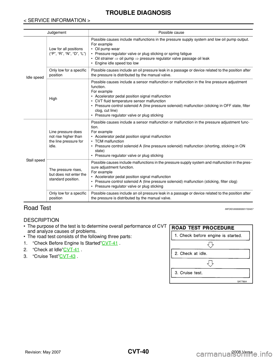
DESCRIPTION
• The purpose of the test is to determine overall performance of CVT
and analyze causes of problems.
• The road test consists of the following three parts:
1. “Check Before Engine Is Started”CVT-41
.
2. “Check at Idle”CVT-41
.
3. “Cruise Test”CVT-43
.
Judgement Possible cause
Idle speedLow for all positions
(“P”, “R”, “N”, “D”, “L”)Possible causes include malfunctions in the pressure supply system and low oil pump output.
For example
•Oil pump wear
• Pressure regulator valve or plug sticking or spring fatigue
•Oil strainer ⇒ oil pump ⇒ pressure regulator valve passage oil leak
• Engine idle speed too low
Only low for a specific
positionPossible causes include an oil pressure leak in a passage or device related to the position after
the pressure is distributed by the manual valve.
HighPossible causes include a sensor malfunction or malfunction in the line pressure adjustment
function.
For example
• Accelerator pedal position signal malfunction
• CVT fluid temperature sensor malfunction
• Pressure control solenoid A (line pressure solenoid) malfunction (sticking in OFF state, filter
clog, cut line)
• Pressure regulator valve or plug sticking
Sta ll sp ee dLine pressure does
not rise higher than
the line pressure for
idle.Possible causes include a sensor malfunction or malfunction in the pressure adjustment func-
tion.
For example
• Accelerator pedal position signal malfunction
•TCM malfunction
• Pressure control solenoid A (line pressure solenoid) malfunction (shorting, sticking in ON
state)
• Pressure regulator valve or plug sticking
The pressure rises,
but does not enter the
standard position.Possible causes include malfunctions in the pressure supply system and malfunction in the pres-
sure adjustment function.
For example
• Accelerator pedal position signal malfunction
• Pressure control solenoid A (line pressure solenoid) malfunction (sticking, filter clog)
• Pressure regulator valve or plug sticking
Only low for a specific
positionPossible causes include an oil pressure leak in a passage or device related to the position after
the pressure is distributed by the manual valve.
SAT786A