2008 NISSAN LATIO check oil
[x] Cancel search: check oilPage 882 of 2771
TROUBLE DIAGNOSIS
CVT-43
< SERVICE INFORMATION >
D
E
F
G
H
I
J
K
L
MA
B
CVT
N
O
P
Cruise TestINFOID:0000000001703460
1.CHECK VEHICLE SPEED WHEN SHIFTING GEARS — PART 1
1. Drive vehicle for approximately 10 minutes to warm engine oil and CVT fluid up to operating temperature.
2. Park vehicle on flat surface.
3. Move selector lever to “P” position.
4. Start engine.
5. Move selector lever to “L” position.
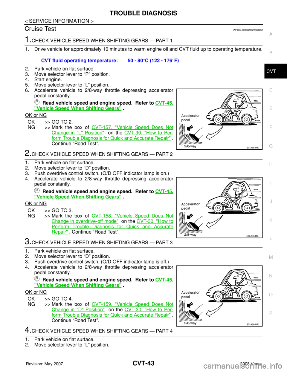
6. Accelerate vehicle to 2/8-way throttle depressing accelerator
pedal constantly.
Read vehicle speed and engine speed. Refer to CVT-45,
"Vehicle Speed When Shifting Gears" .
OK or NG
OK >> GO TO 2.
NG >> Mark the box of CVT-157, "
Vehicle Speed Does Not
Change in "L" Position" on the CVT-30, "How to Per-
form Trouble Diagnosis for Quick and Accurate Repair" .
Continue “Road Test”.
2.CHECK VEHICLE SPEED WHEN SHIFTING GEARS — PART 2
1. Park vehicle on flat surface.
2. Move selector lever to “D” position.
3. Push overdrive control switch. (O/D OFF indicator lamp is on.)
4. Accelerate vehicle to 2/8-way throttle depressing accelerator
pedal constantly.
Read vehicle speed and engine speed. Refer to CVT-45,
"Vehicle Speed When Shifting Gears" .
OK or NG
OK >> GO TO 3.
NG >> Mark the box of CVT-158, "
Vehicle Speed Does Not
Change in overdrive-off mode" on the CVT-30, "How to
Perform Trouble Diagnosis for Quick and Accurate
Repair" . Continue “Road Test”.
3.CHECK VEHICLE SPEED WHEN SHIFTING GEARS — PART 3
1. Park vehicle on flat surface.
2. Move selector lever to “D” position.
3. Push overdrive control switch. (O/D OFF indicator lamp is off.)
4. Accelerate vehicle to 2/8-way throttle depressing accelerator
pedal constantly.
Read vehicle speed and engine speed. Refer to CVT-45,
"Vehicle Speed When Shifting Gears" .
OK or NG
OK >> GO TO 4.
NG >> Mark the box of CVT-159, "
Vehicle Speed Does Not
Change in "D" Position" on the CVT-30, "How to Per-
form Trouble Diagnosis for Quick and Accurate Repair" .
Continue “Road Test”.
4.CHECK VEHICLE SPEED WHEN SHIFTING GEARS — PART 4
1. Park vehicle on flat surface.
2. Move selector lever to “L” position. CVT fluid operating temperature: 50 - 80°C (122 - 176°F)
SCIA6644E
SCIA6644E
SCIA6644E
Page 892 of 2771
TROUBLE DIAGNOSIS
CVT-53
< SERVICE INFORMATION >
D
E
F
G
H
I
J
K
L
MA
B
CVT
N
O
P
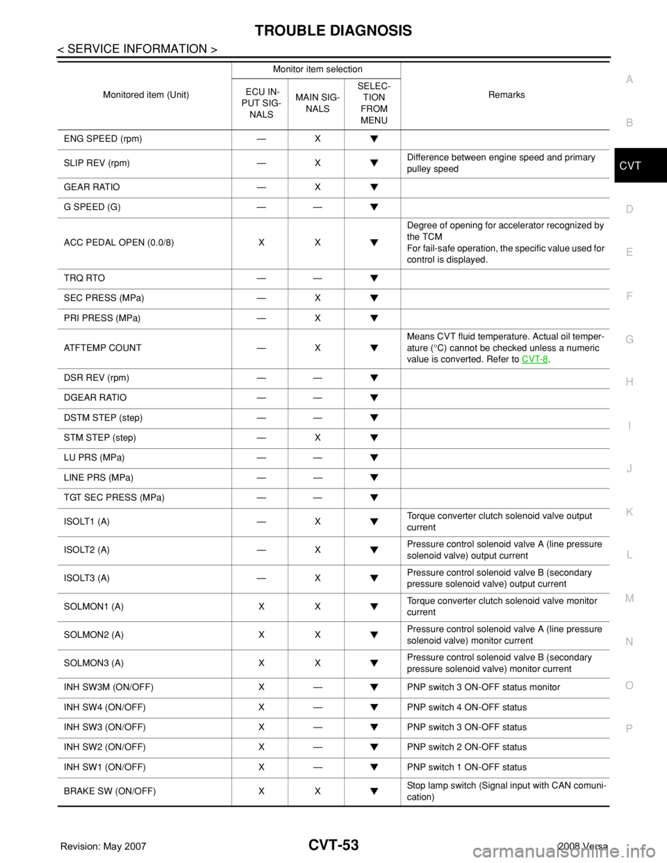
ENG SPEED (rpm) — X
SLIP REV (rpm) — XDifference between engine speed and primary
pulley speed
GEAR RATIO — X
G SPEED (G) — —
ACC PEDAL OPEN (0.0/8) X XDegree of opening for accelerator recognized by
the TCM
For fail-safe operation, the specific value used for
control is displayed.
TRQ RTO — —
SEC PRESS (MPa) — X
PRI PRESS (MPa) — X
ATFTEMP COUNT — XMeans CVT fluid temperature. Actual oil temper-
ature (°C) cannot be checked unless a numeric
value is converted. Refer to CVT-8
.
DSR REV (rpm) — —
DGEAR RATIO — —
DSTM STEP (step) — —
STM STEP (step) — X
LU PRS (MPa) — —
LINE PRS (MPa) — —
TGT SEC PRESS (MPa) — —
ISOLT1 (A) — XTorque converter clutch solenoid valve output
current
ISOLT2 (A) — XPressure control solenoid valve A (line pressure
solenoid valve) output current
ISOLT3 (A) — XPressure control solenoid valve B (secondary
pressure solenoid valve) output current
SOLMON1 (A) X XTorque converter clutch solenoid valve monitor
current
SOLMON2 (A) X XPressure control solenoid valve A (line pressure
solenoid valve) monitor current
SOLMON3 (A) X XPressure control solenoid valve B (secondary
pressure solenoid valve) monitor current
INH SW3M (ON/OFF) X — PNP switch 3 ON-OFF status monitor
INH SW4 (ON/OFF) X — PNP switch 4 ON-OFF status
INH SW3 (ON/OFF) X — PNP switch 3 ON-OFF status
INH SW2 (ON/OFF) X — PNP switch 2 ON-OFF status
INH SW1 (ON/OFF) X — PNP switch 1 ON-OFF status
BRAKE SW (ON/OFF) X XStop lamp switch (Signal input with CAN comuni-
cation) Monitored item (Unit)Monitor item selection
Remarks ECU IN-
PUT SIG-
NALSMAIN SIG-
NALSSELEC-
TION
FROM
MENU
Page 939 of 2771

CVT-100
< SERVICE INFORMATION >
DTC P0746 PRESSURE CONTROL SOLENOID A PERFORMANCE (LINE PRES-
SURE SOLENOID VALVE)
DTC P0746 PRESSURE CONTROL SOLENOID A PERFORMANCE (LINE
PRESSURE SOLENOID VALVE)
DescriptionINFOID:0000000001703553
• The pressure control solenoid valve A (line pressure solenoid valve) is included in the control valve assem-
bly.
• The pressure control solenoid valve A (line pressure solenoid valve) regulates the oil pump discharge pres-
sure to suit the driving condition in response to a signal sent from the TCM.
CONSULT-III Reference Value in Data Monitor ModeINFOID:0000000001703554
Remarks: Specification data are reference values.
On Board Diagnosis LogicINFOID:0000000001703555
• This is an OBD-II self-diagnostic item.
• Diagnostic trouble code “P0746 PRS CNT SOL/A FCTN” with CONSULT-III is detected under the following
conditions.
- Unexpected gear ratio was detected in the LOW side due to excessively low line pressure.
Possible CauseINFOID:0000000001703556
• Line pressure control system
• Output speed sensor (Secondary speed sensor)
• Input speed sensor (Primary speed sensor)
DTC Confirmation ProcedureINFOID:0000000001703557
CAUTION:
Always drive vehicle at a safe speed.
NOTE:
If “DTC Confirmation Procedure” has been previously performed, always turn ignition switch OFF and
wait at least 10 seconds before performing the next test.
After the repair, touch “ERASE” on “SELF-DIAG RESULTS” and then perform the following procedure to con-
firm the malfunction is eliminated.
WITH CONSULT-III
1. Turn ignition switch ON and select “DATA MONITOR” mode for “TRANSMISSION” with CONSULT-III.
2. Start engine and maintain the following conditions for at least 10 consecutive seconds. Test start from 0
km/h (0 MPH).
ATF TEMP SEN: 1.0 - 2.0 V
ACC PEDAL OPEN: More than 1.0/8
RANGE: “D” position
VEHICLE SPEED: 10 km/h (6 MPH) More than
Driving location: Driving the vehicle uphill (increased engine load) will help maintain the driving
conditions required for this test.
3. If DTC is detected, go to CVT-100, "
Diagnosis Procedure".
WITH GST
Follow the procedure “WITH CONSULT-III”.
Diagnosis ProcedureINFOID:0000000001703558
1.CHECK INPUT SIGNAL
With CONSULT-III
1. Start engine.
2. Select “MAIN SIGNALS” in “DATA MONITOR” mode for “TRANSMISSION” with CONSULT-III.
3. Start vehicle and read out the value of “PRI PRESS”.
Item name Condition Display value (Approx.)
PRI PRESS “N” position idle 0.4 MPa
Page 975 of 2771
CVT-136
< SERVICE INFORMATION >
DTC P1745 LINE PRESSURE CONTROL
DTC P1745 LINE PRESSURE CONTROL
DescriptionINFOID:0000000001703635
The pressure control solenoid valve A (line pressure solenoid valve) regulates the oil pump discharge pres-
sure to suit the driving condition in response to a signal sent from the TCM.
On Board Diagnosis LogicINFOID:0000000001703636
• This is not an OBD-II self-diagnostic item.
• Diagnostic trouble code “P1745 L/PRESS CONTROL” with CONSULT-III is detected when TCM detects the
unexpected line pressure.
Possible CauseINFOID:0000000001703637
TCM
DTC Confirmation ProcedureINFOID:0000000001703638
NOTE:
If “DTC Confirmation Procedure” has been previously performed, always turn ignition switch OFF and
wait at least 10 seconds before performing the next test.
After the repair, touch “ERASE” on “SELF-DIAG RESULTS” and then perform the following procedure to con-
firm the malfunction is eliminated.
WITH CONSULT-III
1. Turn ignition switch ON and select “DATA MONITOR” mode for “TRANSMISSION” with CONSULT-III.
2. Make sure that output voltage of CVT fluid temperature sensor is within the range below.
ATF TEMP SEN: 1.0 - 2.0 V
If out of range, drive the vehicle to decrease the voltage (warm up the fluid) or stop engine to
increase the voltage (cool down the fluid)
3. If DTC is detected, go to CVT-136, "
Diagnosis Procedure" .
Diagnosis ProcedureINFOID:0000000001703639
1.CHECK DTC
1. Turn ignition switch ON. (Do not start engine.)
2. Select “SELF-DIAG RESULTS” mode for “TRANSMISSION” with CONSULT-III.
3. Erase self-diagnostic results. Refer to CVT-26, "
OBD-II Diagnostic Trouble Code (DTC)".
4. Turn ignition switch OFF, and wait for 10 seconds or more.
5. Start engine.
6. Confirm self-diagnostic results again. Refer to CVT-47, "
CONSULT-III Function (TRANSMISSION)" .
Is the
“P1745 L/PRESS CONTROL” displayed?
YES >> Replace TCM. Refer to CVT-8, "Service After Replacing TCM and Transaxle Assembly" .
NO >>INSPECTION END
Page 978 of 2771
DTC P1777 STEP MOTOR - CIRCUIT
CVT-139
< SERVICE INFORMATION >
D
E
F
G
H
I
J
K
L
MA
B
CVT
N
O
P
Diagnosis ProcedureINFOID:0000000001703646
1.CHECK INPUT SIGNALS
With CONSULT-III
1. Start engine.
2. Select “SELECTION FROM MENU” in “DATA MONITOR” mode for “TRANSMISSION” with CONSULT-III.
3. Start vehicle and read out the value of “STM STEP”, “SMCOIL A”, “SMCOIL B”, “SMCOIL C”, and
“SMCOIL D”.
OK or NG
OK >> GO TO 4.
NG >> GO TO 2.
2.CHECK HARNESS BETWEEN TCM AND STEP MOTOR
1. Turn ignition switch OFF.
2. Disconnect CVT unit connector and TCM connector.
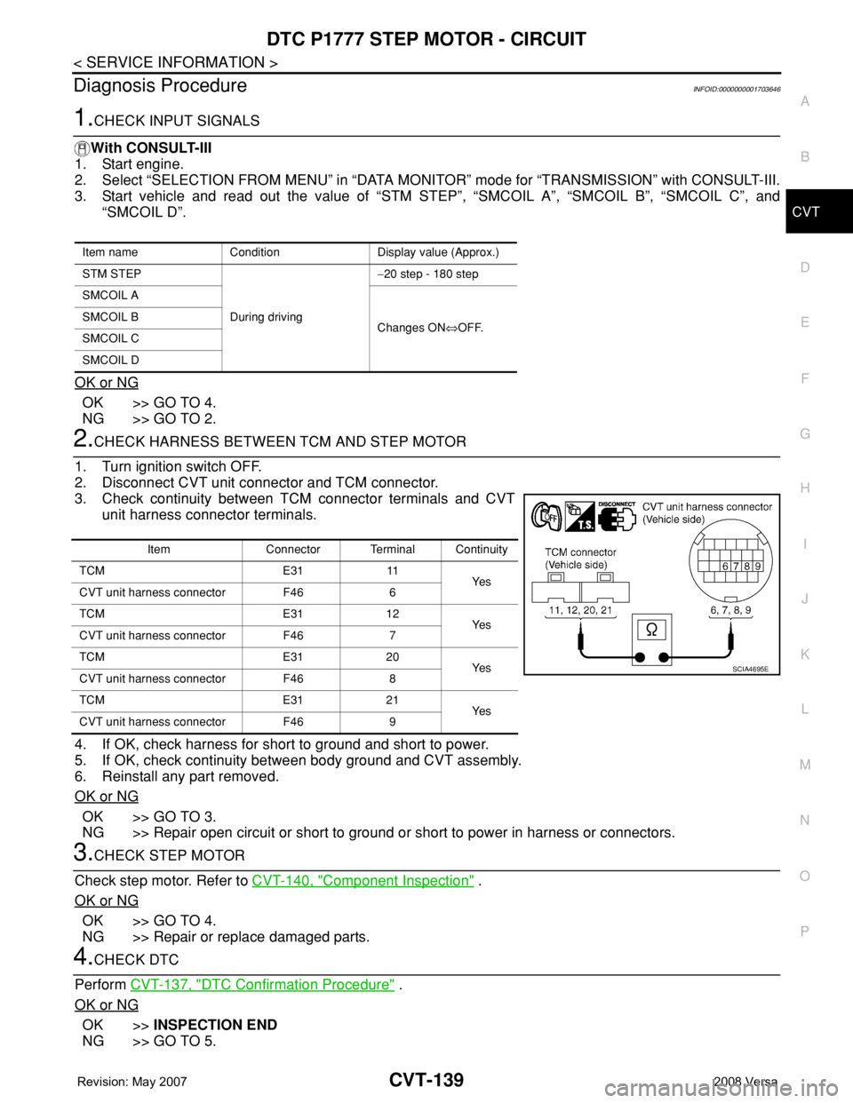
3. Check continuity between TCM connector terminals and CVT
unit harness connector terminals.
4. If OK, check harness for short to ground and short to power.
5. If OK, check continuity between body ground and CVT assembly.
6. Reinstall any part removed.
OK or NG
OK >> GO TO 3.
NG >> Repair open circuit or short to ground or short to power in harness or connectors.
3.CHECK STEP MOTOR
Check step motor. Refer to CVT-140, "
Component Inspection" .
OK or NG
OK >> GO TO 4.
NG >> Repair or replace damaged parts.
4.CHECK DTC
Perform CVT-137, "
DTC Confirmation Procedure" .
OK or NG
OK >>INSPECTION END
NG >> GO TO 5.
Item name Condition Display value (Approx.)
STM STEP
During driving−20 step - 180 step
SMCOIL A
Changes ON⇔OFF. SMCOIL B
SMCOIL C
SMCOIL D
Item Connector Terminal Continuity
TCM E31 11
Ye s
CVT unit harness connector F46 6
TCM E31 12
Ye s
CVT unit harness connector F46 7
TCM E31 20
Ye s
CVT unit harness connector F46 8
TCM E31 21
Ye s
CVT unit harness connector F46 9
SCIA4695E
Page 1016 of 2771
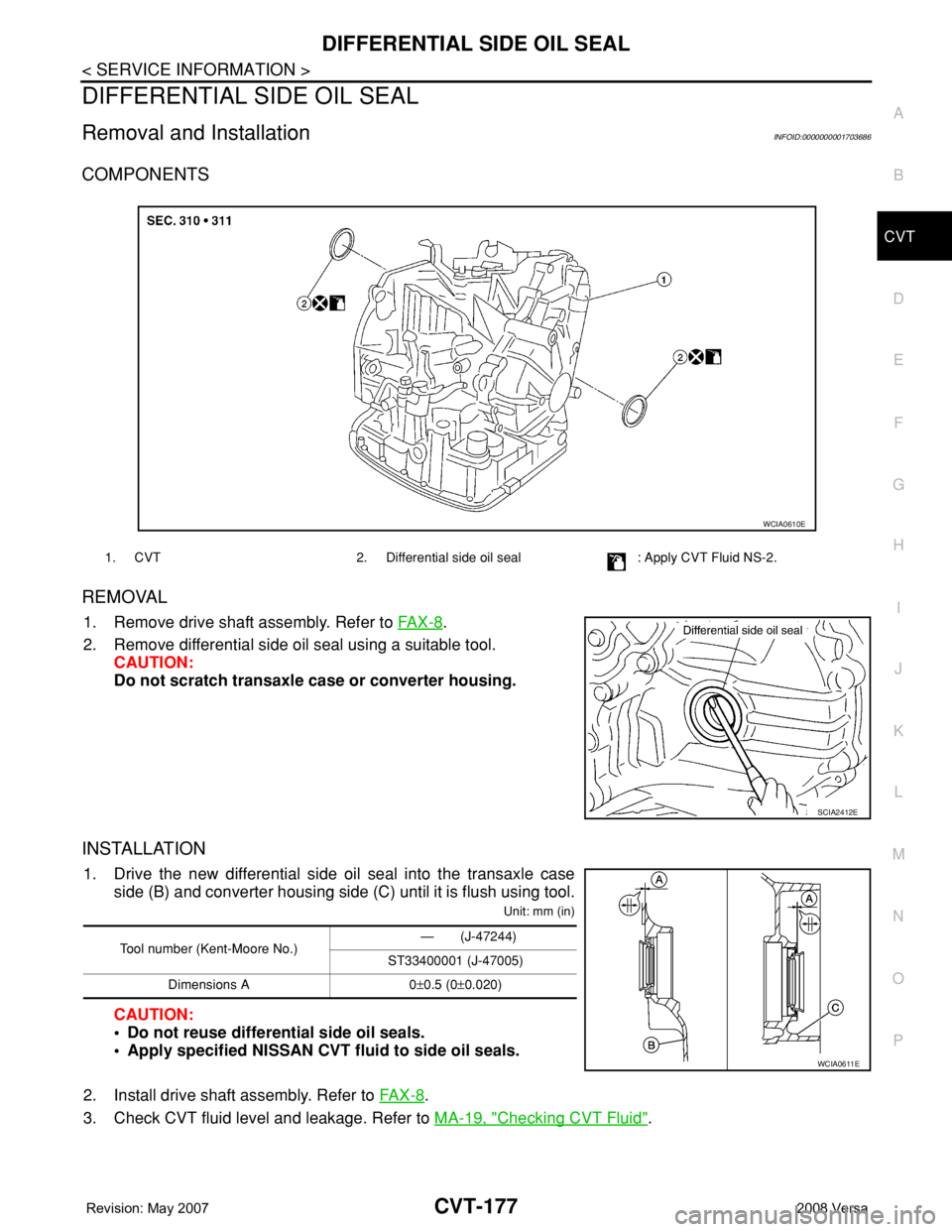
DIFFERENTIAL SIDE OIL SEAL
CVT-177
< SERVICE INFORMATION >
D
E
F
G
H
I
J
K
L
MA
B
CVT
N
O
P
DIFFERENTIAL SIDE OIL SEAL
Removal and InstallationINFOID:0000000001703686
COMPONENTS
REMOVAL
1. Remove drive shaft assembly. Refer to FA X - 8.
2. Remove differential side oil seal using a suitable tool.
CAUTION:
Do not scratch transaxle case or converter housing.
INSTALLATION
1. Drive the new differential side oil seal into the transaxle case
side (B) and converter housing side (C) until it is flush using tool.
Unit: mm (in)
CAUTION:
• Do not reuse differential side oil seals.
• Apply specified NISSAN CVT fluid to side oil seals.
2. Install drive shaft assembly. Refer to FA X - 8
.
3. Check CVT fluid level and leakage. Refer to MA-19, "
Checking CVT Fluid".
1. CVT 2. Differential side oil seal : Apply CVT Fluid NS-2.
WCIA0610E
SCIA2412E
Tool number (Kent-Moore No.)— (J-47244)
ST33400001 (J-47005)
Dimensions A 0±0.5 (0±0.020)
WCIA0611E
Page 1018 of 2771
TRANSAXLE ASSEMBLY
CVT-179
< SERVICE INFORMATION >
D
E
F
G
H
I
J
K
L
MA
B
CVT
N
O
P
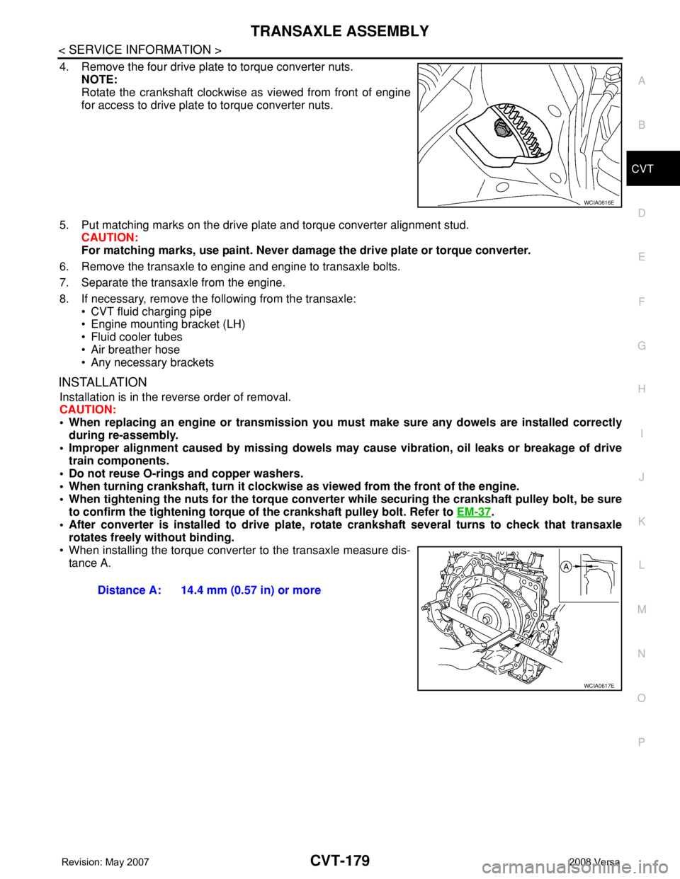
4. Remove the four drive plate to torque converter nuts.
NOTE:
Rotate the crankshaft clockwise as viewed from front of engine
for access to drive plate to torque converter nuts.
5. Put matching marks on the drive plate and torque converter alignment stud.
CAUTION:
For matching marks, use paint. Never damage the drive plate or torque converter.
6. Remove the transaxle to engine and engine to transaxle bolts.
7. Separate the transaxle from the engine.
8. If necessary, remove the following from the transaxle:
• CVT fluid charging pipe
• Engine mounting bracket (LH)
• Fluid cooler tubes
• Air breather hose
• Any necessary brackets
INSTALLATION
Installation is in the reverse order of removal.
CAUTION:
• When replacing an engine or transmission you must make sure any dowels are installed correctly
during re-assembly.
• Improper alignment caused by missing dowels may cause vibration, oil leaks or breakage of drive
train components.
• Do not reuse O-rings and copper washers.
• When turning crankshaft, turn it clockwise as viewed from the front of the engine.
• When tightening the nuts for the torque converter while securing the crankshaft pulley bolt, be sure
to confirm the tightening torque of the crankshaft pulley bolt. Refer to EM-37
.
• After converter is installed to drive plate, rotate crankshaft several turns to check that transaxle
rotates freely without binding.
• When installing the torque converter to the transaxle measure dis-
tance A.
WCIA0616E
Distance A: 14.4 mm (0.57 in) or more
WCIA0617E
Page 1035 of 2771

DI-14
< SERVICE INFORMATION >
COMBINATION METERS
NOTE:
Some items are not available due to vehicle specification.
*: The monitor will indicate “OFF” even though the brake warning lamp is on if either of the following conditions exist.
• The parking brake is engaged
• The brake fluid level is low
Trouble DiagnosisINFOID:0000000001704499
HOW TO PERFORM TROUBLE DIAGNOSIS
1. Confirm the symptom or customer complaint.
2. Perform preliminary check. Refer to "PRELIMINARY CHECK" .
3. According to the symptom chart, repair or replace the cause of the malfunction. Refer to DI-15, "
Symptom
Chart" .
4. Does the meter operate normally? If so, GO TO 5. If not, GO TO 2.
5. Inspection End.
PRELIMINARY CHECK
1.CHECK SELF-DIAGNOSIS OPERATION OF COMBINATION METER
Perform self-diagnosis of combination meter. Refer to DI-11, "
Self-Diagnosis Mode of Combination Meter" .
Does self
-diagnosis mode operate?
YES >> GO TO 2.
TURN IND [ON/OFF] X Indicates [ON/OFF] condition of turn indicator.
OIL W/L [ON/OFF] X Indicates [ON/OFF] condition of oil pressure warning lamp.
ABS W/L [ON/OFF] X Indicates [ON/OFF] condition of ABS warning lamp.
BRAKE W/L [ON/OFF] X Indicates [ON/OFF] condition of brake warning lamp.*
KEY G W/L [ON/OFF] X Indicates [ON/OFF] condition of KEY warning lamp (green).
KEY R W/L [ON/OFF] X Indicates [ON/OFF] condition of KEY warning lamp (red).
KEY KNOB W/L [ON/OFF] X Indicates [ON/OFF] condition of LOCK warning lamp.
PNP P SW [ON/OFF] X X Indicates [ON/OFF] condition of inhibitor P switch.
PNP N SW [ON/OFF] X X Indicates [ON/OFF] condition of inhibitor N switch.
O/D OFF SW [ON/OFF] X Indicates [ON/OFF] condition of O/D OFF switch.
BRAKE SW [ON/OFF] X Indicates [ON/OFF] condition of parking brake switch.
P RANGE IND [ON/OFF] X XIndicates [ON/OFF] condition of A/T or CVT shift P range indi-
cator.
R RANGE IND [ON/OFF] X XIndicates [ON/OFF] condition of A/T or CVT shift R range indi-
cator.
N RANGE IND [ON/OFF] X XIndicates [ON/OFF] condition of A/T or CVT shift N range indi-
cator.
D RANGE IND [ON/OFF] X XIndicates [ON/OFF] condition of A/T or CVT shift D range indi-
cator.
2 RANGE IND [ON/OFF] X X Indicates [ON/OFF] condition of A/T shift 2 range indicator.
L RANGE IND [ON/OFF] X X Indicates [ON/OFF] condition of CVT shift L range indicator.
1 RANGE IND [ON/OFF] X X Indicates [ON/OFF] condition of A/T shift 1 range indicator.
CRUISE IND [ON/OFF] X Indicates [ON/OFF] condition of CRUISE indicator.
SET IND [ON/OFF] X Indicates [ON/OFF] condition of SET indicator.
O/D OFF W/L [ON/OFF] X Indicates [ON/OFF] condition of O/D OFF indicator lamp.
e-4WD W/L [ON/OFF] X This item is not used for this model. “OFF” is always displayed.
EPS W/L [ON/OFF] X Indicates [ON/OFF] condition of EPS warning lamp. Display item [Unit]MAIN
SIGNALSSELECTION
FROM MENUContents