2008 NISSAN LATIO ABS
[x] Cancel search: ABSPage 893 of 2771

CVT-54
< SERVICE INFORMATION >
TROUBLE DIAGNOSIS
FULL SW (ON/OFF) X X
Signal input with CAN communications
IDLE SW (ON/OFF) X X
SPORT MODE SW (ON/OFF) X XOverdrive control switch (Signal input with CAN
comunication)
STRDWNSW (ON/OFF) X —
Not mounted but displayed. STRUPSW (ON/OFF) X —
DOWNLVR (ON/OFF) X —
UPLVR (ON/OFF) X —
NONMMODE (ON/OFF) X —
MMODE (ON/OFF) X —
INDLRNG (ON/OFF) — — “L” position indicator output
INDDRNG (ON/OFF) — — “D” position indicator output
INDNRNG (ON/OFF) — — “N” position indicator output
INDRRNG (ON/OFF) — — “R” position indicator output
INDPRNG (ON/OFF) — — “P” position indicator output
CVT LAMP (ON/OFF) — —
SPORT MODE IND (ON/OFF) — —
MMODE IND (ON/OFF) — — Not mounted but displayed.
SMCOIL D (ON/OFF) — — Step motor coil “D” energizing status
SMCOIL C (ON/OFF) — — Step motor coil “C” energizing status
SMCOIL B (ON/OFF) — — Step motor coil “B” energizing status
SMCOIL A (ON/OFF) — — Step motor coil “A” energizing status
LUSEL SOL OUT (ON/OFF) — —
REV LAMP (ON/OFF) — X
STRTR RLY OUT (ON/OFF) — — Starter relay
LUSEL SOL MON (ON/OFF) — —
STRTR RLY MON (ON/OFF) — — Starter relay
VDC ON (ON/OFF) X —
Not mounted but displayed.
TCS ON (ON/OFF) X —
ABS ON (ON/OFF) X —
ACC ON (ON/OFF) X — Not mounted but displayed.
RANGE — XIndicates position is recognized by TCM. Indi-
cates a specific value required for control when
fail-safe function is activated.
M GEAR POS — X
Voltage (V) — —Displays the value measured by the voltage
probe. Monitored item (Unit)Monitor item selection
Remarks ECU IN-
PUT SIG-
NALSMAIN SIG-
NALSSELEC-
TION
FROM
MENU
Page 966 of 2771
DTC P1722 ESTM VEHICLE SPEED SIGNAL
CVT-127
< SERVICE INFORMATION >
D
E
F
G
H
I
J
K
L
MA
B
CVT
N
O
P
DTC P1722 ESTM VEHICLE SPEED SIGNAL
DescriptionINFOID:0000000001703611
The vehicle speed signal is transmitted from ABS actuator and electric unit (control unit) to TCM by CAN com-
munication line.
CONSULT-III Reference Value in Data Monitor ModeINFOID:0000000001703612
Remarks: Specification data are reference values.
On Board Diagnosis LogicINFOID:0000000001703613
• This is not an OBD-II self-diagnostic item.
• Diagnostic trouble code “P1722 ESTM VEH SPD SIG” with CONSULT-III is detected when TCM does not
receive the proper vehicle speed signal (input by CAN communication) from ABS actuator and electric unit
(control unit).
Possible CauseINFOID:0000000001703614
• Harness or connectors
(Sensor circuit is open or shorted.)
• ABS actuator and electric unit (control unit)
DTC Confirmation ProcedureINFOID:0000000001703615
CAUTION:
Always drive vehicle at a safe speed.
NOTE:
If “DTC Confirmation Procedure” has been previously performed, always turn ignition switch OFF and
wait at least 10 seconds before performing the next test.
After the repair, touch “ERASE” on “SELF-DIAG RESULTS” and then perform the following procedure to con-
firm the malfunction is eliminated.
WITH CONSULT-III
1. Turn ignition switch ON. (Do not start engine.)
2. Select “DATA MONITOR” mode for “TRANSMISSION” with CONSULT-III.
3. Start engine and maintain the following conditions for at least 5 consecutive seconds.
ACC PEDAL OPEN: 1.0/8 or less
VEHICLE SPEED SE: 30 km/h (17 MPH) or more
4. If DTC is detected, go to CVT-127, "
Diagnosis Procedure".
Diagnosis ProcedureINFOID:0000000001703616
1.CHECK CAN COMMUNICATION LINE
Perform the self-diagnosis check. Refer to CVT-47, "
CONSULT-III Function (TRANSMISSION)".
Is any malfunction of the
“U1000 CAN COMM CIRCUIT” indicated?
YES >> Check CAN communication line. Refer to CVT-56.
NO >> GO TO 2.
2.CHECK ABS ACTUATOR AND ELECTRIC UNIT (CONTROL UNIT)
Perform ABS actuator and electric unit (control unit) self-diagnosis check. Refer to BRC-18, "
CONSULT-III
Function (ABS)".
OK or NG
OK >> GO TO 3.
NG >> Repair or replace damaged parts.
Item name Condition Display value
ESTM VSP SIG
During driving Approximately matches the speedometer reading.
VEHICLE SPEED
Page 1008 of 2771
SHIFT CONTROL SYSTEM
CVT-169
< SERVICE INFORMATION >
D
E
F
G
H
I
J
K
L
MA
B
CVT
N
O
P
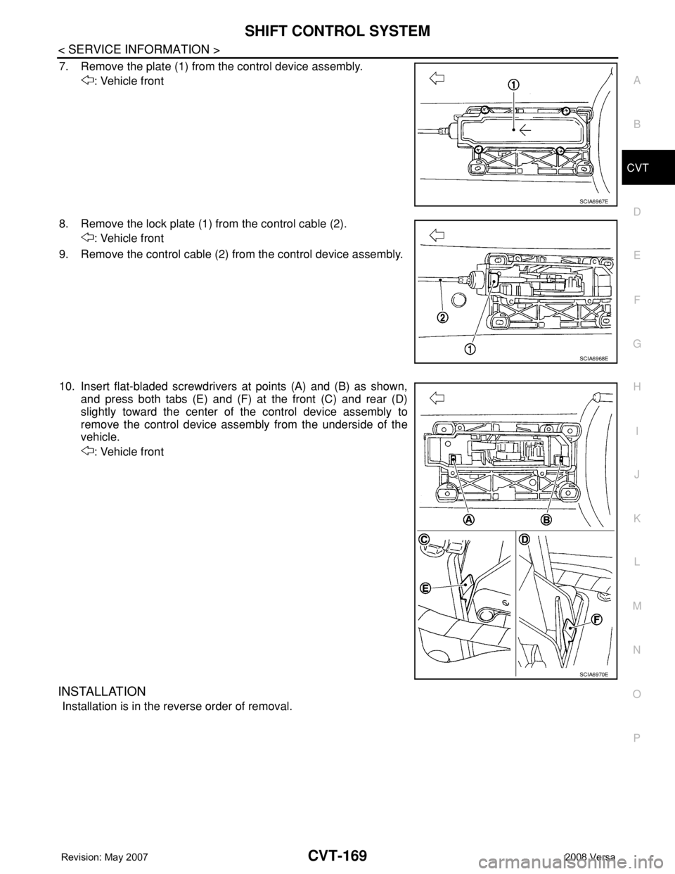
7. Remove the plate (1) from the control device assembly.
: Vehicle front
8. Remove the lock plate (1) from the control cable (2).
: Vehicle front
9. Remove the control cable (2) from the control device assembly.
10. Insert flat-bladed screwdrivers at points (A) and (B) as shown,
and press both tabs (E) and (F) at the front (C) and rear (D)
slightly toward the center of the control device assembly to
remove the control device assembly from the underside of the
vehicle.
: Vehicle front
INSTALLATION
Installation is in the reverse order of removal.
SCIA6967E
SCIA6968E
SCIA6970E
Page 1009 of 2771
CVT-170
< SERVICE INFORMATION >
SHIFT CONTROL SYSTEM
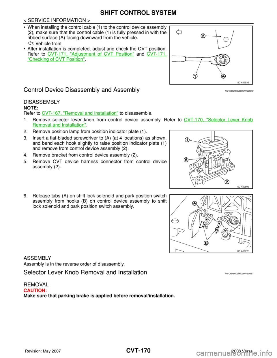
• When installing the control cable (1) to the control device assembly
(2), make sure that the control cable (1) is fully pressed in with the
ribbed surface (A) facing downward from the vehicle.
: Vehicle front
• After installation is completed, adjust and check the CVT position.
Refer to CVT-171, "
Adjustment of CVT Position" and CVT-171,
"Checking of CVT Position".
Control Device Disassembly and AssemblyINFOID:0000000001703680
DISASSEMBLY
NOTE:
Refer to CVT-167, "
Removal and Installation" to disassemble.
1. Remove selector lever knob from control device assembly. Refer to CVT-170, "
Selector Lever Knob
Removal and Installation".
2. Remove position lamp from position indicator plate (1).
3. Insert a flat-bladed screwdriver to (A) (at 4 locations) as shown,
and bend each hook slightly to raise position indicator plate (1)
and remove from control device assembly (2).
4. Remove bracket from control device assembly (2).
5. Remove CVT device harness connector from control device
assembly (2).
6. Release tabs (A) on shift lock solenoid and park position switch
assembly from hooks (B) on control device assembly to shift
lock solenoid and park position switch assembly.
ASSEMBLY
Assembly is in the reverse order of disassembly.
Selector Lever Knob Removal and InstallationINFOID:0000000001703681
REMOVAL
CAUTION:
Make sure that parking brake is applied before removal/installation.
SCIA6253E
SCIA6969E
SCIA6977E
Page 1013 of 2771
CVT-174
< SERVICE INFORMATION >
KEY INTERLOCK CABLE
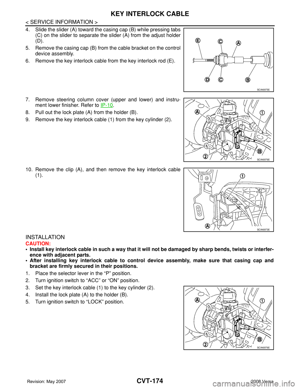
4. Slide the slider (A) toward the casing cap (B) while pressing tabs
(C) on the slider to separate the slider (A) from the adjust holder
(D).
5. Remove the casing cap (B) from the cable bracket on the control
device assembly.
6. Remove the key interlock cable from the key interlock rod (E).
7. Remove steering column cover (upper and lower) and instru-
ment lower finisher. Refer to IP-10
.
8. Pull out the lock plate (A) from the holder (B).
9. Remove the key interlock cable (1) from the key cylinder (2).
10. Remove the clip (A), and then remove the key interlock cable
(1).
INSTALLATION
CAUTION:
• Install key interlock cable in such a way that it will not be damaged by sharp bends, twists or interfer-
ence with adjacent parts.
• After installing key interlock cable to control device assembly, make sure that casing cap and
bracket are firmly secured in their positions.
1. Place the selector lever in the “P” position.
2. Turn ignition switch to “ACC” or “ON” position.
3. Set the key interlock cable (1) to the key cylinder (2).
4. Install the lock plate (A) to the holder (B).
5. Turn ignition switch to “LOCK” position.
SCIA6975E
SCIA6976E
SCIA6973E
SCIA6976E
Page 1014 of 2771
KEY INTERLOCK CABLE
CVT-175
< SERVICE INFORMATION >
D
E
F
G
H
I
J
K
L
MA
B
CVT
N
O
P
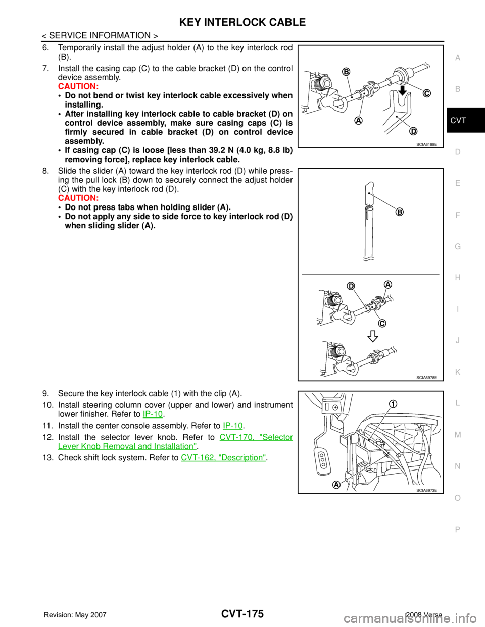
6. Temporarily install the adjust holder (A) to the key interlock rod
(B).
7. Install the casing cap (C) to the cable bracket (D) on the control
device assembly.
CAUTION:
• Do not bend or twist key interlock cable excessively when
installing.
• After installing key interlock cable to cable bracket (D) on
control device assembly, make sure casing caps (C) is
firmly secured in cable bracket (D) on control device
assembly.
• If casing cap (C) is loose [less than 39.2 N (4.0 kg, 8.8 lb)
removing force], replace key interlock cable.
8. Slide the slider (A) toward the key interlock rod (D) while press-
ing the pull lock (B) down to securely connect the adjust holder
(C) with the key interlock rod (D).
CAUTION:
• Do not press tabs when holding slider (A).
• Do not apply any side to side force to key interlock rod (D)
when sliding slider (A).
9. Secure the key interlock cable (1) with the clip (A).
10. Install steering column cover (upper and lower) and instrument
lower finisher. Refer to IP-10
.
11. Install the center console assembly. Refer to IP-10
.
12. Install the selector lever knob. Refer to CVT-170, "
Selector
Lever Knob Removal and Installation".
13. Check shift lock system. Refer to CVT-162, "
Description".
SCIA6188E
SCIA6978E
SCIA6973E
Page 1025 of 2771
DI-4
< SERVICE INFORMATION >
COMBINATION METERS
COMBINATION METERS
Component Parts and Harness Connector LocationINFOID:0000000001704490
System DescriptionINFOID:0000000001704491
UNIFIED METER CONTROL UNIT
• Speedometer, odo/trip meter, tachometer and fuel gauge are controlled by the unified meter control unit,
which is built into the combination meter.
• Warning and indicator lamps are controlled by signals drawn from the CAN communication system, BCM
(body control module), and components connected directly to the combination meter.
• Odo/trip meter and A/T indicator (with A/T) or CVT indicator (with CVT) segments can be checked in self-
diagnosis mode.
• Meters/gauges can be checked in self-diagnosis mode.
POWER SUPPLY AND GROUND CIRCUIT
Power is supplied at all times
• through 10A fuse [No. 13, located in the fuse block (J/B)]
• to combination meter terminal 27.
With the ignition switch in the ON or START position, power is supplied
• through 10A fuse [No. 14, located in the fuse block (J/B)]
• to combination meter terminal 28.
Ground is supplied
• to combination meter terminals 21, 22 and 23
• through grounds M57 and M61.
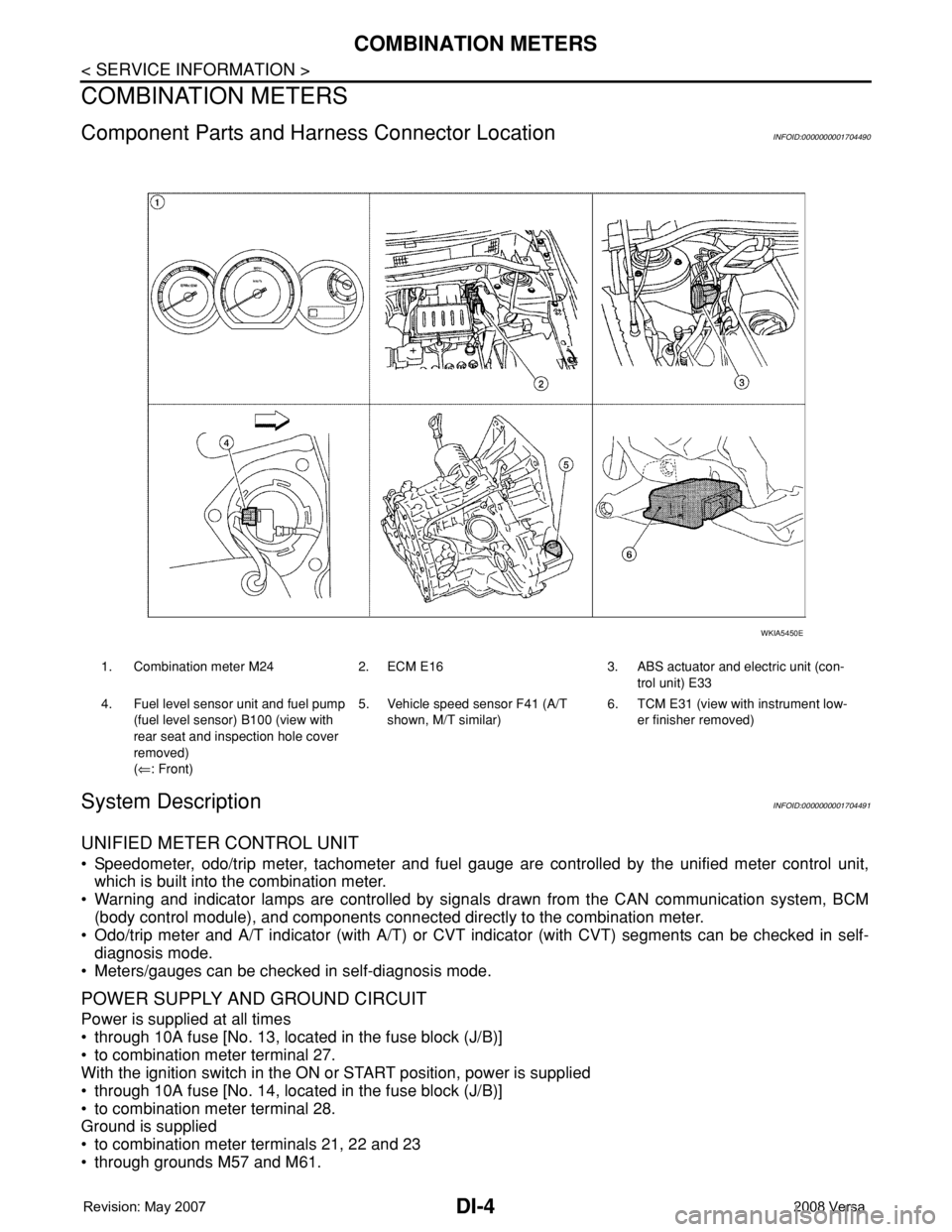
1. Combination meter M24 2. ECM E16 3. ABS actuator and electric unit (con-
trol unit) E33
4. Fuel level sensor unit and fuel pump
(fuel level sensor) B100 (view with
rear seat and inspection hole cover
removed)
(⇐: Front)5. Vehicle speed sensor F41 (A/T
shown, M/T similar)6. TCM E31 (view with instrument low-
er finisher removed)
WKIA5450E
Page 1026 of 2771
COMBINATION METERS
DI-5
< SERVICE INFORMATION >
C
D
E
F
G
H
I
J
L
MA
B
DI
N
O
P
SPEEDOMETER
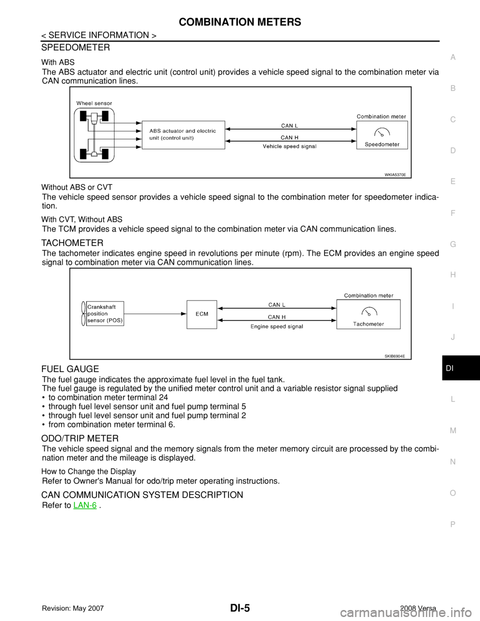
With ABS
The ABS actuator and electric unit (control unit) provides a vehicle speed signal to the combination meter via
CAN communication lines.
Without ABS or CVT
The vehicle speed sensor provides a vehicle speed signal to the combination meter for speedometer indica-
tion.
With CVT, Without ABS
The TCM provides a vehicle speed signal to the combination meter via CAN communication lines.
TACHOMETER
The tachometer indicates engine speed in revolutions per minute (rpm). The ECM provides an engine speed
signal to combination meter via CAN communication lines.
FUEL GAUGE
The fuel gauge indicates the approximate fuel level in the fuel tank.
The fuel gauge is regulated by the unified meter control unit and a variable resistor signal supplied
• to combination meter terminal 24
• through fuel level sensor unit and fuel pump terminal 5
• through fuel level sensor unit and fuel pump terminal 2
• from combination meter terminal 6.
ODO/TRIP METER
The vehicle speed signal and the memory signals from the meter memory circuit are processed by the combi-
nation meter and the mileage is displayed.
How to Change the Display
Refer to Owner's Manual for odo/trip meter operating instructions.
CAN COMMUNICATION SYSTEM DESCRIPTION
Refer to LAN-6 .
WKIA5370E
SKIB6904E