2008 NISSAN LATIO ABS
[x] Cancel search: ABSPage 800 of 2771
![NISSAN LATIO 2008 Service Repair Manual ACTUATOR AND ELECTRIC UNIT (ASSEMBLY)
BRC-35
< SERVICE INFORMATION >[ABS]
C
D
E
G
H
I
J
K
L
MA
B
BRC
N
O
P
ACTUATOR AND ELECTRIC UNIT (ASSEMBLY)
Removal and InstallationINFOID:0000000001703852
CAUTION NISSAN LATIO 2008 Service Repair Manual ACTUATOR AND ELECTRIC UNIT (ASSEMBLY)
BRC-35
< SERVICE INFORMATION >[ABS]
C
D
E
G
H
I
J
K
L
MA
B
BRC
N
O
P
ACTUATOR AND ELECTRIC UNIT (ASSEMBLY)
Removal and InstallationINFOID:0000000001703852
CAUTION](/manual-img/5/57360/w960_57360-799.png)
ACTUATOR AND ELECTRIC UNIT (ASSEMBLY)
BRC-35
< SERVICE INFORMATION >[ABS]
C
D
E
G
H
I
J
K
L
MA
B
BRC
N
O
P
ACTUATOR AND ELECTRIC UNIT (ASSEMBLY)
Removal and InstallationINFOID:0000000001703852
CAUTION:
• Before servicing, disconnect battery cables.
• To remove brake tube, use flare nut wrench to prevent flare nuts and brake tube from being dam-
aged. To install, use flare nut torque wrench, tighten flare nut to the specified torque. Refer to BR-10,
"Hydraulic Circuit" .
• Do not apply excessive impact to ABS actuator and electric unit (control unit), such as dropping it.
• Do not remove and install actuator by holding harness.
• After work is completed, bleed air from brake tube and hose. Refer to BR-8, "
Bleeding Brake Sys-
tem" .
REMOVAL
1. Disconnect ABS actuator and electric unit (control unit) connector.
2. Loosen brake tube flare nuts, then remove brake tubes from ABS actuator and electric unit (control unit).
3. Remove brake booster hose from engine. Refer to BR-21, "
Removal and Installation" .
4. Remove ABS actuator and electric unit (control unit) bracket mounting bolts.
5. Remove ABS actuator and electric unit (control unit) from vehicle.
INSTALLATION
1. To front right 2. To rear left 3. To rear right
4. To front left 5. From master cylinder primary side 6. From master cylinder secondary
side
7. ABS actuator and electric unit (con-
trol unit)8. Harness connector : Front
Refer to GI section for symbol marks in the figure.
WFIA0506E
Page 801 of 2771
![NISSAN LATIO 2008 Service Repair Manual BRC-36
< SERVICE INFORMATION >[ABS]
ACTUATOR AND ELECTRIC UNIT (ASSEMBLY)
Installation is the reverse order of removal.
CAUTION:
After installing harness connector in the ABS actuator and electric uni NISSAN LATIO 2008 Service Repair Manual BRC-36
< SERVICE INFORMATION >[ABS]
ACTUATOR AND ELECTRIC UNIT (ASSEMBLY)
Installation is the reverse order of removal.
CAUTION:
After installing harness connector in the ABS actuator and electric uni](/manual-img/5/57360/w960_57360-800.png)
BRC-36
< SERVICE INFORMATION >[ABS]
ACTUATOR AND ELECTRIC UNIT (ASSEMBLY)
Installation is the reverse order of removal.
CAUTION:
After installing harness connector in the ABS actuator and electric unit (control unit), make sure con-
nector is securely locked.
Page 805 of 2771

CL-4
< SERVICE INFORMATION >
NOISE, VIBRATION AND HARSHNESS (NVH) TROUBLESHOOTING
NOISE, VIBRATION AND HARSHNESS (NVH) TROUBLESHOOTING
NVH Troubleshooting ChartINFOID:0000000001703116
Use the chart below to help you find the cause of the symptom. The numbers indicate the order of the inspec-
tion. If necessary, repair or replace these parts.
Reference pageCL-5CL-8EM-72CL-11CL-13EM-93
SUSPECTED PARTS (Possible cause)
CLUTCH PEDAL (Inspection and adjustment)
CLUTCH LINE (Air in line)
ENGINE MOUNTING (Loose)
CSC (Concentric slave cylinder) (Worn, dirty or damaged)
CLUTCH DISC (Out of true)
CLUTCH DISC (Runout is excessive)
CLUTCH DISC (Lining broken)
CLUTCH DISC (Dirty or burned)
CLUTCH DISC (Oily)
CLUTCH DISC (Worn out)
CLUTCH DISC (Hardened)
CLUTCH DISC (Lack of spline grease)
DIAPHRAGM SPRING (Damaged)
DIAPHRAGM SPRING (Out of tip alignment)
PRESSURE PLATE (Distortion)
FLYWHEEL (Distortion)
SymptomClutch grabs/chatters 1 2 2 2 2 2
Clutch pedal spongy 1
Clutch noisy 1
Clutch slips 1 2 2 3 4 5
Clutch does not disengage 12 55555 5667
Page 844 of 2771

INDEX FOR DTC
CVT-5
< SERVICE INFORMATION >
D
E
F
G
H
I
J
K
L
MA
B
CVT
N
O
P
SERVICE INFORMATION
INDEX FOR DTC
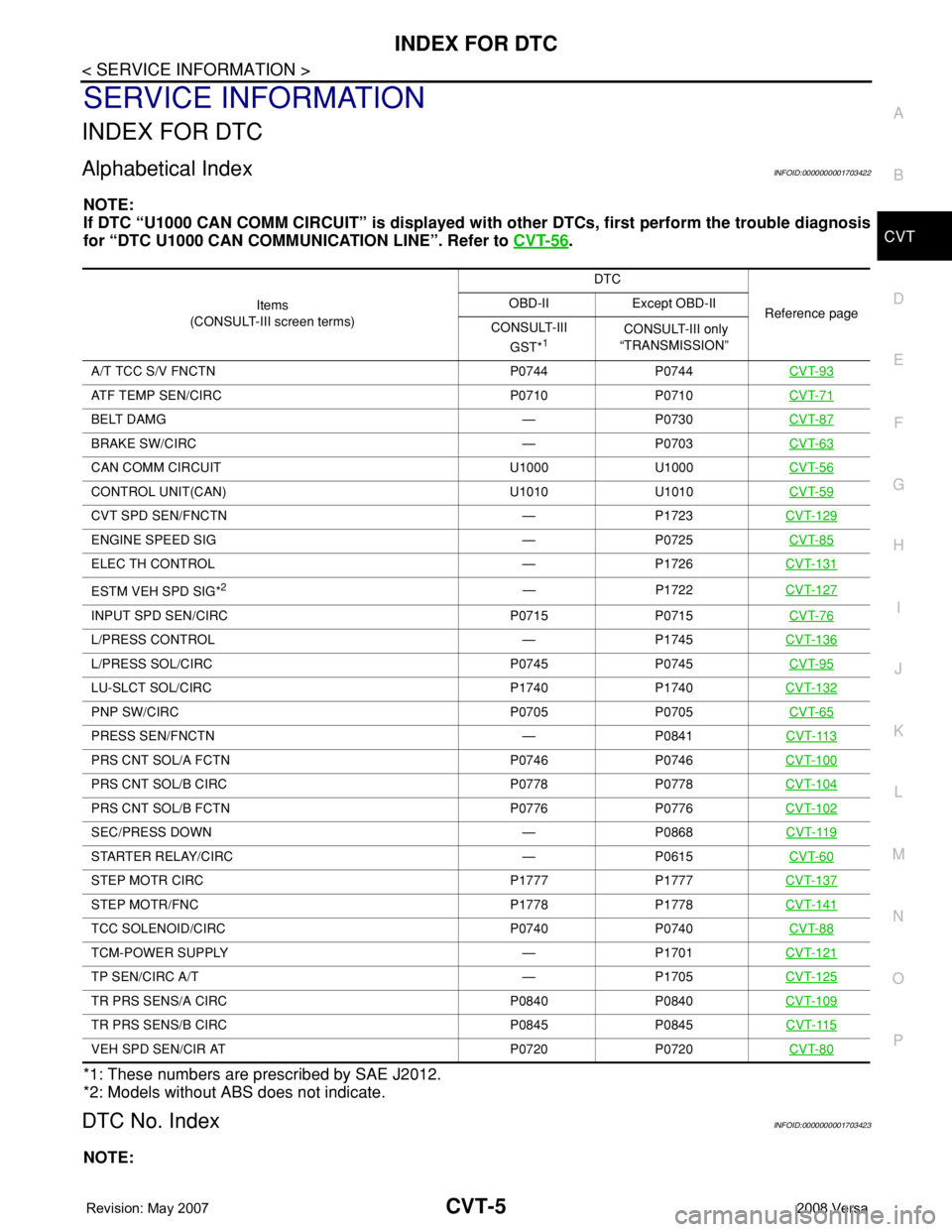
Alphabetical IndexINFOID:0000000001703422
NOTE:
If DTC “U1000 CAN COMM CIRCUIT” is displayed with other DTCs, first perform the trouble diagnosis
for “DTC U1000 CAN COMMUNICATION LINE”. Refer to CVT-56
.
*1: These numbers are prescribed by SAE J2012.
*2: Models without ABS does not indicate.
DTC No. IndexINFOID:0000000001703423
NOTE:
Items
(CONSULT-III screen terms) DTC
Reference page OBD-II Except OBD-II
CONSULT-III
GST*
1 CONSULT-III only
“TRANSMISSION”
A/T TCC S/V FNCTN P0744 P0744 CVT-93
ATF TEMP SEN/CIRC P0710 P0710CVT-71
BELT DAMG — P0730CVT-87
BRAKE SW/CIRC — P0703CVT-63
CAN COMM CIRCUIT U1000 U1000CVT-56
CONTROL UNIT(CAN) U1010 U1010CVT-59
CVT SPD SEN/FNCTN — P1723CVT-129
ENGINE SPEED SIG — P0725CVT-85
ELEC TH CONTROL — P1726CVT-131
ESTM VEH SPD SIG*2— P1722CVT-127
INPUT SPD SEN/CIRC P0715 P0715CVT-76
L/PRESS CONTROL — P1745CVT-136
L/PRESS SOL/CIRC P0745 P0745CVT-95
LU-SLCT SOL/CIRC P1740 P1740CVT-132
PNP SW/CIRC P0705 P0705CVT-65
PRESS SEN/FNCTN — P0841CVT-113
PRS CNT SOL/A FCTN P0746 P0746CVT-100
PRS CNT SOL/B CIRC P0778 P0778CVT-104
PRS CNT SOL/B FCTN P0776 P0776CVT-102
SEC/PRESS DOWN — P0868CVT-119
STARTER RELAY/CIRC — P0615CVT-60
STEP MOTR CIRC P1777 P1777CVT-137
STEP MOTR/FNC P1778 P1778CVT-141
TCC SOLENOID/CIRC P0740 P0740CVT-88
TCM-POWER SUPPLY — P1701CVT-121
TP SEN/CIRC A/T — P1705CVT-125
TR PRS SENS/A CIRC P0840 P0840CVT-109
TR PRS SENS/B CIRC P0845 P0845CVT-115
VEH SPD SEN/CIR AT P0720 P0720CVT-80
Page 845 of 2771

CVT-6
< SERVICE INFORMATION >
INDEX FOR DTC
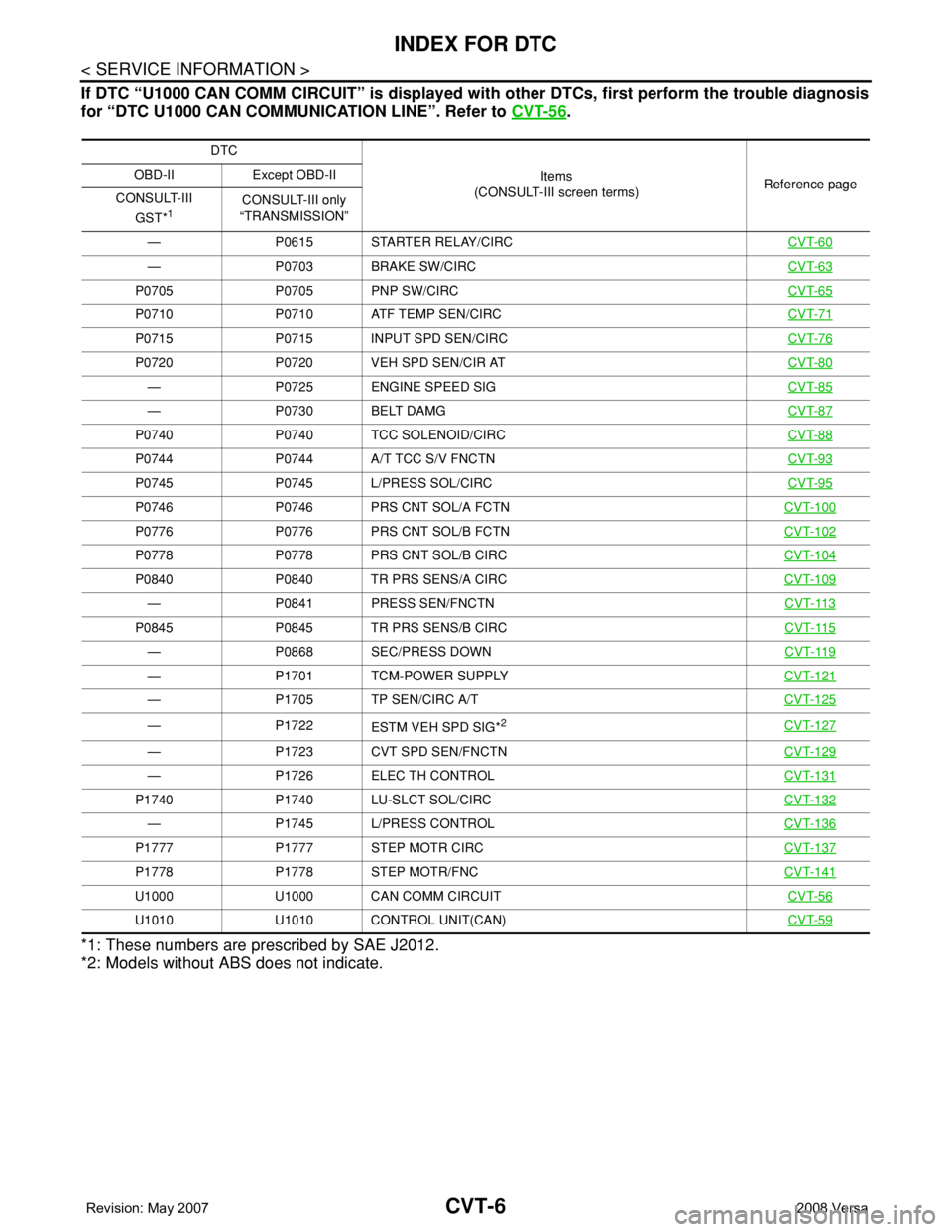
If DTC “U1000 CAN COMM CIRCUIT” is displayed with other DTCs, first perform the trouble diagnosis
for “DTC U1000 CAN COMMUNICATION LINE”. Refer to CVT-56
.
*1: These numbers are prescribed by SAE J2012.
*2: Models without ABS does not indicate.
DTC
Items
(CONSULT-III screen terms)Reference page OBD-II Except OBD-II
CONSULT-III
GST*
1CONSULT-III only
“TRANSMISSION”
— P0615 STARTER RELAY/CIRCCVT-60
— P0703 BRAKE SW/CIRCCVT-63
P0705 P0705 PNP SW/CIRCCVT-65
P0710 P0710 ATF TEMP SEN/CIRCCVT-71
P0715 P0715 INPUT SPD SEN/CIRCCVT-76
P0720 P0720 VEH SPD SEN/CIR ATCVT-80
— P0725 ENGINE SPEED SIGCVT-85
— P0730 BELT DAMGCVT-87
P0740 P0740 TCC SOLENOID/CIRCCVT-88
P0744 P0744 A/T TCC S/V FNCTNCVT-93
P0745 P0745 L/PRESS SOL/CIRCCVT-95
P0746 P0746 PRS CNT SOL/A FCTNCVT-100
P0776 P0776 PRS CNT SOL/B FCTNCVT-102
P0778 P0778 PRS CNT SOL/B CIRCCVT-104
P0840 P0840 TR PRS SENS/A CIRCCVT-109
— P0841 PRESS SEN/FNCTNCVT-113
P0845 P0845 TR PRS SENS/B CIRCCVT-115
— P0868 SEC/PRESS DOWNCVT-119
— P1701 TCM-POWER SUPPLYCVT-121
— P1705 TP SEN/CIRC A/TCVT-125
— P1722
ESTM VEH SPD SIG*2CVT-127
— P1723 CVT SPD SEN/FNCTNCVT-129
— P1726 ELEC TH CONTROLCVT-131
P1740 P1740 LU-SLCT SOL/CIRCCVT-132
— P1745 L/PRESS CONTROLCVT-136
P1777 P1777 STEP MOTR CIRCCVT-137
P1778 P1778 STEP MOTR/FNCCVT-141
U1000 U1000 CAN COMM CIRCUITCVT-56
U1010 U1010 CONTROL UNIT(CAN)CVT-59
Page 888 of 2771

TROUBLE DIAGNOSIS
CVT-49
< SERVICE INFORMATION >
D
E
F
G
H
I
J
K
L
MA
B
CVT
N
O
P
*: Models without ABS does not indicate.
WORK SUPPORT MODE
Display Item List
INH SW3Selector lever in “D” and “L” positions ON
Selector lever in “P”, “R” and “N” positions OFF
INH SW2Selector lever in “N”, “D” and “L” positions ON
Selector lever in “P” and “R” positions OFF
INH SW1Selector lever in “R”, “N” and “D” positions ON
Selector lever in “P” and “L” positions OFF
BRAKE SWDepressed brake pedal ON
Released brake pedal OFF
FULL SWFully depressed accelerator pedal ON
Released accelerator pedal OFF
IDLE SWReleased accelerator pedal ON
Fully depressed accelerator pedal OFF
SPORT MODE SWWhile pushing overdrive cancel switch ON
Other conditions OFF
INDDRNGSelector lever in “D” position ON
Selector lever in other positions OFF
INDLRNGSelector lever in “L” position ON
Selector lever in other positions OFF
INDNRNGSelector lever in “N” position ON
Selector lever in other positions OFF
INDRRNGSelector lever in “R” position ON
Selector lever in other positions OFF
INDPRNGSelector lever in “P” position ON
Selector lever in other positions OFF
SMCOIL D
During driving Changes ON ⇔ OFF. SMCOIL C
SMCOIL B
SMCOIL A
LUSEL SOL OUTSelector lever in “P” and “N” positions ON
Wait at least for 5 seconds with the selector lever
in “R”, “D” and “L” positionsOFF
STRTR RLY OUTSelector lever in “P” and “N” positions ON
Selector lever in other positions OFF
STRTR RLY MONSelector lever in “P” and “N” positions ON
Selector lever in other positions OFF
RANGESelector lever in “N” or “P” position. N·P
Selector lever in “R” position. R
Selector lever in “D” position. D
Selector lever in “L” position. L Item name Condition Display value (Approx.)
Page 890 of 2771
![NISSAN LATIO 2008 Service Repair Manual TROUBLE DIAGNOSIS
CVT-51
< SERVICE INFORMATION >
D
E
F
G
H
I
J
K
L
MA
B
CVT
N
O
PVEH SPD SEN/
CIR AT• Signal from vehicle speed sensor CVT [Output speed sen-
sor (Secondary speed sensor)] not input NISSAN LATIO 2008 Service Repair Manual TROUBLE DIAGNOSIS
CVT-51
< SERVICE INFORMATION >
D
E
F
G
H
I
J
K
L
MA
B
CVT
N
O
PVEH SPD SEN/
CIR AT• Signal from vehicle speed sensor CVT [Output speed sen-
sor (Secondary speed sensor)] not input](/manual-img/5/57360/w960_57360-889.png)
TROUBLE DIAGNOSIS
CVT-51
< SERVICE INFORMATION >
D
E
F
G
H
I
J
K
L
MA
B
CVT
N
O
PVEH SPD SEN/
CIR AT• Signal from vehicle speed sensor CVT [Output speed sen-
sor (Secondary speed sensor)] not input due to open or
short circuit
• Unexpected signal input during runningP0720 P0720CVT-80
ENGINE SPEED
SIG• TCM does not receive the CAN communication signal from
the ECM
• Engine speed is too low while drivingP0725 —CVT-85
BELT DAMG Unexpected gear ratio detected P0730 —CVT-87
TCC SOLENOID/
CIRCNormal voltage not applied to solenoid due to open or short
circuitP0740 P0740CVT-88
A/T TCC S/V
FNCTN• CVT cannot perform lock-up even if electrical circuit is good
• TCM detects as irregular by comparing difference value
with slip rotation
• There is big difference engine speed and primary speed
when TCM lock-up signal is onP0744 P0744CVT-93
L/PRESS SOL/
CIRC• Normal voltage not applied to solenoid due to open or short
circuit
• TCM detects as irregular by comparing target value with
monitor valueP0745 P0745CVT-95
PRS CNT SOL/A
FCTNUnexpected gear ratio was detected in the LOW side due to
excessively low line pressureP0746 P0746CVT-100
PRS CNT SOL/B
FCTNSecondary pressure is too high or too low compared with the
commanded value while drivingP0776 P0776CVT-102
PRS CNT SOL/B
CIRC• Normal voltage not applied to solenoid due to cut line,
short, or the like
• TCM detects as irregular by comparing target value with
monitor valueP0778 P0778CVT-104
TR PRS SENS/A
CIRCSignal voltage of the transmission fluid pressure sensor A
(secondary pressure sensor) is too high or too low while driv-
ingP0840 P0840CVT-109
PRESS SEN/
FNCTNCorrelation between the values of the transmission fluid pres-
sure sensor A (secondary pressure sensor) and the transmis-
sion fluid pressure sensor B (primary pressure sensor) is out
of specificationP0841 —CVT-113
TR PRS SENS/B
CIRCSignal voltage of the transmission fluid pressure sensor B
(primary pressure sensor) is too high or too low while drivingP0845 P0845CVT-115
SEC/PRESS
DOWNSecondary fluid pressure is too low compared with the com-
manded value while drivingP0868 —CVT-119
TCM-POWER
SUPPLY• When the power supply to the TCM is cut OFF, for example
because the battery is removed, and the self-diagnosis
memory function stops
• This is not a malfunction message (Whenever shutting
OFF a power supply to the TCM, this message appears on
the screen)P1701 —CVT-121
TP SEN/CIRC A/TTCM does not receive the proper accelerator pedal position
signals (input by CAN communication) from ECMP1705 —CVT-125
ESTM VEH SPD
SIG*2• CAN communication with the ABS actuator and the electric
unit (control unit) is malfunctioning
• There is a great difference between the vehicle speed sig-
nal from the ABS actuator and the electric unit (control
unit), and the vehicle speed sensor signalP1722 —CVT-127
Items (CONSULT-
III screen terms)Malfunction is detected when...TCM self-di-
agnosisOBD-III (DTC)
Reference
page “TRANSMIS-
SION” with
CONSULT-IIIMIL indicator
lamp*1, “EN-
GINE” with
CONSULT-III
or GST
Page 891 of 2771

CVT-52
< SERVICE INFORMATION >
TROUBLE DIAGNOSIS
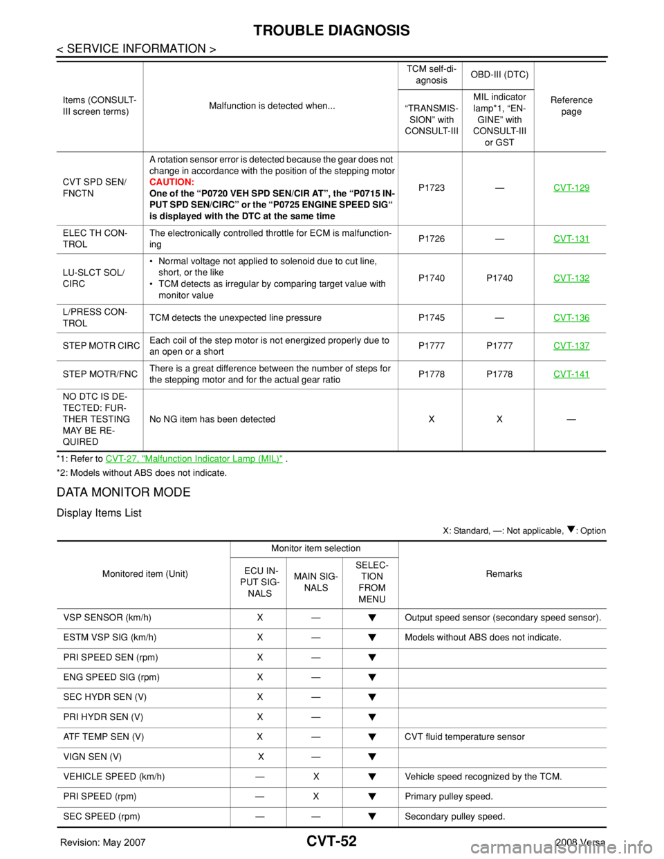
*1: Refer to CVT-27, "Malfunction Indicator Lamp (MIL)" .
*2: Models without ABS does not indicate.
DATA MONITOR MODE
Display Items List
X: Standard, —: Not applicable, : Option
CVT SPD SEN/
FNCTNA rotation sensor error is detected because the gear does not
change in accordance with the position of the stepping motor
CAUTION:
One of the “P0720 VEH SPD SEN/CIR AT”, the “P0715 IN-
PUT SPD SEN/CIRC” or the “P0725 ENGINE SPEED SIG“
is displayed with the DTC at the same timeP1723 —CVT-129
ELEC TH CON-
TROLThe electronically controlled throttle for ECM is malfunction-
ingP1726 —CVT-131
LU-SLCT SOL/
CIRC• Normal voltage not applied to solenoid due to cut line,
short, or the like
• TCM detects as irregular by comparing target value with
monitor valueP1740 P1740CVT-132
L/PRESS CON-
TROLTCM detects the unexpected line pressure P1745 —CVT-136
STEP MOTR CIRCEach coil of the step motor is not energized properly due to
an open or a shortP1777 P1777CVT-137
STEP MOTR/FNCThere is a great difference between the number of steps for
the stepping motor and for the actual gear ratioP1778 P1778CVT-141
NO DTC IS DE-
TECTED: FUR-
THER TESTING
MAY BE RE-
QUIREDNo NG item has been detected X X — Items (CONSULT-
III screen terms)Malfunction is detected when...TCM self-di-
agnosisOBD-III (DTC)
Reference
page “TRANSMIS-
SION” with
CONSULT-IIIMIL indicator
lamp*1, “EN-
GINE” with
CONSULT-III
or GST
Monitored item (Unit)Monitor item selection
Remarks ECU IN-
PUT SIG-
NALSMAIN SIG-
NALSSELEC-
TION
FROM
MENU
VSP SENSOR (km/h) X — Output speed sensor (secondary speed sensor).
ESTM VSP SIG (km/h) X — Models without ABS does not indicate.
PRI SPEED SEN (rpm) X —
ENG SPEED SIG (rpm) X —
SEC HYDR SEN (V) X —
PRI HYDR SEN (V) X —
ATF TEMP SEN (V) X — CVT fluid temperature sensor
VIGN SEN (V) X —
VEHICLE SPEED (km/h) — X Vehicle speed recognized by the TCM.
PRI SPEED (rpm) — X Primary pulley speed.
SEC SPEED (rpm) — — Secondary pulley speed.