2008 NISSAN LATIO remote start
[x] Cancel search: remote startPage 406 of 2771

TELEPHONE
AV-47
< SERVICE INFORMATION >
C
D
E
F
G
H
I
J
L
MA
B
AV
N
O
P
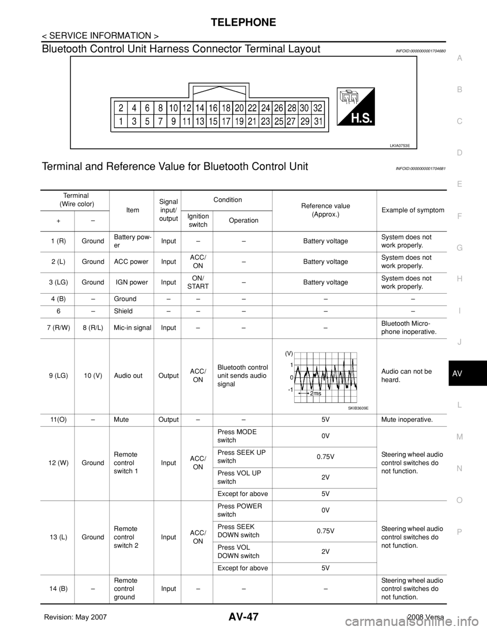
Bluetooth Control Unit Harness Connector Terminal LayoutINFOID:0000000001704680
Terminal and Reference Value for Bluetooth Control UnitINFOID:0000000001704681
LKIA0753E
Te r m i n a l
(Wire color)
ItemSignal
input/
outputCondition
Reference value
(Approx.)Example of symptom
+–Ignition
switchOperation
1 (R) GroundBattery pow-
erInput – – Battery voltageSystem does not
work properly.
2 (L) Ground ACC power InputACC/
ON– Battery voltageSystem does not
work properly.
3 (LG) Ground IGN power InputON/
START– Battery voltageSystem does not
work properly.
4 (B) – Ground – – – – –
6 – Shield – – – – –
7 (R/W) 8 (R/L) Mic-in signal Input – – –Bluetooth Micro-
phone inoperative.
9 (LG) 10 (V) Audio out OutputACC/
ONBluetooth control
unit sends audio
signalAudio can not be
heard.
11(O) – Mute Output – – 5V Mute inoperative.
12 (W) GroundRemote
control
switch 1InputACC/
ONPress MODE
switch 0V
Steering wheel audio
control switches do
not function. Press SEEK UP
switch0.75V
Press VOL UP
switch2V
Except for above 5V
13 (L) GroundRemote
control
switch 2InputACC/
ONPress POWER
switch 0V
Steering wheel audio
control switches do
not function. Press SEEK
DOWN switch0.75V
Press VOL
DOWN switch2V
Except for above 5V
14 (B) –Remote
control
groundInput – – –Steering wheel audio
control switches do
not function.
SKIB3609E
Page 510 of 2771

BL-76
< SERVICE INFORMATION >
INTELLIGENT KEY SYSTEM
System Description
INFOID:0000000001703999
• The Intelligent Key system is a system that makes it possible to lock and unlock the door locks (door lock/
unlock function), and start the engine (engine start function) by carrying around the Intelligent Key (without
some key operation), which operates based on the results of electronic ID verification using two-way com-
munications between the Intelligent Key and the vehicle (Intelligent Key unit).
• Vehicles equipped with a manual transmission include a key interlock solenoid located in the steering col-
umn to prevent accidental shut-off of the ignition switch and locking of the steering wheel during driving con-
dition when the vehicle is moving.
CAUTION:
The driver should always carry the Intelligent Key
• Operation of the remote controller buttons on the Intelligent Key also provides the same functions as the
remote control entry system. (Remote keyless entry functions)
• If an action that does not meet the operating conditions of the Intelligent Key system is taken, the buzzer
goes off to inform the driver. (Warning chime functions)
• When a door lock is locked or unlocked with request switch or remote controller button operation, the hazard
lamps flash and the buzzer (outside vehicle) sounds (Hazard and buzzer reminder function).
• Even if the Intelligent Key battery is completely discharged, the door locks can be locked and unlocked and
the engine started with the mechanical key built into the Intelligent Key.
• The settings for each function can be changed with the CONSULT-III.
• If an Intelligent Key is lost, a new Intelligent Key can be registered. A maximum of 4 Intelligent Keys can be
registered.
• It has been made possible to diagnose the system and register an Intelligent Key with the CONSULT-III.
DOOR LOCK/UNLOCK FUNCTION
Only when pressing the request switch, it is possible to lock and unlock the door by carrying around the Intelli-
gent Key (without some key operation).
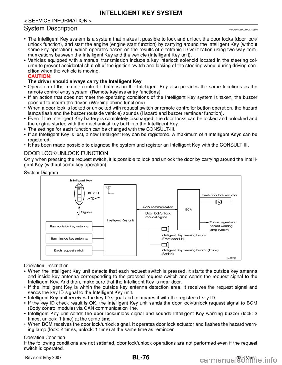
System Diagram
Operation Description
• When the Intelligent Key unit detects that each request switch is pressed, it starts the outside key antenna
and inside key antenna corresponding to the pressed request switch and sends the request signal to the
Intelligent Key. And then, make sure that the Intelligent Key is near door.
• If the Intelligent Key is within the outside key antenna detection area, it receives the request signal and
sends the key ID signal to the Intelligent Key unit.
• Intelligent Key unit receives the key ID signal and compares it with the registered key ID.
• If the key ID check result is OK, the Intelligent Key unit sends the door lock/unlock request signal to BCM
(Body control module) via CAN communication line.
• Intelligent Key unit sends the door lock/unlock signal and sounds Intelligent Key warning buzzer (lock: 2
times, unlock: 1 time) at the same time.
• When BCM receives the door lock/unlock signal, it operates door lock actuator and flashes the hazard warn-
ing lamp (lock: 2 times, unlock: 1 time) at the same time as reminder.
Operation Condition
If the following conditions are not satisfied, door lock/unlock operations are not performed even if the request
switch is operated.
LIIA2926E
Page 514 of 2771

BL-80
< SERVICE INFORMATION >
INTELLIGENT KEY SYSTEM
BCM sends headlamp request signal and horn signal to IPDM E/R. Then, IPDM E/R turns on and off head-
lamp and horn intermittently.
The headlamp flashes and the horn sounds intermittently.
The alarm automatically turns off:
• After 25 seconds
• When Intelligent Key unit receives any signal from remote controller of Intelligent Key
• When door request switch is pressed (Intelligent Key is outside vehicle)
Panic alarm function's press and holding time value can be changed in “PANIC ALARM DELAY” mode in
“WORK SUPPORT”. Refer to BL-101, "
CONSULT-III Application Item".
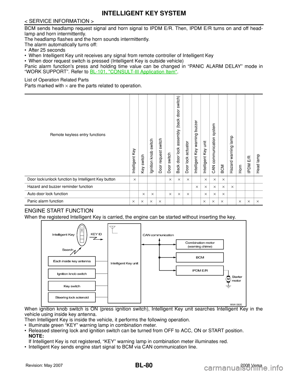
List of Operation Related Parts
Parts marked with × are the parts related to operation.
ENGINE START FUNCTION
When the registered Intelligent Key is carried, the engine can be started without inserting the key.
When ignition knob switch is ON (press ignition switch), Intelligent Key unit searches Intelligent Key in the
vehicle using inside key antenna.
Then Intelligent Key is inside the vehicle, it performs the following operation.
• Illuminate green “KEY” warning lamp in combination meter.
• Released steering lock and ignition switch can be turned from OFF to ACC, ON or START position.
NOTE:
If Intelligent Key is not registered, “KEY” warning lamp in combination meter illuminates red.
• Intelligent Key sends engine start signal to BCM via CAN communication line.
Remote keyless entry functions
Intelligent Key
Key switch
Ignition knob switch
Door request switch
Door switch
Back door lock assembly (back door switch)
Door lock actuator
Intelligent Key warning buzzer
Intelligent Key unit
CAN communication system
BCM
Hazard warning lamp
Horn
IPDM E/R
Head lamp
Door lock/unlock function by Intelligent Key button×××××××
Hazard and buzzer reminder function×××××
Auto door lock function×× ××× ×××
Panic alarm function×××× ××× ×××
WIIA1282E
Page 537 of 2771

INTELLIGENT KEY SYSTEM
BL-103
< SERVICE INFORMATION >
C
D
E
F
G
H
J
K
L
MA
B
BL
N
O
P
Trouble Diagnosis Symptom ChartINFOID:0000000001704012
KEY WARNING LAMP (GREEN) ILLUMINATES
NOTE:
• Before performing the diagnosis in the following table, check “Trouble Diagnosis Procedure”. Refer to BL-99,
"Trouble Diagnosis Procedure".
• Make sure that vehicle is under the condition shown in “Conditions of vehicle” before starting diagnosis, and
check each symptom.
• If the following “symptoms” are detected, check systems shown in the “Diagnoses/service procedure” col-
umn in this order.
Conditions of Vehicle (Operating Conditions)
• Intelligent Key is registered.
• Key is not inserted in ignition switch.
• One or more registered Intelligent Keys are in the vehicle.
KEY WARNING LAMP (RED) ILLUMINATES
NOTE:
• Before performing the diagnosis in the following table, check “Trouble Diagnosis Procedure”. Refer to BL-99,
"Trouble Diagnosis Procedure".
• Make sure that vehicle is under the condition shown in “Conditions of vehicle” before starting diagnosis, and
check each symptom.
• If the following “symptoms” are detected, check systems shown in the “Diagnoses/service procedure” col-
umn in this order.
Conditions of Vehicle (Operating Conditions)
• Intelligent Key is registered.
ANSWER BACK WITH I-KEY
LOCKBuzzer reminder function (lock operation) mode by door request switch (driver side, passenger
side and back door side) can be selected from the following with this mode. The operation mode
will be changed when “CHANGE SETT” on CONSULT-III screen is touched.
• BUZZER: Sound buzzer
• OFF: Non-operation
ANSWER BACK WITH I-KEY UN-
LOCKBuzzer reminder function (unlock operation) mode by door request switch can be changed to op-
erate (ON) or not operate (OFF) with this mode.
AUTO RELOCK TIMERAuto door lock timer mode can select the following with this mode.
• 1 minute
• OFF: Non-operation
PANIC ALARM DELAYPanic alarm button's pressing time on Intelligent Key remote control button can be selected from
the following with this mode. The operation mode will be changed when “CHANGE SETT” on
CONSULT-III screen is touched.
• 0.5 second
• 1.5 second
• OFF: Non-operation
P/W DOWN DELAYUnlock button's pressing time on Intelligent Key remote control button can be selected from the
following with this mode. The operation mode will be changed when “CHANGE SETT” on CON-
SULT-III screen is touched.
• 3 seconds
• 5 seconds
• OFF: Non-operation
ENGINE START BY I-KEYEngine start function mode can be changed to operate (ON) or not operate (OFF) with this mode.
The operation mode will be changed when “CHANGE SETT” on CONSULT-III screen is touched.
LOCK/UNLOCK BY I-KEYDoor lock/unlock function by door request switch (driver side, passenger side and back door side)
mode can be changed to operate (ON) or not operate (OFF) with this mode. The operation mode
will be changed when “CHANGE SETT” on CONSULT-III screen is touched. Monitor item Description
Symptom Diagnosis/service procedure Reference page
Ignition switch does not turn on with Intelligent Key.
[KEY warning lamp (green) illuminates].1. Check steering lock solenoid.BL-131
2. Replace Intelligent Key unit.BL-142
Page 540 of 2771

BL-106
< SERVICE INFORMATION >
INTELLIGENT KEY SYSTEM
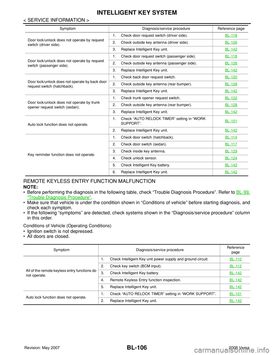
REMOTE KEYLESS ENTRY FUNCTION MALFUNCTION
NOTE:
• Before performing the diagnosis in the following table, check “Trouble Diagnosis Procedure”. Refer to BL-99,
"Trouble Diagnosis Procedure".
• Make sure that vehicle is under the condition shown in “Conditions of vehicle” before starting diagnosis, and
check each symptom.
• If the following “symptoms” are detected, check systems shown in the “Diagnosis/service procedure” column
in this order.
Conditions of Vehicle (Operating Conditions)
• Ignition switch is not depressed.
• All doors are closed.
Door lock/unlock does not operate by request
switch (driver side).1. Check door request switch (driver side).BL-1182. Check outside key antenna (driver side).BL-126
3. Replace Intelligent Key unit.BL-142
Door lock/unlock does not operate by request
switch (passenger side).1. Check door request switch (passenger side).BL-1182. Check outside key antenna (passenger side).BL-126
3. Replace Intelligent Key unit.BL-142
Door lock/unlock does not operate by back door
request switch (hatchback).1. Check back door request switch.BL-1202. Check outside key antenna (rear bumper).BL-128
3. Replace Intelligent Key unit.BL-142
Door lock/unlock does not operate by trunk
opener request switch (sedan).1. Check trunk opener request switch.BL-1222. Check outside key antenna (rear bumper).BL-128
3. Replace Intelligent Key unit.BL-142
Auto lock function does not operate.1. Check “AUTO RELOCK TIMER” setting in “WORK
SUPPORT”.BL-101
2. Replace Intelligent Key unit.BL-142
Key reminder function does not operate.1. Check door switch (hatchback).BL-114
2. Check door switch (sedan).BL-117
3. Check inside key antenna.BL-129
4. Check unlock sensor.BL-124
5. Check Intelligent Key battery.BL-142
6. Replace Intelligent Key unit.BL-142
Symptom Diagnosis/service procedure Reference page
Symptom Diagnosis/service procedureReference
page
All of the remote keyless entry functions do
not operate.1. Check Intelligent Key unit power supply and ground circuit.BL-110
2. Check key switch (BCM input).BL-112
3. Check Intelligent Key battery.BL-142
4. Remote Keyless Entry function inspection.BL-142
5. Replace Intelligent Key unit.BL-142
Auto lock function does not operate.1. Check “AUTO RELOCK TIMER” setting in “WORK SUPPORT”.BL-1012. Replace Intelligent Key unit.BL-142
Page 623 of 2771

VEHICLE SECURITY (THEFT WARNING) SYSTEM
BL-189
< SERVICE INFORMATION >
C
D
E
F
G
H
J
K
L
MA
B
BL
N
O
P
• to combination meter terminal 27 (security indicator lamp)
• through 40A fusible link (letter g, located in the fuse and fusible link box)
• to BCM terminal 70
• through 10A fuse [No. 8, located in the fuse block (J/B)]
• to BCM terminal 57
• through 10A fuse (No. 28, located in the fuse and fusible link box)
• to horn relay terminal 2
• through 15A fuse (No. 52, located in the IPDM E/R)
• to IPDM E/R internal CPU.
• through 20A fuse (No. 53, located in the IPDM E/R)
• to IPDM E/R internal CPU.
With the ignition switch in the ACC or ON position, power is supplied• through 10A fuse [No. 20, located in the fuse block (J/B)]
• to BCM terminal 11.
With the ignition switch in the ON or START position, power is supplied• through 10A fuse [No. 6, located in the fuse block (J/B)]
• to BCM terminal 38.
Ground is supplied• to BCM terminal 67
• through body grounds M57 and M61.
INITIAL CONDITION TO ACTIVATE THE SYSTEM
The operation of the vehicle security system is controlled by the doors and trunk (sedan).
To activate the vehicle security system, BCM must receive signals indicating the ignition switch is OFF, doors
and trunk (sedan) are closed and locked.
When a door or trunk (sedan) is open, BCM terminal 12, 13, 42, 43, 47 or 48 receives a ground signal from
each door or trunk switch. In addition to BCM, when back door is open, the Intelligent Key unit terminal 23
receives a ground signal from back door or trunk (sedan) through BCM terminal 30.
When front door LH is unlocked, BCM terminal 46 receives a signal from terminal 6 of main power window and
door lock/unlock switch.
When front door RH is unlocked, BCM terminal 46 receives a signal from terminal 2 of power window and door
lock/unlock switch RH.
VEHICLE SECURITY SYSTEM ALARM OPERATION
The vehicle security system is triggered by
• Opening a door without using the key, keyfob or Intelligent Key.
• Opening trunk without using the key, keyfob or Intelligent Key (sedan).
The vehicle security system will be triggered once the system is in armed phase,
• when BCM receives a ground signal at terminals 12, 13, 47, 48 (front or rear door switch), terminal 42
(sedan, trunk switch) or terminal 43 (hatchback, back door switch).
When the vehicle security system is triggered, ground is supplied intermittently
• from IPDM E/R terminal 45
• to horn relay terminal 1.
The headlamps flash and the horn sounds intermittently.
The alarm automatically turns off after 50 seconds, but will reactivate if the vehicle is tampered with again.
VEHICLE SECURITY SYSTEM DEACTIVATION
To deactivate the vehicle security system, a door or trunk (sedan) must be unlocked with the key, keyfob or
Intelligent Key.
When the key is used to unlock the driver door, BCM terminal 7 receives signal
• from terminal 3 of the front door key cylinder switch LH.
When the key is used to open the trunk (sedan), BCM terminal 41 receives signal
• from terminal 1 of the trunk key cylinder switch.
When the BCM receives an unlock signal from keyfob, Intelligent Key, front door key cylinder switch LH or
trunk key cylinder switch (sedan), the vehicle security system is deactivated (Disarmed phase).
PANIC ALARM OPERATION
Intelligent Key and remote keyless entry system may or may not operate vehicle security system (horn and
headlamps) as required.
When the remote keyless entry system is triggered, ground is supplied intermittently
Page 2242 of 2771

ILLUMINATION
LT-105
< SERVICE INFORMATION >
C
D
E
F
G
H
I
J
L
MA
B
LT
N
O
P
ILLUMINATION
System DescriptionINFOID:0000000001704480
The control of the illumination lamps operation is dependent upon the position of the lighting switch. When the
lighting switch is placed in the 1ST or 2ND position, the BCM (body control module) receives input signal
requesting the illumination lamps to illuminate. This input signal is communicated to IPDM E/R (intelligent
power distribution module engine room) across CAN communication lines. CPU (central processing unit)
located in the IPDM E/R controls the tail lamp relay coil. This relay, when energized, directs power to the illu-
mination lamps, which then illuminate.
Power is supplied at all times
• to ignition relay, located in IPDM E/R,
• to tail lamp relay, located in IPDM E/R,
• through 15A fuse (No. 52, located in IPDM E/R) and
• through 20A fuse (No. 53, located in IPDM E/R)
• to CPU located in IPDM E/R,
• through 40A fusible link (letter g , located in fuse and fusible link box)
• to BCM terminal 70, and
• through 10A fuse [No. 8, located in fuse block (J/B)]
• to BCM terminal 57.
With the ignition switch in the ON or START position, power is supplied
• to ignition relay, located in IPDM E/R, and
• through 10A fuse [No. 6, located in fuse block (J/B)]
• to BCM terminal 38.
With the ignition switch in the ACC or ON position, power is supplied
• through 10A fuse [No. 20, located in fuse block (J/B)]
• to BCM terminal 11.
Ground is supplied
• to BCM terminal 67
• through grounds M57 and M61, and
• to IPDM E/R terminals 39 and 59
• through grounds E15 and E24.
ILLUMINATION OPERATION BY LIGHTING SWITCH
With the lighting switch in the 1ST or 2ND position, BCM receives input signal requesting the illumination
lamps to illuminate. This input signal is communicated to IPDM E/R across CAN communication lines. CPU
located in the IPDM E/R controls the tail lamp relay coil, which, when energized, directs power
• through 10A fuse (No. 37, located in IPDM E/R)
• through IPDM E/R terminal 29
• to microphone terminal 3 (with Bluetooth)
• to illumination control switch terminal 1
• to glove box lamp terminal 1 (with glovebox lamp)
• to audio unit terminal 9
• to front air control terminal 5
• to A/T device terminal 3 (with 4-speed A/T)
• to CVT device terminal 3 (with CVT)
• to hazard switch terminal 3
• to combination meter terminal 12
• to door mirror remote control switch terminal 16, and
Ground is supplied
• to microphone terminal 2 (with Bluetooth)
• to glove box lamp terminal 2 (with glove box lamp), and
• to illumination control switch terminal 3
• through grounds M57 and M61.
The illumination control switch controls illumination intensity by varying the ground to the following
• through illumination control switch terminal 2
• to audio unit terminal 8
• to front air control terminal 6
• to A/T device terminal 4 (with 4-speed A/T)
• to CVT device terminal 3 (with CVT)
• to hazard switch terminal 4