2008 NISSAN LATIO ABS
[x] Cancel search: ABSPage 1125 of 2771
ON BOARD DIAGNOSTIC (OBD) SYSTEM
EC-51
< SERVICE INFORMATION >
C
D
E
F
G
H
I
J
K
L
MA
EC
N
P O
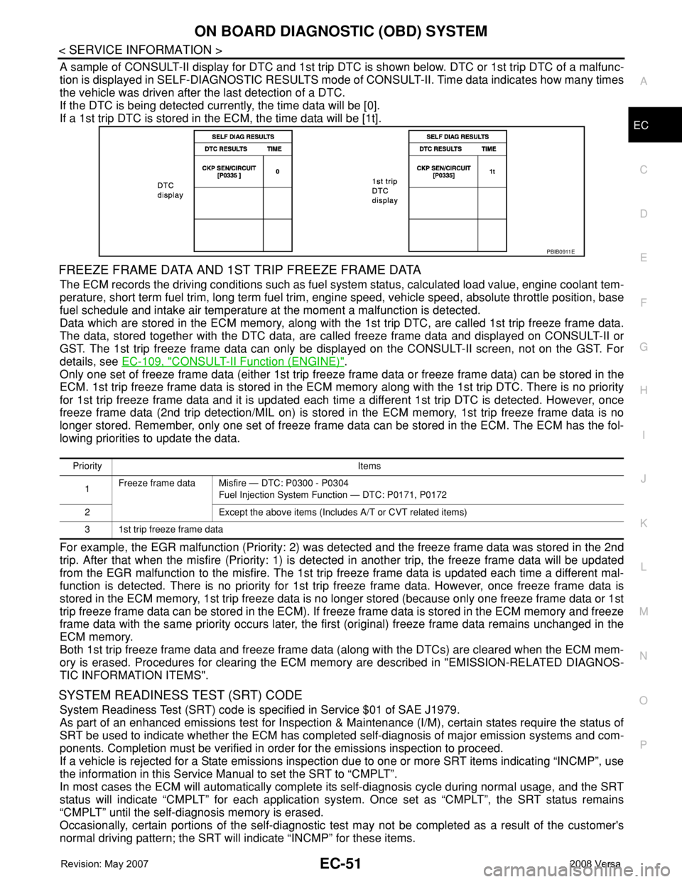
A sample of CONSULT-II display for DTC and 1st trip DTC is shown below. DTC or 1st trip DTC of a malfunc-
tion is displayed in SELF-DIAGNOSTIC RESULTS mode of CONSULT-II. Time data indicates how many times
the vehicle was driven after the last detection of a DTC.
If the DTC is being detected currently, the time data will be [0].
If a 1st trip DTC is stored in the ECM, the time data will be [1t].
FREEZE FRAME DATA AND 1ST TRIP FREEZE FRAME DATA
The ECM records the driving conditions such as fuel system status, calculated load value, engine coolant tem-
perature, short term fuel trim, long term fuel trim, engine speed, vehicle speed, absolute throttle position, base
fuel schedule and intake air temperature at the moment a malfunction is detected.
Data which are stored in the ECM memory, along with the 1st trip DTC, are called 1st trip freeze frame data.
The data, stored together with the DTC data, are called freeze frame data and displayed on CONSULT-II or
GST. The 1st trip freeze frame data can only be displayed on the CONSULT-II screen, not on the GST. For
details, see EC-109, "
CONSULT-II Function (ENGINE)".
Only one set of freeze frame data (either 1st trip freeze frame data or freeze frame data) can be stored in the
ECM. 1st trip freeze frame data is stored in the ECM memory along with the 1st trip DTC. There is no priority
for 1st trip freeze frame data and it is updated each time a different 1st trip DTC is detected. However, once
freeze frame data (2nd trip detection/MIL on) is stored in the ECM memory, 1st trip freeze frame data is no
longer stored. Remember, only one set of freeze frame data can be stored in the ECM. The ECM has the fol-
lowing priorities to update the data.
For example, the EGR malfunction (Priority: 2) was detected and the freeze frame data was stored in the 2nd
trip. After that when the misfire (Priority: 1) is detected in another trip, the freeze frame data will be updated
from the EGR malfunction to the misfire. The 1st trip freeze frame data is updated each time a different mal-
function is detected. There is no priority for 1st trip freeze frame data. However, once freeze frame data is
stored in the ECM memory, 1st trip freeze data is no longer stored (because only one freeze frame data or 1st
trip freeze frame data can be stored in the ECM). If freeze frame data is stored in the ECM memory and freeze
frame data with the same priority occurs later, the first (original) freeze frame data remains unchanged in the
ECM memory.
Both 1st trip freeze frame data and freeze frame data (along with the DTCs) are cleared when the ECM mem-
ory is erased. Procedures for clearing the ECM memory are described in "EMISSION-RELATED DIAGNOS-
TIC INFORMATION ITEMS".
SYSTEM READINESS TEST (SRT) CODE
System Readiness Test (SRT) code is specified in Service $01 of SAE J1979.
As part of an enhanced emissions test for Inspection & Maintenance (I/M), certain states require the status of
SRT be used to indicate whether the ECM has completed self-diagnosis of major emission systems and com-
ponents. Completion must be verified in order for the emissions inspection to proceed.
If a vehicle is rejected for a State emissions inspection due to one or more SRT items indicating “INCMP”, use
the information in this Service Manual to set the SRT to “CMPLT”.
In most cases the ECM will automatically complete its self-diagnosis cycle during normal usage, and the SRT
status will indicate “CMPLT” for each application system. Once set as “CMPLT”, the SRT status remains
“CMPLT” until the self-diagnosis memory is erased.
Occasionally, certain portions of the self-diagnostic test may not be completed as a result of the customer's
normal driving pattern; the SRT will indicate “INCMP” for these items.
PBIB0911E
Priority Items
1Freeze frame data Misfire — DTC: P0300 - P0304
Fuel Injection System Function — DTC: P0171, P0172
2 Except the above items (Includes A/T or CVT related items)
3 1st trip freeze frame data
Page 1164 of 2771
EC-90
< SERVICE INFORMATION >
TROUBLE DIAGNOSIS
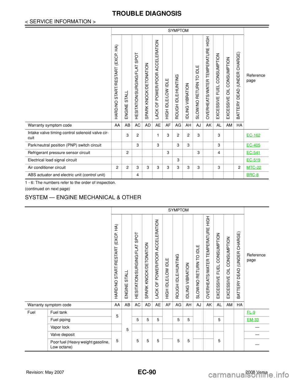
1 - 6: The numbers refer to the order of inspection.
(continued on next page)
SYSTEM — ENGINE MECHANICAL & OTHER
Intake valve timing control solenoid valve cir-
cuit32 13223 3EC-162
Park/neutral position (PNP) switch circuit 3 3 3 3 3EC-405
Refrigerant pressure sensor circuit 2 3 3 4EC-541
Electrical load signal circuit 3EC-519
Air conditioner circuit 223333333 3 2MTC-22
ABS actuator and electric unit (control unit) 4BRC-8
SYMPTOM
Reference
page
HARD/NO START/RESTART (EXCP. HA)
ENGINE STALL
HESITATION/SURGING/FLAT SPOT
SPARK KNOCK/DETONATION
LACK OF POWER/POOR ACCELERATION
HIGH IDLE/LOW IDLE
ROUGH IDLE/HUNTING
IDLING VIBRATION
SLOW/NO RETURN TO IDLE
OVERHEATS/WATER TEMPERATURE HIGH
EXCESSIVE FUEL CONSUMPTION
EXCESSIVE OIL CONSUMPTION
BATTERY DEAD (UNDER CHARGE)
Warranty symptom code AA AB AC AD AE AF AG AH AJ AK AL AM HA
Fuel Fuel tank
5
5FL-9
Fuel piping 5 5 5 5 5 5EM-33
Va p o r l o c k—
Valve deposit
5 555 55 5—
Poor fuel (Heavy weight gasoline,
Low octane)—
Page 1186 of 2771

EC-112
< SERVICE INFORMATION >
TROUBLE DIAGNOSIS
*: This function is not necessary in the usual service procedure.
SELF-DIAG RESULTS MODE
Self Diagnostic Item
Regarding items of DTC and 1st trip DTC, refer to EC-47, "Emission-related Diagnostic Information".
Freeze Frame Data and 1st Trip Freeze Frame Data
EVAP SYSTEM CLOSE CLOSE THE EVAP CANISTER VENT CONTROL VALVE IN
ORDER TO MAKE EVAP SYSTEM CLOSE UNDER THE
FOLLOWING CONDITIONS.
•IGN SW “ON”
• ENGINE NOT RUNNING
• AMBIENT TEMPERATURE IS ABOVE 0°C (32°F).
• NO VACUUM AND NO HIGH PRESSURE IN EVAP SYS-
TEM
• FUEL TANK TEMP. IS MORE THAN 0°C (32°F).
• WITHIN 10 MINUTES AFTER STARTING “EVAP SYS-
TEM CLOSE”
• WHEN TRYING TO EXECUTE “EVAP SYSTEM CLOSE”
UNDER THE CONDITION EXCEPT ABOVE, CONSULT-
II WILL DISCONTINUE IT AND DISPLAY APPROPRIATE
INSTRUCTION.
NOTE:
WHEN STARTING ENGINE, CONSULT-II MAY DISPLAY
“BATTERY VOLTAGE IS LOW. CHARGE BATTERY”,
EVEN IN USING CHARGED BATTERY.When detecting EVAP vapor leak
point of EVAP system
TARGET IDLE RPM ADJ* • IDLE CONDITION When setting target idle speed
TARGET IGN TIM ADJ* • IDLE CONDITION When adjusting target ignition tim-
ing
VIN REGISTRATION • IN THIS MODE, VIN IS REGISTERED IN ECM. When registering VIN in ECMWORK ITEM CONDITION USAGE
Freeze frame data
item*Description
DIAG TROUBLE
CODE
[PXXXX]• The engine control component part/control system has a trouble code, it is displayed as PXXXX.
(Refer to EC-9
)
FUEL SYS-B1• “Fuel injection system status” at the moment a malfunction is detected is displayed.
• One mode in the following is displayed.
Mode2: Open loop due to detected system malfunction
Mode3: Open loop due to driving conditions (power enrichment, deceleration enleanment)
Mode4: Closed loop - using oxygen sensor(s) as feedback for fuel control
Mode5: Open loop - has not yet satisfied condition to go to closed loop
CAL/LD VALUE [%] • The calculated load value at the moment a malfunction is detected is displayed.
COOLANT TEMP
[°C] or [°F]• The engine coolant temperature at the moment a malfunction is detected is displayed.
L-FUEL TRM-B1 [%]• “Long-term fuel trim” at the moment a malfunction is detected is displayed.
• The long-term fuel trim indicates much more gradual feedback compensation to the base fuel schedule than
short-term fuel trim.
S-FUEL TRM-B1 [%]• “Short-term fuel trim” at the moment a malfunction is detected is displayed.
• The short-term fuel trim indicates dynamic or instantaneous feedback compensation to the base fuel sched-
ule.
ENGINE SPEED [rpm] • The engine speed at the moment a malfunction is detected is displayed.
VEHICL SPEED
[km/h] or [mph]• The vehicle speed at the moment a malfunction is detected is displayed.
ABSOL TH-P/S [%] • The throttle valve opening angle at the moment a malfunction is detected is displayed.
B/FUEL SCHDL
[msec]• The base fuel schedule at the moment a malfunction is detected is displayed.
Page 1465 of 2771
DTC P0500 VSS
EC-391
< SERVICE INFORMATION >
C
D
E
F
G
H
I
J
K
L
MA
EC
N
P O
DTC P0500 VSS
DescriptionINFOID:0000000001702900
NOTE:
•If DTC P0500 is displayed with DTC U1000 or U1001, first perform the trouble diagnosis for DTC
U1000, U1001. Refer to EC-143
.
•If DTC P0500 is displayed with DTC U1010, first perform the trouble diagnosis for DTC U1010. Refer
to EC-145
.
The vehicle speed signal is sent to the combination meter from “ABS actuator and electric unit (control unit)”
through CAN communication line. The combination meter then sends a signal to the ECM through CAN com-
munication line.
On Board Diagnosis LogicINFOID:0000000001702901
FAIL-SAFE MODE
When the malfunction is detected, ECM enters fail-safe mode.
DTC Confirmation ProcedureINFOID:0000000001702902
CAUTION:
Always drive vehicle at a safe speed.
NOTE:
If DTC Confirmation Procedure has been previously conducted, always turn ignition switch OFF and wait at
least 10 seconds before conducting the next test.
TESTING CONDITION:
Steps 1 and 2 may be conducted with the drive wheels lifted in the shop or by driving the vehicle. If a
road test is expected to be easier, it is unnecessary to lift the vehicle.
WITH CONSULT-II
1. Start engine.
2. Read “VHCL SPEED SE” in “DATA MONITOR” mode with CONSULT-II. The vehicle speed on CONSULT-
II should exceed 10 km/h (6 MPH) when rotating wheels with suitable gear position.
If NG, go to EC-392, "
Diagnosis Procedure".
If OK, go to following step.
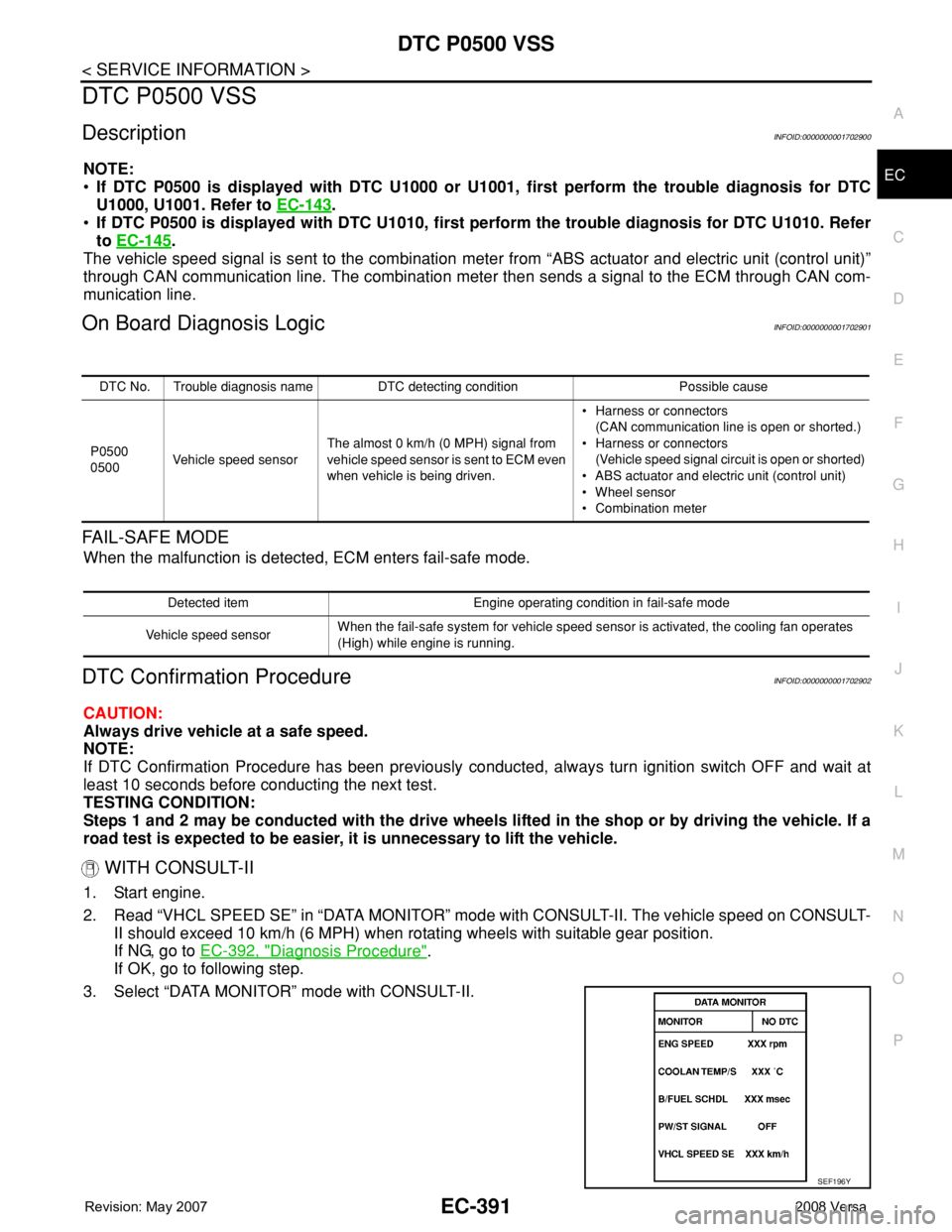
3. Select “DATA MONITOR” mode with CONSULT-II.
DTC No. Trouble diagnosis name DTC detecting condition Possible cause
P0500
0500Vehicle speed sensorThe almost 0 km/h (0 MPH) signal from
vehicle speed sensor is sent to ECM even
when vehicle is being driven.• Harness or connectors
(CAN communication line is open or shorted.)
• Harness or connectors
(Vehicle speed signal circuit is open or shorted)
• ABS actuator and electric unit (control unit)
• Wheel sensor
• Combination meter
Detected item Engine operating condition in fail-safe mode
Vehicle speed sensorWhen the fail-safe system for vehicle speed sensor is activated, the cooling fan operates
(High) while engine is running.
SEF196Y
Page 1466 of 2771
EC-392
< SERVICE INFORMATION >
DTC P0500 VSS
4. Warm engine up to normal operating temperature.
5. Maintain the following conditions for at least 60 consecutive seconds.
6. If 1st trip DTC is detected, go to EC-392, "
Diagnosis Procedure".
Overall Function CheckINFOID:0000000001702903
Use this procedure to check the overall function of the vehicle speed signal circuit. During this check, a 1st trip
DTC might not be confirmed.
WITH GST
1. Lift up drive wheels.
2. Start engine.
3. Read vehicle speed signal in Service $01 with GST.
The vehicle speed signal on GST should be able to exceed 10 km/h (6 MPH) when rotating wheels with
suitable gear position.
4. If NG, go to EC-392, "
Diagnosis Procedure".
Diagnosis ProcedureINFOID:0000000001702904
1.CHECK DTC WITH “ABS ACTUATOR AND ELECTRIC UNIT (CONTROL UNIT)”
Refer to BRC-8
.
OK or NG
OK >> GO TO 2.
NG >> Repair or replace.
2.CHECK COMBINATION METER
Refer to DI-4
.
>>INSPECTION END
ENG SPEED More than 1,600 rpm
COOLAN TEMP/S More than 70°C (158°F)
B/FUEL SCHDL 6.0 - 31.8 msec
Shift lever Suitable position
PW/ST SIGNAL OFF
Page 1522 of 2771
EC-448
< SERVICE INFORMATION >
DTC P1574 ASCD VEHICLE SPEED SENSOR
Diagnosis Procedure
INFOID:0000000001702968
1.CHECK DTC WITH TCM
Check DTC with TCM. Refer to AT- 3 6
(A/T) or CVT-26 (CVT).
OK or NG
OK >> GO TO 2.
NG >> Perform trouble shooting relevant to DTC indicated.
2.CHECK DTC WITH “ABS ACTUATOR AND ELECTRIC UNIT”
Refer to BRC-8
.
OK or NG
OK >> GO TO 3.
NG >> Repair or replace.
3.CHECK COMBINATION METER
Check combination meter function.
Refer to DI-4
.
>>INSPECTION END
Page 1637 of 2771
EI-14
< ON-VEHICLE REPAIR >
FRONT BUMPER
ON-VEHICLE REPAIR
FRONT BUMPER
Removal and InstallationINFOID:0000000001704218
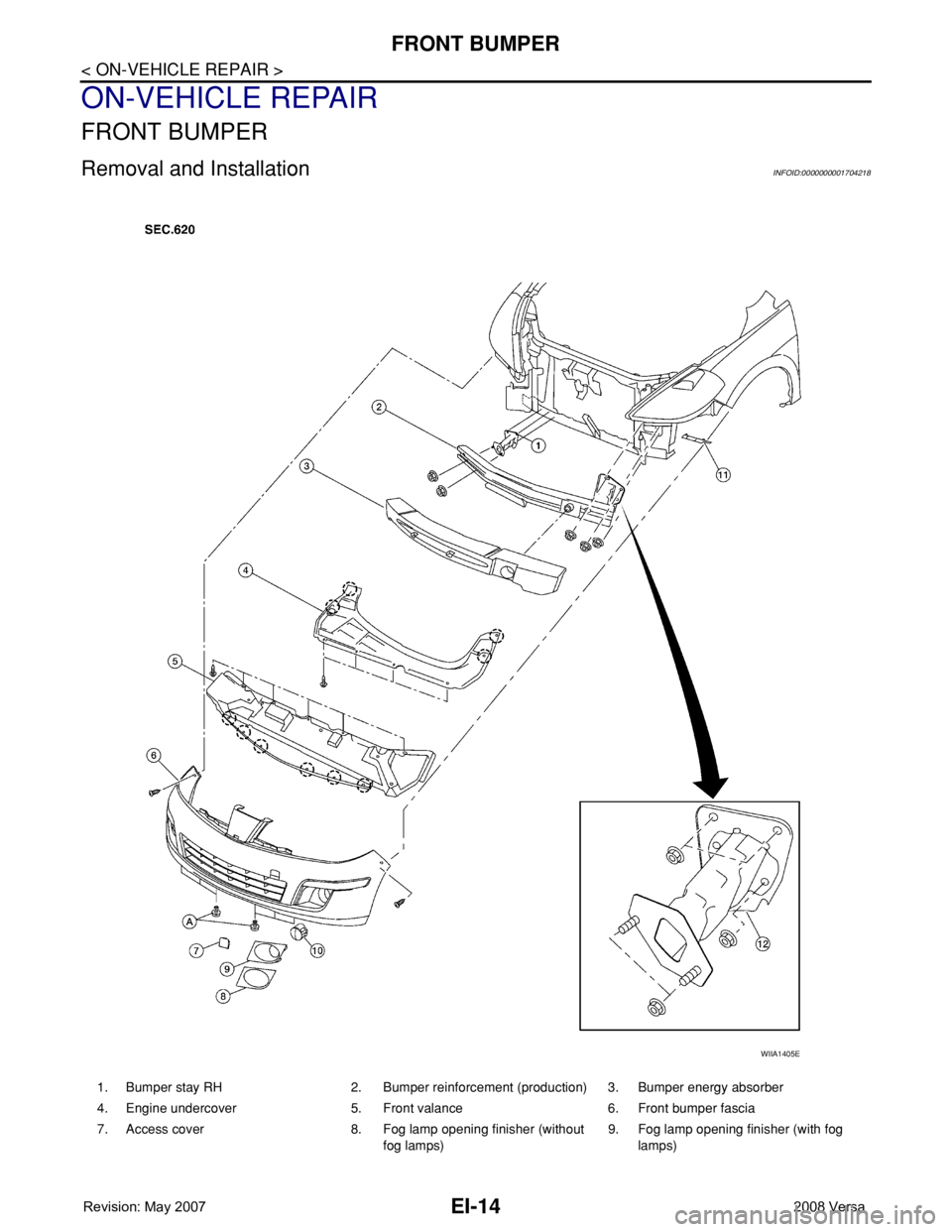
1. Bumper stay RH 2. Bumper reinforcement (production) 3. Bumper energy absorber
4. Engine undercover 5. Front valance 6. Front bumper fascia
7. Access cover 8. Fog lamp opening finisher (without
fog lamps)9. Fog lamp opening finisher (with fog
lamps)
WIIA1405E
Page 1638 of 2771
FRONT BUMPER
EI-15
< ON-VEHICLE REPAIR >
C
D
E
F
G
H
J
K
L
MA
B
EI
N
O
P
CAUTION:
Bumper fascia is made of resin. Do not apply strong force to it, and be careful to prevent contact with
oil.
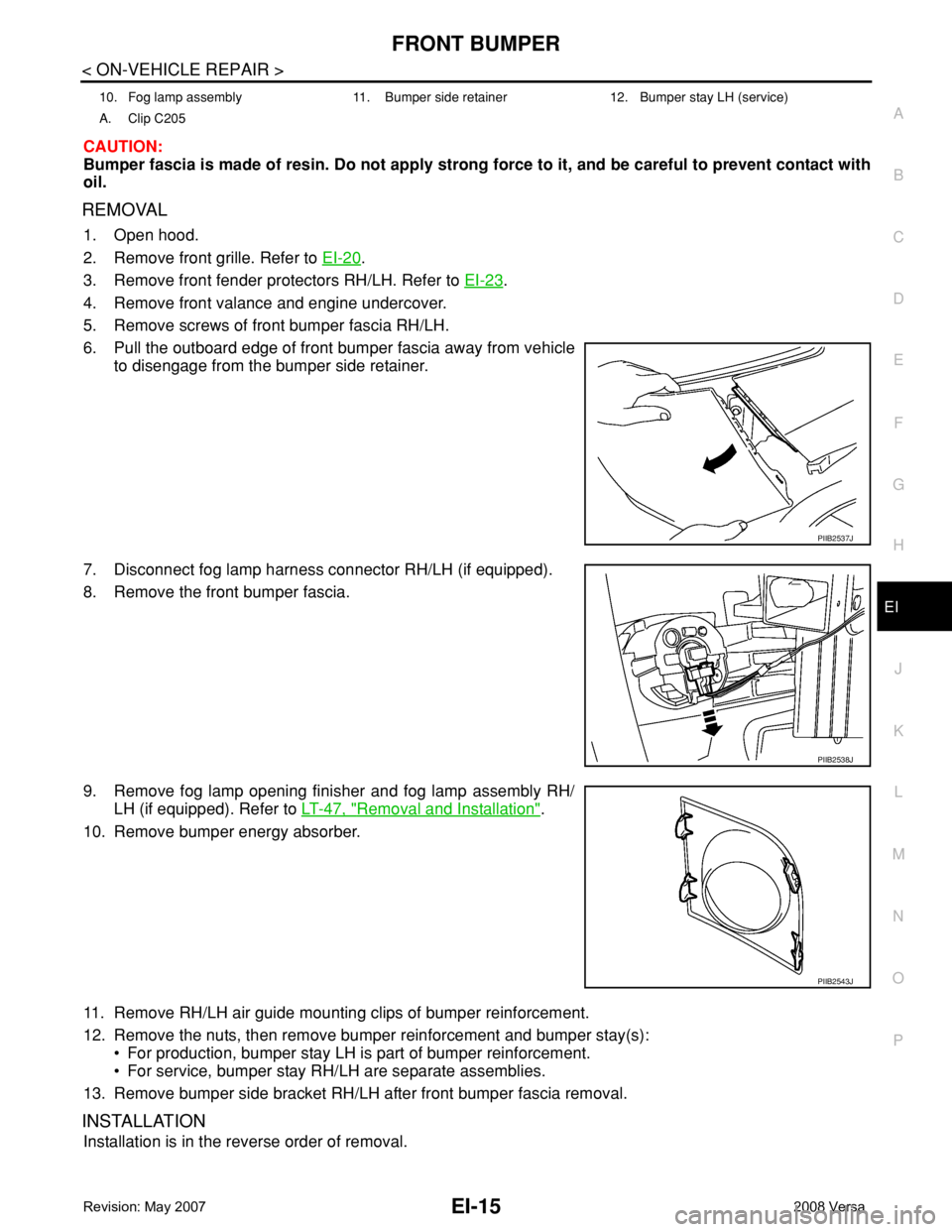
REMOVAL
1. Open hood.
2. Remove front grille. Refer to EI-20
.
3. Remove front fender protectors RH/LH. Refer to EI-23
.
4. Remove front valance and engine undercover.
5. Remove screws of front bumper fascia RH/LH.
6. Pull the outboard edge of front bumper fascia away from vehicle
to disengage from the bumper side retainer.
7. Disconnect fog lamp harness connector RH/LH (if equipped).
8. Remove the front bumper fascia.
9. Remove fog lamp opening finisher and fog lamp assembly RH/
LH (if equipped). Refer to LT-47, "
Removal and Installation".
10. Remove bumper energy absorber.
11. Remove RH/LH air guide mounting clips of bumper reinforcement.
12. Remove the nuts, then remove bumper reinforcement and bumper stay(s):
• For production, bumper stay LH is part of bumper reinforcement.
• For service, bumper stay RH/LH are separate assemblies.
13. Remove bumper side bracket RH/LH after front bumper fascia removal.
INSTALLATION
Installation is in the reverse order of removal.
10. Fog lamp assembly 11. Bumper side retainer 12. Bumper stay LH (service)
A. Clip C205
PIIB2537J
PIIB2538J
PIIB2543J