2008 NISSAN LATIO ABS
[x] Cancel search: ABSPage 1991 of 2771

INSTRUMENT PANEL ASSEMBLY
IP-25
< ON-VEHICLE REPAIR >
C
D
E
F
G
H
J
K
L
MA
B
IP
N
O
P Disassembly
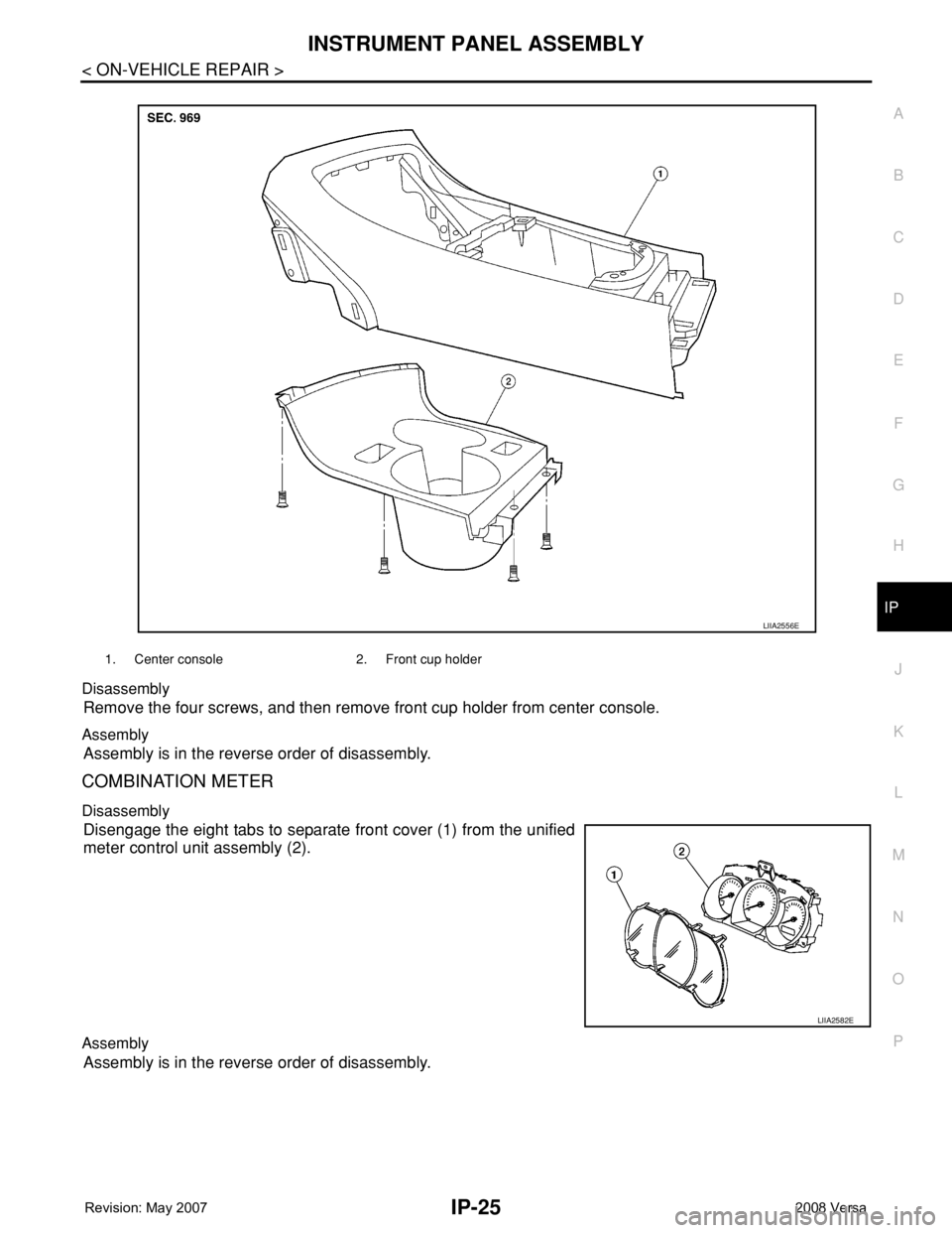
Remove the four screws, and then remove front cup holder from center console.
Assembly
Assembly is in the reverse order of disassembly.
COMBINATION METER
Disassembly
Disengage the eight tabs to separate front cover (1) from the unified
meter control unit assembly (2).
Assembly
Assembly is in the reverse order of disassembly.
1. Center console 2. Front cup holder
LIIA2556E
LIIA2582E
Page 1992 of 2771

LAN-1
ELECTRICAL
C
D
E
F
G
H
I
J
L
M
SECTION LAN
A
B
LAN
N
O
P
CONTENTS
LAN SYSTEM
CAN FUNDAMENTAL
PRECAUTION ...............................................
5
PRECAUTIONS ...................................................5
Precautions for Trouble Diagnosis ............................5
Precautions for Harness Repair ................................5
FUNCTION DIAGNOSIS ...............................6
CAN COMMUNICATION SYSTEM .....................6
System Description ...................................................6
System Diagram ........................................................6
CAN Communication Control Circuit .........................7
DIAG ON CAN .....................................................8
Description ................................................................8
System Diagram ........................................................8
TROUBLE DIAGNOSIS ......................................9
Condition of Error Detection ......................................9
Symptom When Error Occurs in CAN Communi-
cation System ............................................................
9
CAN Diagnosis with CONSULT-III ..........................12
Self-Diagnosis .........................................................12
CAN Diagnostic Support Monitor ............................12
How to Use CAN Communication Signal Chart ......14
BASIC INSPECTION ...................................15
DIAGNOSIS AND REPAIR WORKFLOW .........15
Trouble Diagnosis Flow Chart .................................15
Trouble Diagnosis Procedure ..................................15
CAN
HOW TO USE THIS MANUAL .....................
20
HOW TO USE THIS SECTION ...........................20
Caution ....................................................................20
Abbreviation List ......................................................20
PRECAUTION ..............................................21
PRECAUTIONS .................................................21
Precaution for Supplemental Restraint System
(SRS) "AIR BAG" and "SEAT BELT PRE-TEN-
SIONER" .................................................................
21
Precautions for Trouble Diagnosis ..........................21
Precautions for Harness Repair ..............................21
BASIC INSPECTION ...................................22
DIAGNOSIS AND REPAIR WORKFLOW ........22
Interview Sheet ........................................................22
FUNCTION DIAGNOSIS ..............................23
CAN COMMUNICATION SYSTEM ...................23
CAN System Specification Chart .............................23
CAN Communication Signal Chart ..........................23
COMPONENT DIAGNOSIS .........................26
CAN COMMUNICATION SYSTEM ...................26
Component Parts Location ......................................26
Schematic ................................................................27
Wiring Diagram - CAN - ...........................................28
MALFUNCTION AREA CHART ........................30
Main Line .................................................................30
Branch Line .............................................................30
Short Circuit .............................................................30
MAIN LINE BETWEEN DLC AND ABS CIR-
CUIT ..................................................................
31
Diagnosis Procedure ...............................................31
MAIN LINE BETWEEN DLC AND TCM CIR-
CUIT ..................................................................
32
Diagnosis Procedure ...............................................32
ECM BRANCH LINE CIRCUIT .........................33
Diagnosis Procedure ...............................................33
BCM BRANCH LINE CIRCUIT .........................34
Diagnosis Procedure ...............................................34
Page 1993 of 2771

LAN-2
DLC BRANCH LINE CIRCUIT ...........................35
Diagnosis Procedure ..............................................35
EPS BRANCH LINE CIRCUIT ...........................36
Diagnosis Procedure ..............................................36
I-KEY BRANCH LINE CIRCUIT ........................37
Diagnosis Procedure ..............................................37
M&A BRANCH LINE CIRCUIT ..........................38
Diagnosis Procedure ..............................................38
ABS BRANCH LINE CIRCUIT ..........................39
Diagnosis Procedure ..............................................39
TCM BRANCH LINE CIRCUIT ..........................40
Diagnosis Procedure ..............................................40
IPDM-E BRANCH LINE CIRCUIT .....................41
Diagnosis Procedure ..............................................41
CAN COMMUNICATION CIRCUIT ....................42
Diagnosis Procedure ..............................................42
CAN SYSTEM (TYPE 1)
COMPONENT DIAGNOSIS ........................
44
ECM BRANCH LINE CIRCUIT ..........................44
Diagnosis Procedure ..............................................44
BCM BRANCH LINE CIRCUIT ..........................45
Diagnosis Procedure ..............................................45
DLC BRANCH LINE CIRCUIT ...........................46
Diagnosis Procedure ..............................................46
EPS BRANCH LINE CIRCUIT ...........................47
Diagnosis Procedure ..............................................47
M&A BRANCH LINE CIRCUIT ..........................48
Diagnosis Procedure ..............................................48
IPDM-E BRANCH LINE CIRCUIT .....................49
Diagnosis Procedure ..............................................49
CAN COMMUNICATION CIRCUIT ....................50
Diagnosis Procedure ..............................................50
CAN SYSTEM (TYPE 2)
COMPONENT DIAGNOSIS ........................
52
ECM BRANCH LINE CIRCUIT ..........................52
Diagnosis Procedure ..............................................52
BCM BRANCH LINE CIRCUIT ..........................53
Diagnosis Procedure ..............................................53
DLC BRANCH LINE CIRCUIT ...........................54
Diagnosis Procedure ..............................................54
EPS BRANCH LINE CIRCUIT ...........................55
Diagnosis Procedure ..............................................55
I-KEY BRANCH LINE CIRCUIT ........................56
Diagnosis Procedure ...............................................56
M&A BRANCH LINE CIRCUIT ..........................57
Diagnosis Procedure ...............................................57
IPDM-E BRANCH LINE CIRCUIT .....................58
Diagnosis Procedure ...............................................58
CAN COMMUNICATION CIRCUIT ...................59
Diagnosis Procedure ...............................................59
CAN SYSTEM (TYPE 3)
COMPONENT DIAGNOSIS .......................
61
MAIN LINE BETWEEN DLC AND ABS CIR-
CUIT ...................................................................
61
Diagnosis Procedure ...............................................61
ECM BRANCH LINE CIRCUIT ..........................62
Diagnosis Procedure ...............................................62
BCM BRANCH LINE CIRCUIT ..........................63
Diagnosis Procedure ...............................................63
DLC BRANCH LINE CIRCUIT ..........................64
Diagnosis Procedure ...............................................64
EPS BRANCH LINE CIRCUIT ...........................65
Diagnosis Procedure ...............................................65
M&A BRANCH LINE CIRCUIT ..........................66
Diagnosis Procedure ...............................................66
ABS BRANCH LINE CIRCUIT ..........................67
Diagnosis Procedure ...............................................67
IPDM-E BRANCH LINE CIRCUIT .....................68
Diagnosis Procedure ...............................................68
CAN COMMUNICATION CIRCUIT ...................69
Diagnosis Procedure ...............................................69
CAN SYSTEM (TYPE 4)
COMPONENT DIAGNOSIS .......................
71
MAIN LINE BETWEEN DLC AND ABS CIR-
CUIT ...................................................................
71
Diagnosis Procedure ...............................................71
ECM BRANCH LINE CIRCUIT ..........................72
Diagnosis Procedure ...............................................72
BCM BRANCH LINE CIRCUIT ..........................73
Diagnosis Procedure ...............................................73
DLC BRANCH LINE CIRCUIT ..........................74
Diagnosis Procedure ...............................................74
EPS BRANCH LINE CIRCUIT ...........................75
Diagnosis Procedure ...............................................75
I-KEY BRANCH LINE CIRCUIT .....................
Page 1994 of 2771

LAN-3
C
D
E
F
G
H
I
J
L
MA
B
LAN
N
O
P Diagnosis Procedure ...............................................
76
M&A BRANCH LINE CIRCUIT ..........................77
Diagnosis Procedure ...............................................77
ABS BRANCH LINE CIRCUIT ...........................78
Diagnosis Procedure ...............................................78
IPDM-E BRANCH LINE CIRCUIT ......................79
Diagnosis Procedure ...............................................79
CAN COMMUNICATION CIRCUIT ....................80
Diagnosis Procedure ...............................................80
CAN SYSTEM (TYPE 5)
COMPONENT DIAGNOSIS .........................
82
MAIN LINE BETWEEN DLC AND TCM CIR-
CUIT ....................................................................
82
Diagnosis Procedure ...............................................82
ECM BRANCH LINE CIRCUIT ...........................83
Diagnosis Procedure ...............................................83
BCM BRANCH LINE CIRCUIT ..........................84
Diagnosis Procedure ...............................................84
DLC BRANCH LINE CIRCUIT ...........................85
Diagnosis Procedure ...............................................85
EPS BRANCH LINE CIRCUIT ...........................86
Diagnosis Procedure ...............................................86
M&A BRANCH LINE CIRCUIT ..........................87
Diagnosis Procedure ...............................................87
TCM BRANCH LINE CIRCUIT ...........................88
Diagnosis Procedure ...............................................88
IPDM-E BRANCH LINE CIRCUIT ......................89
Diagnosis Procedure ...............................................89
CAN COMMUNICATION CIRCUIT ....................90
Diagnosis Procedure ...............................................90
CAN SYSTEM (TYPE 6)
COMPONENT DIAGNOSIS .........................
92
MAIN LINE BETWEEN DLC AND TCM CIR-
CUIT ....................................................................
92
Diagnosis Procedure ...............................................92
ECM BRANCH LINE CIRCUIT ...........................93
Diagnosis Procedure ...............................................93
BCM BRANCH LINE CIRCUIT ..........................94
Diagnosis Procedure ...............................................94
DLC BRANCH LINE CIRCUIT ...........................95
Diagnosis Procedure ...............................................95
EPS BRANCH LINE CIRCUIT ...........................96
Diagnosis Procedure ...............................................96
M&A BRANCH LINE CIRCUIT .........................97
Diagnosis Procedure ...............................................97
ABS BRANCH LINE CIRCUIT ..........................98
Diagnosis Procedure ...............................................98
TCM BRANCH LINE CIRCUIT ..........................99
Diagnosis Procedure ...............................................99
IPDM-E BRANCH LINE CIRCUIT ...................100
Diagnosis Procedure .............................................100
CAN COMMUNICATION CIRCUIT .................101
Diagnosis Procedure .............................................101
CAN SYSTEM (TYPE 7)
COMPONENT DIAGNOSIS .......................
103
MAIN LINE BETWEEN DLC AND TCM CIR-
CUIT ................................................................
103
Diagnosis Procedure .............................................103
ECM BRANCH LINE CIRCUIT .......................104
Diagnosis Procedure .............................................104
BCM BRANCH LINE CIRCUIT .......................105
Diagnosis Procedure .............................................105
DLC BRANCH LINE CIRCUIT ........................106
Diagnosis Procedure .............................................106
EPS BRANCH LINE CIRCUIT ........................107
Diagnosis Procedure .............................................107
M&A BRANCH LINE CIRCUIT .......................108
Diagnosis Procedure .............................................108
TCM BRANCH LINE CIRCUIT ........................109
Diagnosis Procedure .............................................109
IPDM-E BRANCH LINE CIRCUIT ...................110
Diagnosis Procedure .............................................110
CAN COMMUNICATION CIRCUIT .................111
Diagnosis Procedure .............................................111
CAN SYSTEM (TYPE 8)
COMPONENT DIAGNOSIS .......................
113
MAIN LINE BETWEEN DLC AND TCM CIR-
CUIT ................................................................
113
Diagnosis Procedure .............................................113
ECM BRANCH LINE CIRCUIT .......................114
Diagnosis Procedure .............................................114
BCM BRANCH LINE CIRCUIT .......................115
Diagnosis Procedure .............................................115
DLC BRANCH LINE CIRCUIT ........................116
Diagnosis Procedure .............................................116
EPS BRANCH LINE CIRCUIT ........................117
Page 1995 of 2771

LAN-4
Diagnosis Procedure .............................................117
I-KEY BRANCH LINE CIRCUIT ......................118
Diagnosis Procedure .............................................118
M&A BRANCH LINE CIRCUIT ........................119
Diagnosis Procedure .............................................119
TCM BRANCH LINE CIRCUIT ........................120
Diagnosis Procedure .............................................120
IPDM-E BRANCH LINE CIRCUIT ...................121
Diagnosis Procedure .............................................121
CAN COMMUNICATION CIRCUIT ..................122
Diagnosis Procedure .............................................122
CAN SYSTEM (TYPE 9)
COMPONENT DIAGNOSIS .......................
124
MAIN LINE BETWEEN DLC AND TCM CIR-
CUIT .................................................................
124
Diagnosis Procedure .............................................124
ECM BRANCH LINE CIRCUIT ........................125
Diagnosis Procedure .............................................125
BCM BRANCH LINE CIRCUIT ........................126
Diagnosis Procedure .............................................126
DLC BRANCH LINE CIRCUIT .........................127
Diagnosis Procedure .............................................127
EPS BRANCH LINE CIRCUIT .........................128
Diagnosis Procedure .............................................128
M&A BRANCH LINE CIRCUIT ........................129
Diagnosis Procedure .............................................129
ABS BRANCH LINE CIRCUIT ........................130
Diagnosis Procedure .............................................130
TCM BRANCH LINE CIRCUIT ........................131
Diagnosis Procedure .............................................131
IPDM-E BRANCH LINE CIRCUIT ....................132
Diagnosis Procedure .............................................132
CAN COMMUNICATION CIRCUIT ..................133
Diagnosis Procedure .............................................133
CAN SYSTEM (TYPE 10)
COMPONENT DIAGNOSIS ......................
135
MAIN LINE BETWEEN DLC AND TCM CIR-
CUIT ..................................................................
135
Diagnosis Procedure .............................................135
ECM BRANCH LINE CIRCUIT .........................136
Diagnosis Procedure .............................................136
BCM BRANCH LINE CIRCUIT .........................137
Diagnosis Procedure .............................................137
DLC BRANCH LINE CIRCUIT .........................138
Diagnosis Procedure .............................................138
EPS BRANCH LINE CIRCUIT ..........................139
Diagnosis Procedure .............................................139
I-KEY BRANCH LINE CIRCUIT .......................140
Diagnosis Procedure .............................................140
M&A BRANCH LINE CIRCUIT .........................141
Diagnosis Procedure .............................................141
ABS BRANCH LINE CIRCUIT .........................142
Diagnosis Procedure .............................................142
TCM BRANCH LINE CIRCUIT .........................143
Diagnosis Procedure .............................................143
IPDM-E BRANCH LINE CIRCUIT ....................144
Diagnosis Procedure .............................................144
CAN COMMUNICATION CIRCUIT ..................145
Diagnosis Procedure .............................................145
Page 2001 of 2771
![NISSAN LATIO 2008 Service Repair Manual LAN-10
< FUNCTION DIAGNOSIS >[CAN FUNDAMENTAL]
TROUBLE DIAGNOSIS
Example: Data link connector branch line open circuit
NOTE:
• When data link connector branch line is open, transmission and receptio NISSAN LATIO 2008 Service Repair Manual LAN-10
< FUNCTION DIAGNOSIS >[CAN FUNDAMENTAL]
TROUBLE DIAGNOSIS
Example: Data link connector branch line open circuit
NOTE:
• When data link connector branch line is open, transmission and receptio](/manual-img/5/57360/w960_57360-2000.png)
LAN-10
< FUNCTION DIAGNOSIS >[CAN FUNDAMENTAL]
TROUBLE DIAGNOSIS
Example: Data link connector branch line open circuit
NOTE:
• When data link connector branch line is open, transmission and reception of CAN communication signals
are not affected. Therefore, no symptoms occur. However, be sure to repair malfunctioning circuit.
• The model (all units on CAN communication system are Diag on CAN) cannot perform CAN diagnosis with
CONSULT-III if the following error occurs. The error is judged by the symptom.
EPS control unit Normal operation.
Combination meter• Shift position indicator and OD OFF indicator turn OFF.
• Warning lamps turn ON.
ABS actuator and electric unit (control unit) Normal operation.
TCM No impact on operation.
IPDM E/R Normal operation.Unit name Symptom
SKIB8739E
Unit name Symptom
ECM
Normal operation. BCM
EPS control unit
Combination meter
ABS actuator and electric unit (control unit)
TCM
IPDM E/R
Error Difference of symptom
Data link connector branch line open circuit Normal operation.
CAN-H, CAN-L harness short-circuitMost of the units which are connected to the CAN communication
system enter fail-safe mode or are deactivated.
Page 2002 of 2771
![NISSAN LATIO 2008 Service Repair Manual TROUBLE DIAGNOSIS
LAN-11
< FUNCTION DIAGNOSIS >[CAN FUNDAMENTAL]
C
D
E
F
G
H
I
J
L
MA
B
LAN
N
O
P Example: Main Line Between Data Link Connector and ABS Actuator and Electric Unit (Control Unit) Open NISSAN LATIO 2008 Service Repair Manual TROUBLE DIAGNOSIS
LAN-11
< FUNCTION DIAGNOSIS >[CAN FUNDAMENTAL]
C
D
E
F
G
H
I
J
L
MA
B
LAN
N
O
P Example: Main Line Between Data Link Connector and ABS Actuator and Electric Unit (Control Unit) Open](/manual-img/5/57360/w960_57360-2001.png)
TROUBLE DIAGNOSIS
LAN-11
< FUNCTION DIAGNOSIS >[CAN FUNDAMENTAL]
C
D
E
F
G
H
I
J
L
MA
B
LAN
N
O
P Example: Main Line Between Data Link Connector and ABS Actuator and Electric Unit (Control Unit) Open Circuit
Example: CAN-H, CAN-L Harness Short Circuit
SKIB8740E
Unit name Symptom
ECM Engine torque limiting is affected, and shift harshness increases.
BCM• Reverse warning chime does not sound.
• The front wiper moves under continuous operation mode even though the front wip-
er switch being in the intermittent position.
EPS control unit The steering effort increases.
Combination meter• The shift position indicator and OD OFF indicator turn OFF.
• The speedometer is inoperative.
• The odo/trip meter stops.
ABS actuator and electric unit (control unit) Normal operation.
TCM No impact on operation.
IPDM E/RWhen the ignition switch is ON,
• The headlamps (Lo) turn ON.
• The cooling fan continues to rotate.
SKIB8741E
Page 2003 of 2771
![NISSAN LATIO 2008 Service Repair Manual LAN-12
< FUNCTION DIAGNOSIS >[CAN FUNDAMENTAL]
TROUBLE DIAGNOSIS
CAN Diagnosis with CONSULT-III
INFOID:0000000001711207
CAN diagnosis on CONSULT-III extracts the root cause by receiving the following NISSAN LATIO 2008 Service Repair Manual LAN-12
< FUNCTION DIAGNOSIS >[CAN FUNDAMENTAL]
TROUBLE DIAGNOSIS
CAN Diagnosis with CONSULT-III
INFOID:0000000001711207
CAN diagnosis on CONSULT-III extracts the root cause by receiving the following](/manual-img/5/57360/w960_57360-2002.png)
LAN-12
< FUNCTION DIAGNOSIS >[CAN FUNDAMENTAL]
TROUBLE DIAGNOSIS
CAN Diagnosis with CONSULT-III
INFOID:0000000001711207
CAN diagnosis on CONSULT-III extracts the root cause by receiving the following information.
• Response to the system call
• Control unit diagnosis information
• Self-diagnosis
• CAN diagnostic support monitor
Self-DiagnosisINFOID:0000000001711208
CAN Diagnostic Support MonitorINFOID:0000000001711209
MONITOR ITEM (CONSULT-III)
Unit name Symptom
ECM• Engine torque limiting is affected, and shift harshness increases.
• Engine speed drops.
BCM• Reverse warning chime does not sound.
• The front wiper moves under continuous operation mode even though the front
wiper switch being in the intermittent position.
• The room lamp does not turn ON.
• The engine does not start (if an error or malfunction occurs while turning the igni-
tion switch OFF.)
• The steering lock does not release (if an error or malfunction occurs while turning
the ignition switch OFF.)
EPS control unit The steering effort increases.
Combination meter• The tachometer and the speedometer do not move.
• Warning lamps turn ON.
• Indicator lamps do not turn ON.
ABS actuator and electric unit (control unit) Normal operation.
TCM No impact on operation.
IPDM E/RWhen the ignition switch is ON,
• The headlamps (Lo) turn ON.
• The cooling fan continues to rotate.
DTCSelf-diagnosis item
(CONSULT-III indication)DTC detection condition Inspection/Action
U1000 CAN COMM CIRCUITWhen ECM is not transmitting or receiving CAN
communication signal of OBD (emission-related
diagnosis) for 2 seconds or more.
Start the inspection. Re-
fer to the applicable sec-
tion of the indicated
control unit. When a control unit (except for ECM) is not
transmitting or receiving CAN communication
signal for 2 seconds or more.
U1001 CAN COMM CIRCUITWhen ECM is not transmitting or receiving CAN
communication signal other than OBD (emis-
sion-related diagnosis) for 2 seconds or more.
U1002 SYSTEM COMMWhen a control unit is not transmitting or receiv-
ing CAN communication signal for 2 seconds or
less.
U1010 CONTROL UNIT [CAN]When an error is detected during the initial diag-
nosis for CAN controller of each control unit.Replace the control unit
indicating “U1010”.