Page 556 of 2771
BL-122
< SERVICE INFORMATION >
INTELLIGENT KEY SYSTEM
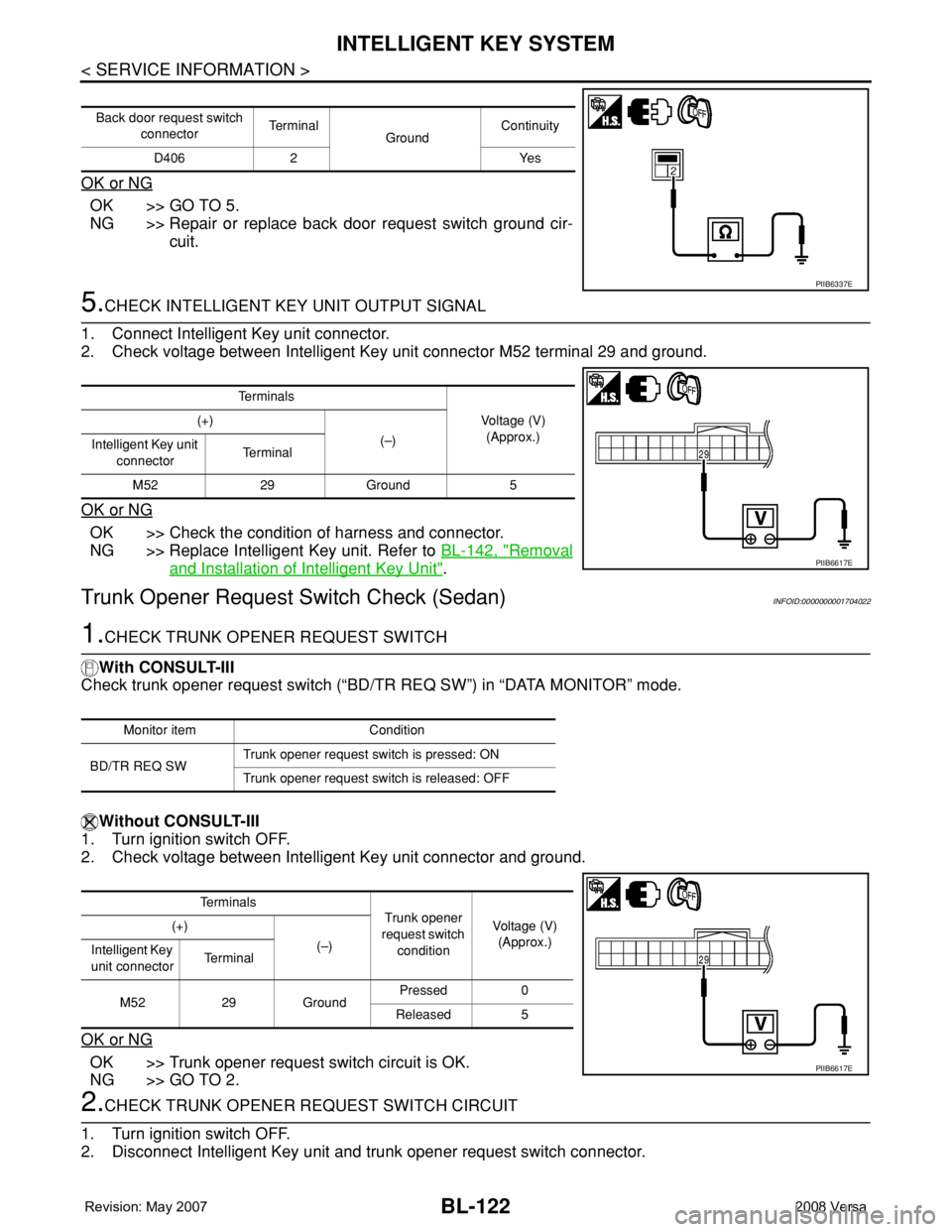
OK or NG
OK >> GO TO 5.
NG >> Repair or replace back door request switch ground cir-
cuit.
5.CHECK INTELLIGENT KEY UNIT OUTPUT SIGNAL
1. Connect Intelligent Key unit connector.
2. Check voltage between Intelligent Key unit connector M52 terminal 29 and ground.
OK or NG
OK >> Check the condition of harness and connector.
NG >> Replace Intelligent Key unit. Refer to BL-142, "
Removal
and Installation of Intelligent Key Unit".
Trunk Opener Request Switch Check (Sedan)INFOID:0000000001704022
1.CHECK TRUNK OPENER REQUEST SWITCH
With CONSULT-III
Check trunk opener request switch (“BD/TR REQ SW”) in “DATA MONITOR” mode.
Without CONSULT-III
1. Turn ignition switch OFF.
2. Check voltage between Intelligent Key unit connector and ground.
OK or NG
OK >> Trunk opener request switch circuit is OK.
NG >> GO TO 2.
2.CHECK TRUNK OPENER REQUEST SWITCH CIRCUIT
1. Turn ignition switch OFF.
2. Disconnect Intelligent Key unit and trunk opener request switch connector.
Back door request switch
connectorTe r m i n a l
GroundContinuity
D406 2 Yes
PIIB6337E
Te r m i n a l s
Voltage (V)
(Approx.) (+)
(–)
Intelligent Key unit
connectorTe r m i n a l
M52 29 Ground 5
PIIB6617E
Monitor item Condition
BD/TR REQ SWTrunk opener request switch is pressed: ON
Trunk opener request switch is released: OFF
Te r m i n a l s
Trunk opener
request switch
conditionVoltage (V)
(Approx.) (+)
(–)
Intelligent Key
unit connectorTe r m i n a l
M52 29 GroundPressed 0
Released 5
PIIB6617E
Page 558 of 2771
BL-124
< SERVICE INFORMATION >
INTELLIGENT KEY SYSTEM
OK or NG
OK >> Check the condition of harness and connector.
NG >> Replace Intelligent Key unit. Refer to BL-142, "
Removal
and Installation of Intelligent Key Unit".
Unlock Sensor CheckINFOID:0000000001704023
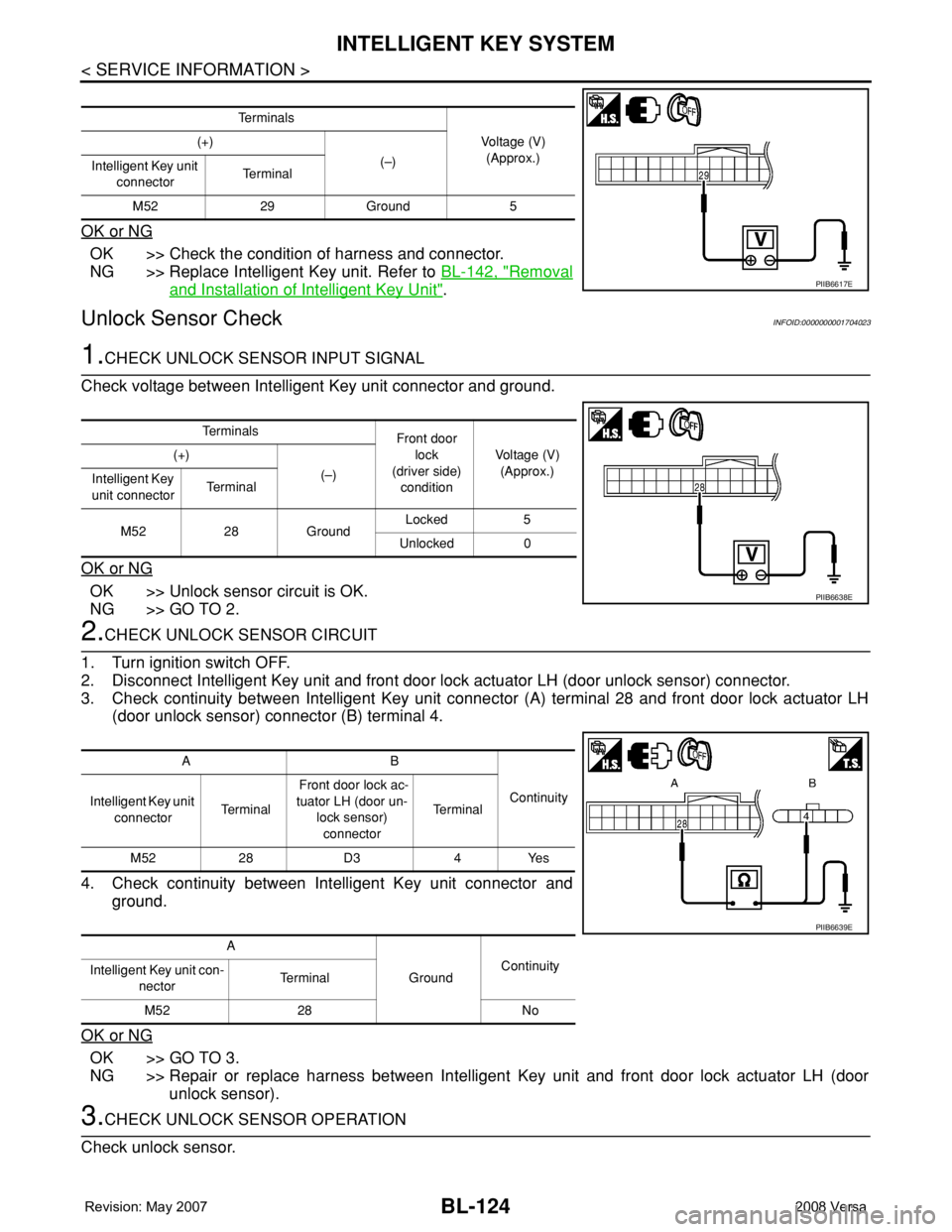
1.CHECK UNLOCK SENSOR INPUT SIGNAL
Check voltage between Intelligent Key unit connector and ground.
OK or NG
OK >> Unlock sensor circuit is OK.
NG >> GO TO 2.
2.CHECK UNLOCK SENSOR CIRCUIT
1. Turn ignition switch OFF.
2. Disconnect Intelligent Key unit and front door lock actuator LH (door unlock sensor) connector.
3. Check continuity between Intelligent Key unit connector (A) terminal 28 and front door lock actuator LH
(door unlock sensor) connector (B) terminal 4.
4. Check continuity between Intelligent Key unit connector and
ground.
OK or NG
OK >> GO TO 3.
NG >> Repair or replace harness between Intelligent Key unit and front door lock actuator LH (door
unlock sensor).
3.CHECK UNLOCK SENSOR OPERATION
Check unlock sensor.
Te r m i n a l s
Voltage (V)
(Approx.) (+)
(–)
Intelligent Key unit
connectorTe r m i n a l
M52 29 Ground 5
PIIB6617E
Te r m i n a l s
Front door
lock
(driver side)
conditionVoltage (V)
(Approx.) (+)
(–)
Intelligent Key
unit connectorTe r m i n a l
M52 28 GroundLocked 5
Unlocked 0
PIIB6638E
AB
Continuity
Intelligent Key unit
connectorTe r m i n a l Front door lock ac-
tuator LH (door un-
lock sensor)
connectorTe r m i n a l
M52 28 D3 4 Yes
A
GroundContinuity
Intelligent Key unit con-
nectorTerminal
M52 28 No
PIIB6639E
Page 561 of 2771
INTELLIGENT KEY SYSTEM
BL-127
< SERVICE INFORMATION >
C
D
E
F
G
H
J
K
L
MA
B
BL
N
O
P
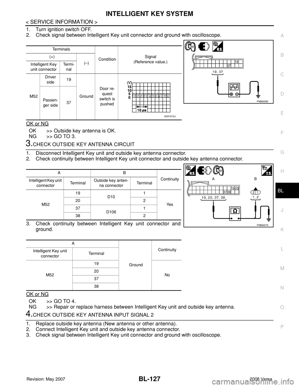
1. Turn ignition switch OFF.
2. Check signal between Intelligent Key unit connector and ground with oscilloscope.
OK or NG
OK >> Outside key antenna is OK.
NG >> GO TO 3.
3.CHECK OUTSIDE KEY ANTENNA CIRCUIT
1. Disconnect Intelligent Key unit and outside key antenna connector.
2. Check continuity between Intelligent Key unit connector and outside key antenna connector.
3. Check continuity between Intelligent Key unit connector and
ground.
OK or NG
OK >> GO TO 4.
NG >> Repair or replace harness between Intelligent Key unit and outside key antenna.
4.CHECK OUTSIDE KEY ANTENNA INPUT SIGNAL 2
1. Replace outside key antenna (New antenna or other antenna).
2. Connect Intelligent Key unit and outside key antenna connector.
3. Check signal between Intelligent Key unit connector and ground with oscilloscope.
Te r m i n a l s
ConditionSignal
(Reference value.) (+)
(–)
Intelligent Key
unit connectorTe r m i -
nal
M52Driver
side19
GroundDoor re-
quest
switch is
pushed Passen-
ger side37
PIIB6626E
SIIA1910J
AB
Continuity
Intelligent Key unit
connectorTe r m i n a lOutside key anten-
na connectorTe r m i n a l
M5219
D101
Ye s 20 2
37
D1061
38 2
A
GroundContinuity
Intelligent Key unit
connectorTe r m i n a l
M5219
No 20
37
38
PIIB6627E
Page 562 of 2771
BL-128
< SERVICE INFORMATION >
INTELLIGENT KEY SYSTEM
OK or NG
OK >> Replace malfunctioning outside key antenna.
NG >> Replace Intelligent Key unit. Refer to BL-142, "
Removal and Installation of Intelligent Key Unit".
Outside Key Antenna (Rear Bumper) CheckINFOID:0000000001704026
1.CHECK REAR BUMPER ANTENNA FUNCTION
With CONSULT-III
1. Check the operation with (“ANTENNA”) in the ACTIVE TEST.
2. Touch “BD/TR ANT” on screen.
3. Carry the Intelligent Key into the antenna detection area.
Do the hazard lamps flash?
Yes >> Rear bumper antenna is OK.
No >> GO TO 2.
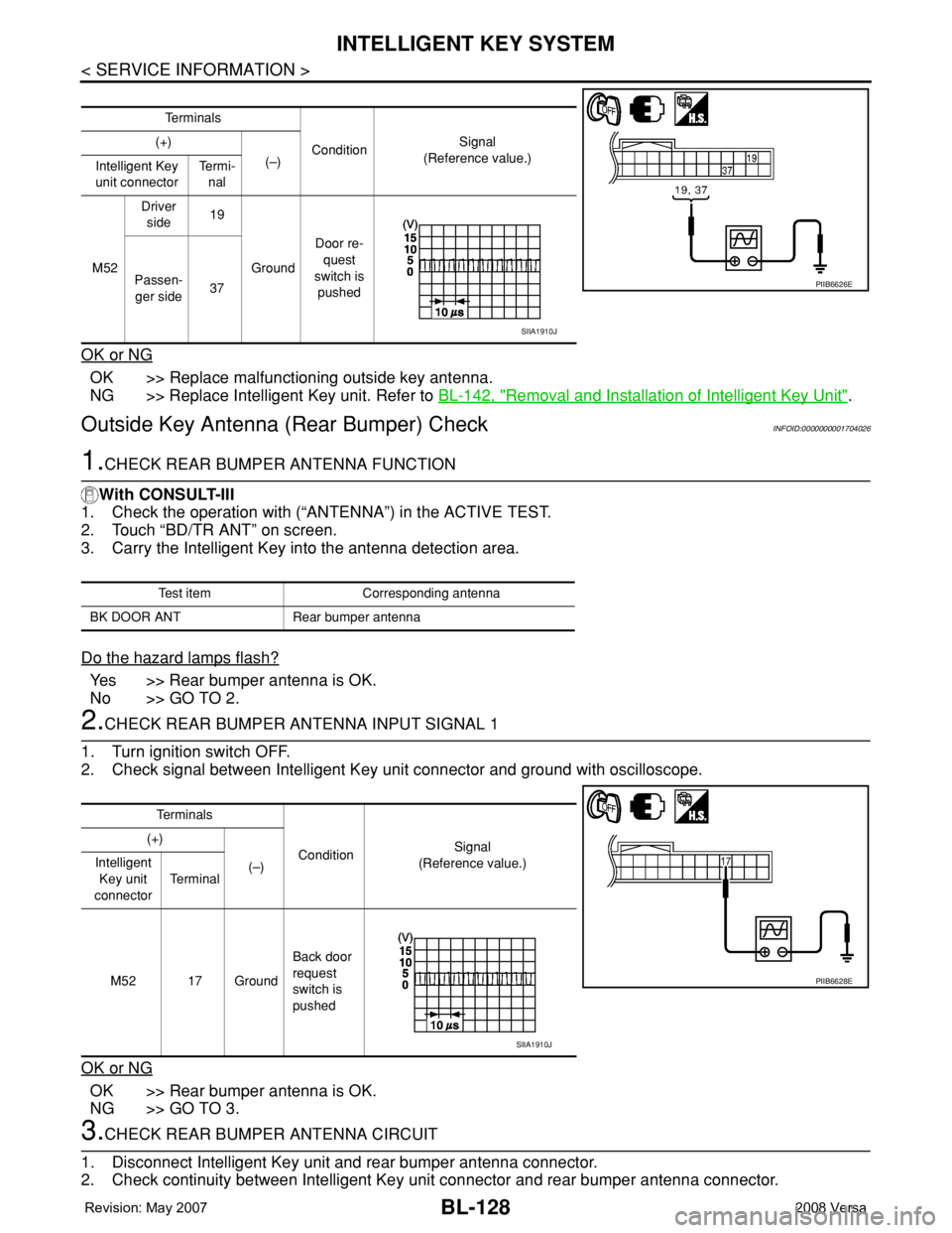
2.CHECK REAR BUMPER ANTENNA INPUT SIGNAL 1
1. Turn ignition switch OFF.
2. Check signal between Intelligent Key unit connector and ground with oscilloscope.
OK or NG
OK >> Rear bumper antenna is OK.
NG >> GO TO 3.
3.CHECK REAR BUMPER ANTENNA CIRCUIT
1. Disconnect Intelligent Key unit and rear bumper antenna connector.
2. Check continuity between Intelligent Key unit connector and rear bumper antenna connector.
Te r m i n a l s
ConditionSignal
(Reference value.) (+)
(–)
Intelligent Key
unit connectorTe r m i -
nal
M52Driver
side19
GroundDoor re-
quest
switch is
pushed Passen-
ger side37
PIIB6626E
SIIA1910J
Test item Corresponding antenna
BK DOOR ANT Rear bumper antenna
Te r m i n a l s
ConditionSignal
(Reference value.) (+)
(–) Intelligent
Key unit
connectorTe r m i n a l
M52 17 GroundBack door
request
switch is
pushed
PIIB6628E
SIIA1910J
Page 563 of 2771
INTELLIGENT KEY SYSTEM
BL-129
< SERVICE INFORMATION >
C
D
E
F
G
H
J
K
L
MA
B
BL
N
O
P
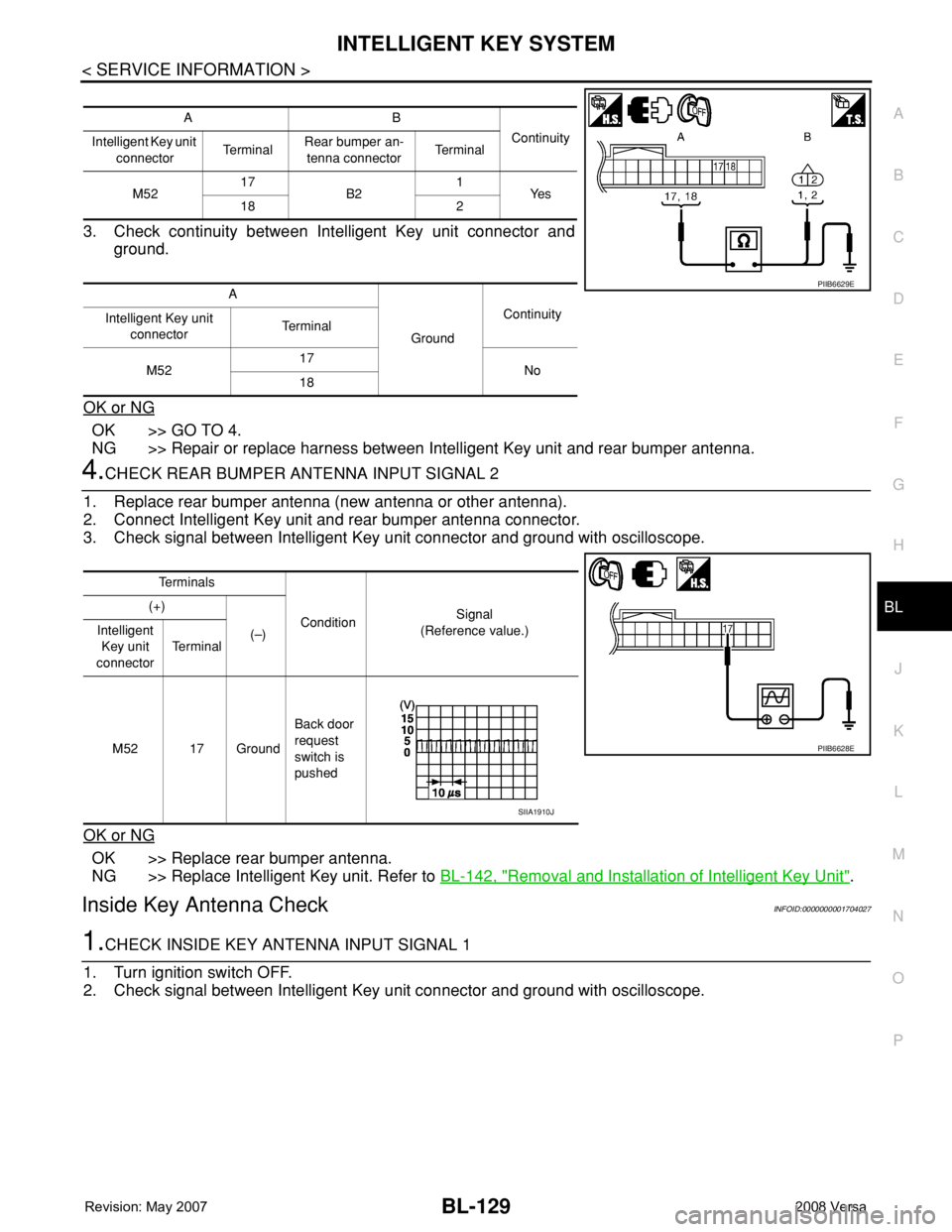
3. Check continuity between Intelligent Key unit connector and
ground.
OK or NG
OK >> GO TO 4.
NG >> Repair or replace harness between Intelligent Key unit and rear bumper antenna.
4.CHECK REAR BUMPER ANTENNA INPUT SIGNAL 2
1. Replace rear bumper antenna (new antenna or other antenna).
2. Connect Intelligent Key unit and rear bumper antenna connector.
3. Check signal between Intelligent Key unit connector and ground with oscilloscope.
OK or NG
OK >> Replace rear bumper antenna.
NG >> Replace Intelligent Key unit. Refer to BL-142, "
Removal and Installation of Intelligent Key Unit".
Inside Key Antenna CheckINFOID:0000000001704027
1.CHECK INSIDE KEY ANTENNA INPUT SIGNAL 1
1. Turn ignition switch OFF.
2. Check signal between Intelligent Key unit connector and ground with oscilloscope.
AB
Continuity
Intelligent Key unit
connectorTe r m i n a lRear bumper an-
tenna connectorTe r m i n a l
M5217
B21
Ye s
18 2
A
GroundContinuity
Intelligent Key unit
connectorTe r m i n a l
M5217
No
18
PIIB6629E
Te r m i n a l s
ConditionSignal
(Reference value.) (+)
(–) Intelligent
Key unit
connectorTe r m i n a l
M52 17 GroundBack door
request
switch is
pushed
PIIB6628E
SIIA1910J
Page 565 of 2771
INTELLIGENT KEY SYSTEM
BL-131
< SERVICE INFORMATION >
C
D
E
F
G
H
J
K
L
MA
B
BL
N
O
P
OK or NG
OK >> Replace malfunction inside key antenna.
NG >> Replace Intelligent Key unit.
Steering Lock Solenoid CheckINFOID:0000000001704028
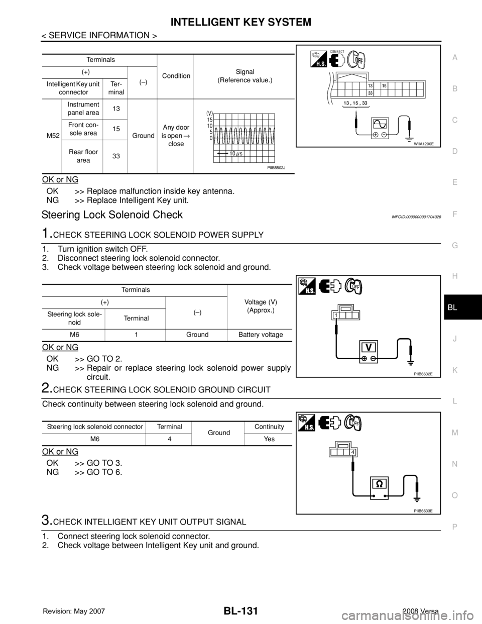
1.CHECK STEERING LOCK SOLENOID POWER SUPPLY
1. Turn ignition switch OFF.
2. Disconnect steering lock solenoid connector.
3. Check voltage between steering lock solenoid and ground.
OK or NG
OK >> GO TO 2.
NG >> Repair or replace steering lock solenoid power supply
circuit.
2.CHECK STEERING LOCK SOLENOID GROUND CIRCUIT
Check continuity between steering lock solenoid and ground.
OK or NG
OK >> GO TO 3.
NG >> GO TO 6.
3.CHECK INTELLIGENT KEY UNIT OUTPUT SIGNAL
1. Connect steering lock solenoid connector.
2. Check voltage between Intelligent Key unit and ground.
Te r m i n a l s
ConditionSignal
(Reference value.) (+)
(–)
Intelligent Key unit
connectorTe r -
minal
M52Instrument
panel area13
GroundAny door
is open →
close Front con-
sole area15
Rear floor
area33
WIIA1200E
PIIB5502J
Te r m i n a l s
Voltage (V)
(Approx.) (+)
(–)
Steering lock sole-
noidTe r m i n a l
M6 1 Ground Battery voltage
PIIB6632E
Steering lock solenoid connector Terminal
GroundContinuity
M6 4 Yes
PIIB6633E
Page 568 of 2771
BL-134
< SERVICE INFORMATION >
INTELLIGENT KEY SYSTEM
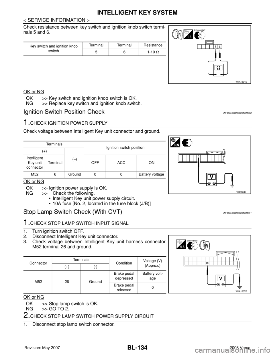
Check resistance between key switch and ignition knob switch termi-
nals 5 and 6.
OK or NG
OK >> Key switch and ignition knob switch is OK.
NG >> Replace key switch and ignition knob switch.
Ignition Switch Position CheckINFOID:0000000001704030
1.CHECK IGNITION POWER SUPPLY
Check voltage between Intelligent Key unit connector and ground.
OK or NG
OK >> Ignition power supply is OK.
NG >> Check the following.
• Intelligent Key unit power supply circuit.
• 10A fuse [No. 2, located in the fuse block (J/B)]
Stop Lamp Switch Check (With CVT)INFOID:0000000001704031
1.CHECK STOP LAMP SWITCH INPUT SIGNAL
1. Turn ignition switch OFF.
2. Disconnect Intelligent Key unit connector.
3. Check voltage between Intelligent Key unit harness connector
M52 terminal 26 and ground.
OK or NG
OK >> Stop lamp switch is OK.
NG >> GO TO 2.
2.CHECK STOP LAMP SWITCH POWER SUPPLY CIRCUIT
1. Disconnect stop lamp switch connector.
Key switch and ignition knob
switchTerminal Terminal Resistance
561-10 Ω
WIIA1301E
Te r m i n a l s
Ignition switch position
(+)
(–) Intelligent
Key unit
connectorTerminal OFF ACC ON
M52 6 Ground 0 0 Battery voltage
PIIB6884E
ConnectorTe r m i n a l s
ConditionVoltage (V)
(Approx.)
(+) (-)
M52 26 GroundBrake pedal
depressedBattery volt-
age
Brake pedal
released0
WIIA1207E
Page 569 of 2771
INTELLIGENT KEY SYSTEM
BL-135
< SERVICE INFORMATION >
C
D
E
F
G
H
J
K
L
MA
B
BL
N
O
P
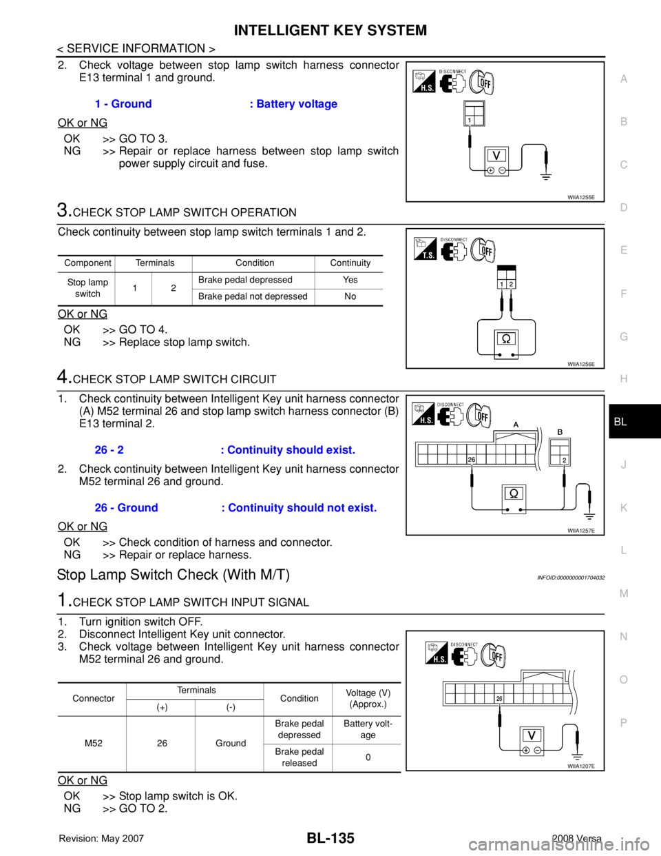
2. Check voltage between stop lamp switch harness connector
E13 terminal 1 and ground.
OK or NG
OK >> GO TO 3.
NG >> Repair or replace harness between stop lamp switch
power supply circuit and fuse.
3.CHECK STOP LAMP SWITCH OPERATION
Check continuity between stop lamp switch terminals 1 and 2.
OK or NG
OK >> GO TO 4.
NG >> Replace stop lamp switch.
4.CHECK STOP LAMP SWITCH CIRCUIT
1. Check continuity between Intelligent Key unit harness connector
(A) M52 terminal 26 and stop lamp switch harness connector (B)
E13 terminal 2.
2. Check continuity between Intelligent Key unit harness connector
M52 terminal 26 and ground.
OK or NG
OK >> Check condition of harness and connector.
NG >> Repair or replace harness.
Stop Lamp Switch Check (With M/T)INFOID:0000000001704032
1.CHECK STOP LAMP SWITCH INPUT SIGNAL
1. Turn ignition switch OFF.
2. Disconnect Intelligent Key unit connector.
3. Check voltage between Intelligent Key unit harness connector
M52 terminal 26 and ground.
OK or NG
OK >> Stop lamp switch is OK.
NG >> GO TO 2.1 - Ground : Battery voltage
WIIA1255E
Component Terminals Condition Continuity
Stop lamp
switch12Brake pedal depressed Yes
Brake pedal not depressed No
WIIA1256E
26 - 2 : Continuity should exist.
26 - Ground : Continuity should not exist.
WIIA1257E
ConnectorTe r m i n a l s
ConditionVoltage (V)
(Approx.)
(+) (-)
M52 26 GroundBrake pedal
depressedBattery volt-
age
Brake pedal
released0
WIIA1207E