2008 NISSAN LATIO turn signal
[x] Cancel search: turn signalPage 640 of 2771
BL-206
< SERVICE INFORMATION >
VEHICLE SECURITY (THEFT WARNING) SYSTEM
OK >> GO TO 3.
NG >> Repair or replace harness.
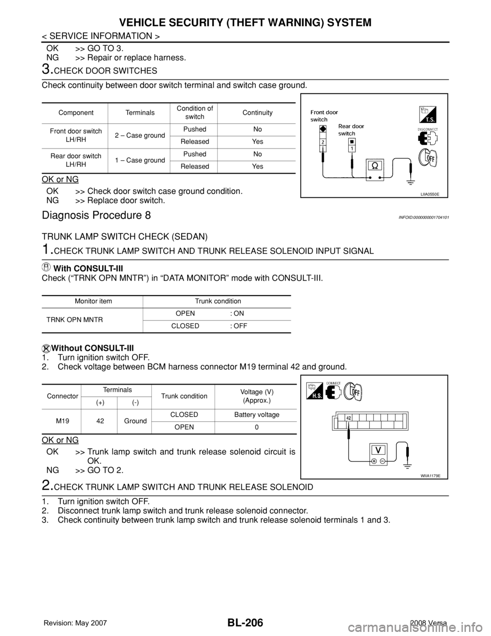
3.CHECK DOOR SWITCHES
Check continuity between door switch terminal and switch case ground.
OK or NG
OK >> Check door switch case ground condition.
NG >> Replace door switch.
Diagnosis Procedure 8INFOID:0000000001704101
TRUNK LAMP SWITCH CHECK (SEDAN)
1.CHECK TRUNK LAMP SWITCH AND TRUNK RELEASE SOLENOID INPUT SIGNAL
With CONSULT-III
Check (“TRNK OPN MNTR”) in “DATA MONITOR” mode with CONSULT-III.
Without CONSULT-III
1. Turn ignition switch OFF.
2. Check voltage between BCM harness connector M19 terminal 42 and ground.
OK or NG
OK >> Trunk lamp switch and trunk release solenoid circuit is
OK.
NG >> GO TO 2.
2.CHECK TRUNK LAMP SWITCH AND TRUNK RELEASE SOLENOID
1. Turn ignition switch OFF.
2. Disconnect trunk lamp switch and trunk release solenoid connector.
3. Check continuity between trunk lamp switch and trunk release solenoid terminals 1 and 3.
Component TerminalsCondition of
switchContinuity
Front door switch
LH/RH2 – Case groundPushed No
Released Yes
Rear door switch
LH/RH1 – Case groundPushed No
Released Yes
LIIA0550E
Monitor item Trunk condition
TRNK OPN MNTROPEN : ON
CLOSED : OFF
ConnectorTe r m i n a l s
Trunk conditionVoltage (V)
(Approx.)
(+) (-)
M19 42 GroundCLOSED Battery voltage
OPEN 0
WIIA1179E
Page 642 of 2771
BL-208
< SERVICE INFORMATION >
VEHICLE SECURITY (THEFT WARNING) SYSTEM
• When key inserted in trunk key cylinder is turned to FULL STROKE:
• When key is removed from the trunk key cylinder:
Without CONSULT-III
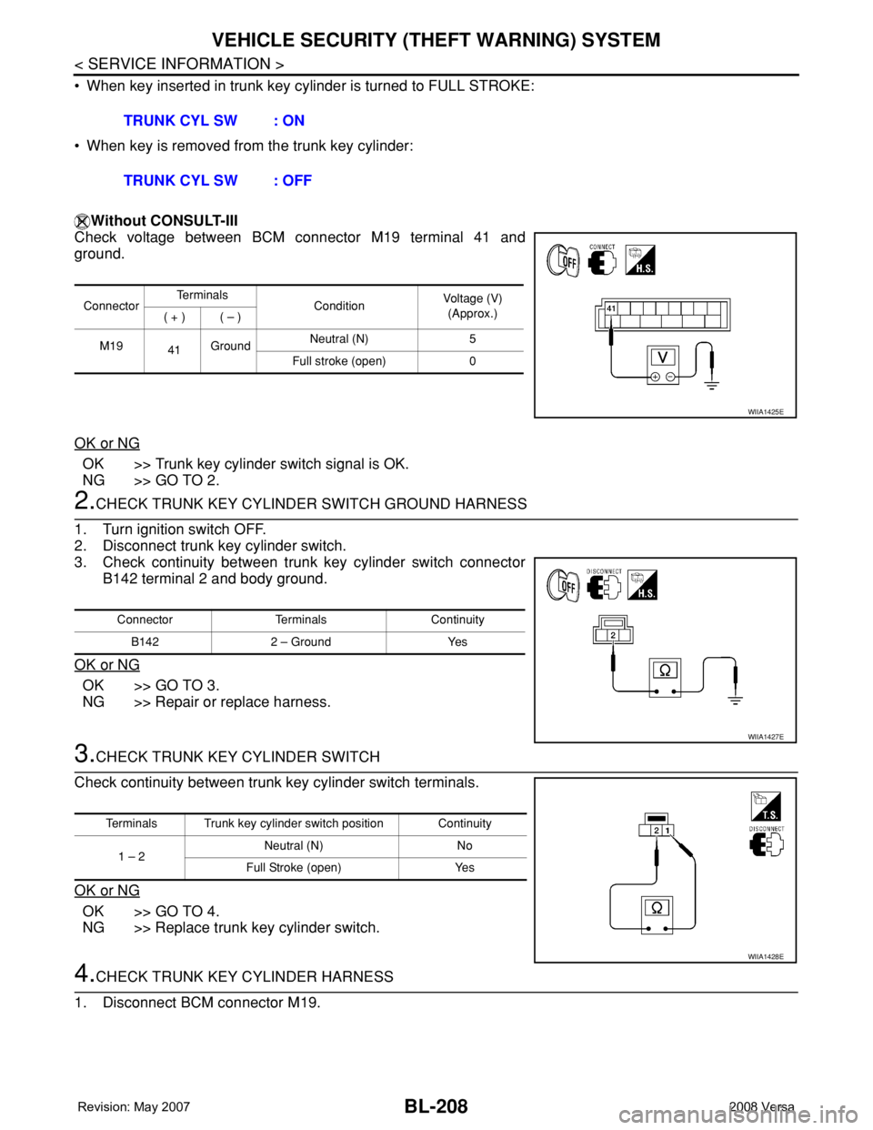
Check voltage between BCM connector M19 terminal 41 and
ground.
OK or NG
OK >> Trunk key cylinder switch signal is OK.
NG >> GO TO 2.
2.CHECK TRUNK KEY CYLINDER SWITCH GROUND HARNESS
1. Turn ignition switch OFF.
2. Disconnect trunk key cylinder switch.
3. Check continuity between trunk key cylinder switch connector
B142 terminal 2 and body ground.
OK or NG
OK >> GO TO 3.
NG >> Repair or replace harness.
3.CHECK TRUNK KEY CYLINDER SWITCH
Check continuity between trunk key cylinder switch terminals.
OK or NG
OK >> GO TO 4.
NG >> Replace trunk key cylinder switch.
4.CHECK TRUNK KEY CYLINDER HARNESS
1. Disconnect BCM connector M19.TRUNK CYL SW : ON
TRUNK CYL SW : OFF
ConnectorTe r m i n a l s
ConditionVoltage (V)
(Approx.)
( + ) ( – )
M19
41GroundNeutral (N) 5
Full stroke (open) 0
WIIA1425E
Connector Terminals Continuity
B142 2 – Ground Yes
WIIA1427E
Terminals Trunk key cylinder switch position Continuity
1 – 2 Neutral (N) No
Full Stroke (open) Yes
WIIA1428E
Page 648 of 2771
BL-214
< SERVICE INFORMATION >
NATS (NISSAN ANTI-THEFT SYSTEM)
1. Turn ignition switch OFF.
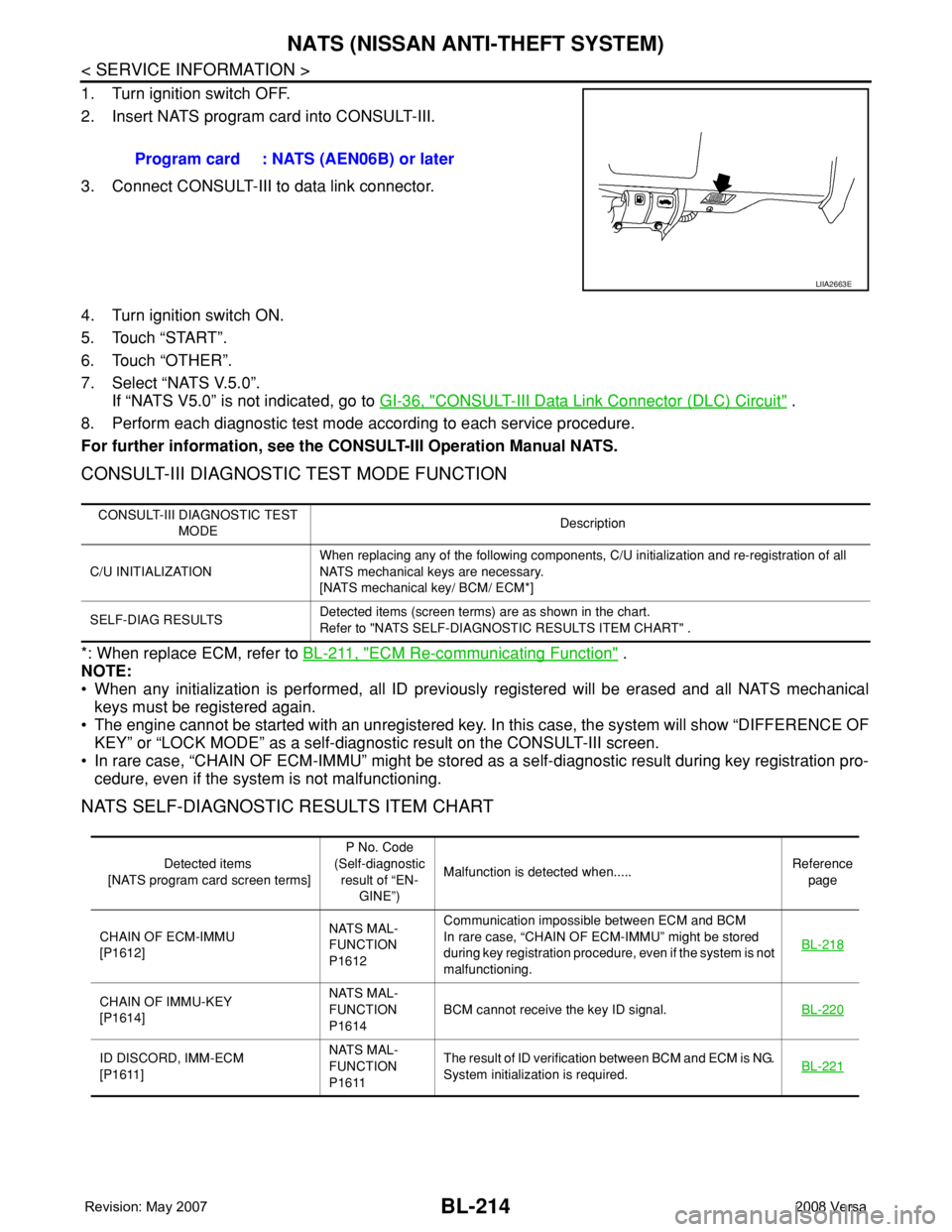
2. Insert NATS program card into CONSULT-III.
3. Connect CONSULT-III to data link connector.
4. Turn ignition switch ON.
5. Touch “START”.
6. Touch “OTHER”.
7. Select “NATS V.5.0”.
If “NATS V5.0” is not indicated, go to GI-36, "
CONSULT-III Data Link Connector (DLC) Circuit" .
8. Perform each diagnostic test mode according to each service procedure.
For further information, see the CONSULT-III Operation Manual NATS.
CONSULT-III DIAGNOSTIC TEST MODE FUNCTION
*: When replace ECM, refer to BL-211, "ECM Re-communicating Function" .
NOTE:
• When any initialization is performed, all ID previously registered will be erased and all NATS mechanical
keys must be registered again.
• The engine cannot be started with an unregistered key. In this case, the system will show “DIFFERENCE OF
KEY” or “LOCK MODE” as a self-diagnostic result on the CONSULT-III screen.
• In rare case, “CHAIN OF ECM-IMMU” might be stored as a self-diagnostic result during key registration pro-
cedure, even if the system is not malfunctioning.
NATS SELF-DIAGNOSTIC RESULTS ITEM CHART
Program card : NATS (AEN06B) or later
LIIA2663E
CONSULT-III DIAGNOSTIC TEST
MODEDescription
C/U INITIALIZATIONWhen replacing any of the following components, C/U initialization and re-registration of all
NATS mechanical keys are necessary.
[NATS mechanical key/ BCM/ ECM*]
SELF-DIAG RESULTSDetected items (screen terms) are as shown in the chart.
Refer to "NATS SELF-DIAGNOSTIC RESULTS ITEM CHART" .
Detected items
[NATS program card screen terms]P No. Code
(Self-diagnostic
result of “EN-
GINE”)Malfunction is detected when.....Reference
page
CHAIN OF ECM-IMMU
[P1612]NATS MAL-
FUNCTION
P1612Communication impossible between ECM and BCM
In rare case, “CHAIN OF ECM-IMMU” might be stored
during key registration procedure, even if the system is not
malfunctioning.BL-218
CHAIN OF IMMU-KEY
[P1614]NATS MAL-
FUNCTION
P1614BCM cannot receive the key ID signal.BL-220
ID DISCORD, IMM-ECM
[P1611]NATS MAL-
FUNCTION
P1611The result of ID verification between BCM and ECM is NG.
System initialization is required.BL-221
Page 653 of 2771
NATS (NISSAN ANTI-THEFT SYSTEM)
BL-219
< SERVICE INFORMATION >
C
D
E
F
G
H
J
K
L
MA
B
BL
N
O
P
In rare case, “CHAIN OF ECM-IMMU” might be stored during key registration procedure, even if the system is
not malfunctioning.
Is
“CHAIN OF ECM-IMMU” displayed?
Yes >> GO TO 2.
No >> GO TO BL-217, "
Trouble Diagnosis" .
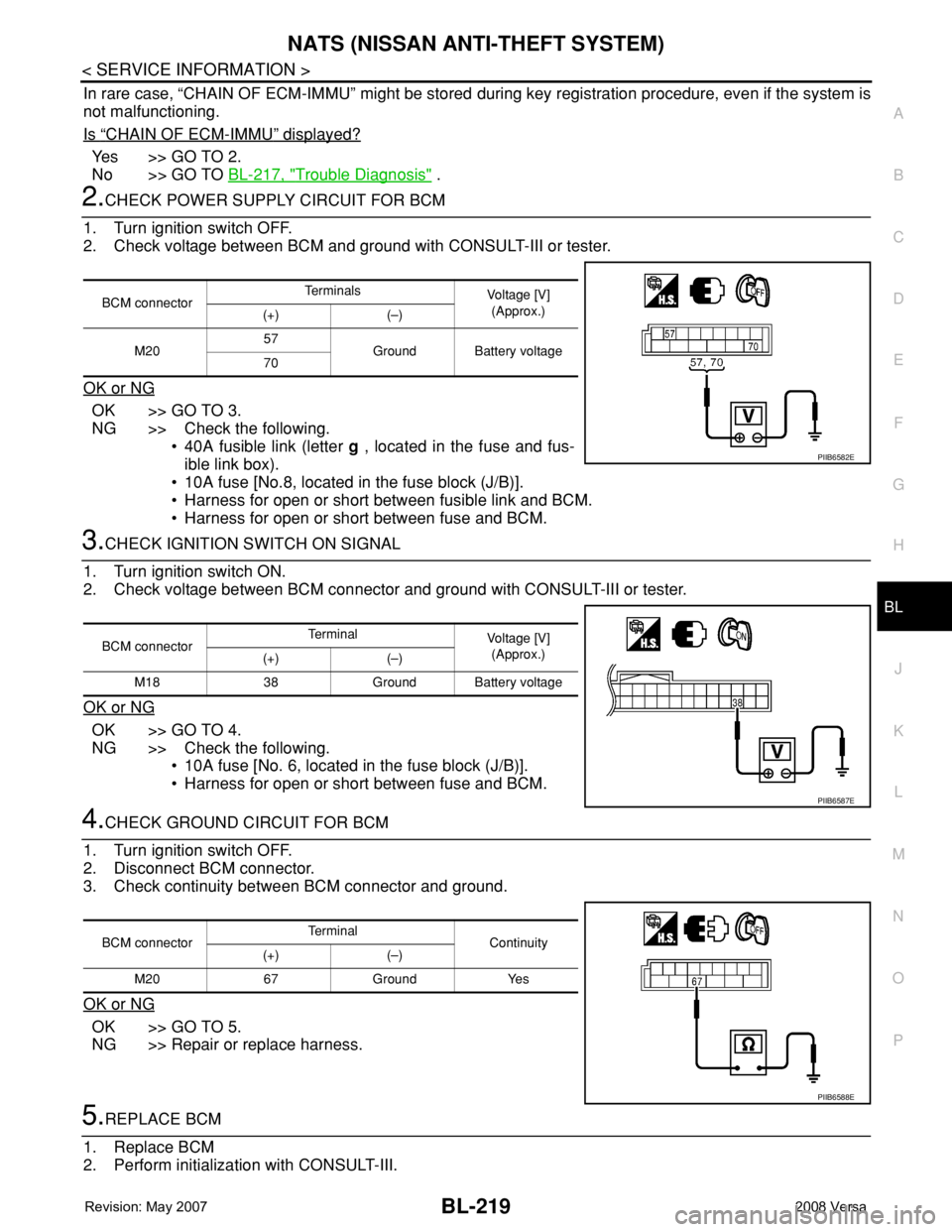
2.CHECK POWER SUPPLY CIRCUIT FOR BCM
1. Turn ignition switch OFF.
2. Check voltage between BCM and ground with CONSULT-III or tester.
OK or NG
OK >> GO TO 3.
NG >> Check the following.
• 40A fusible link (letter g , located in the fuse and fus-
ible link box).
• 10A fuse [No.8, located in the fuse block (J/B)].
• Harness for open or short between fusible link and BCM.
• Harness for open or short between fuse and BCM.
3.CHECK IGNITION SWITCH ON SIGNAL
1. Turn ignition switch ON.
2. Check voltage between BCM connector and ground with CONSULT-III or tester.
OK or NG
OK >> GO TO 4.
NG >> Check the following.
• 10A fuse [No. 6, located in the fuse block (J/B)].
• Harness for open or short between fuse and BCM.
4.CHECK GROUND CIRCUIT FOR BCM
1. Turn ignition switch OFF.
2. Disconnect BCM connector.
3. Check continuity between BCM connector and ground.
OK or NG
OK >> GO TO 5.
NG >> Repair or replace harness.
5.REPLACE BCM
1. Replace BCM
2. Perform initialization with CONSULT-III.
BCM connectorTe r m i n a l s
Voltage [V]
(Approx.)
(+) (–)
M2057
Ground Battery voltage
70
PIIB6582E
BCM connectorTerminal
Voltage [V]
(Approx.)
(+) (–)
M18 38 Ground Battery voltage
PIIB6587E
BCM connectorTerminal
Continuity
(+) (–)
M20 67 Ground Yes
PIIB6588E
Page 654 of 2771
BL-220
< SERVICE INFORMATION >
NATS (NISSAN ANTI-THEFT SYSTEM)
For initialization, refer to “CONSULT-III Operation Manual NATS”.
Does the engine start?
Yes >> BCM is malfunctioning.
• Replace BCM. Refer to BCS-18, "
Removal and Installation of BCM" .
• Perform initialization with CONSULT-III
• For initialization, refer to “CONSULT-III Operation Manual NATS”
No >> ECM is malfunctioning.
• Replace ECM.
• Perform initialization or re-communicating function
• For initialization, refer to “CONSULT-III Operation Manual NATS”
• For re-communicating function, refer to BL-211, "
ECM Re-communicating Function"
Diagnosis Procedure 2INFOID:0000000001704113
Self-diagnostic results:
“CHAIN OF IMMU-KEY” displayed on CONSULT-III screen
1.CONFIRM SELF-DIAGNOSTIC RESULTS
Confirm SELF-DIAGNOSTIC RESULTS “CHAIN OF IMMU-KEY” displayed on CONSULT-III screen.
Is
“CHAIN OF IMMU-KEY” displayed?
Ye s > > G O T O 2 .
No >> GO TO BL-217, "
Trouble Diagnosis" .
2.CHECK NATS ANTENNA AMP. INSTALLATION
Check NATS antenna amp. installation. Refer to BL-224, "
How to Replace NATS Antenna Amp" .
OK or NG
OK >> GO TO 3.
NG >> Reinstall NATS antenna amp. correctly.
3.CHECK NATS IGNITION KEY ID CHIP
Start engine with another registered NATS ignition key.
Does the engine start?
Yes >> Ignition key ID chip is malfunctioning.
• Replace the ignition key
• Perform initialization with CONSULT-III
For initialization, refer to “CONSULT-III Operation Manual NATS”
No >> GO TO 4.
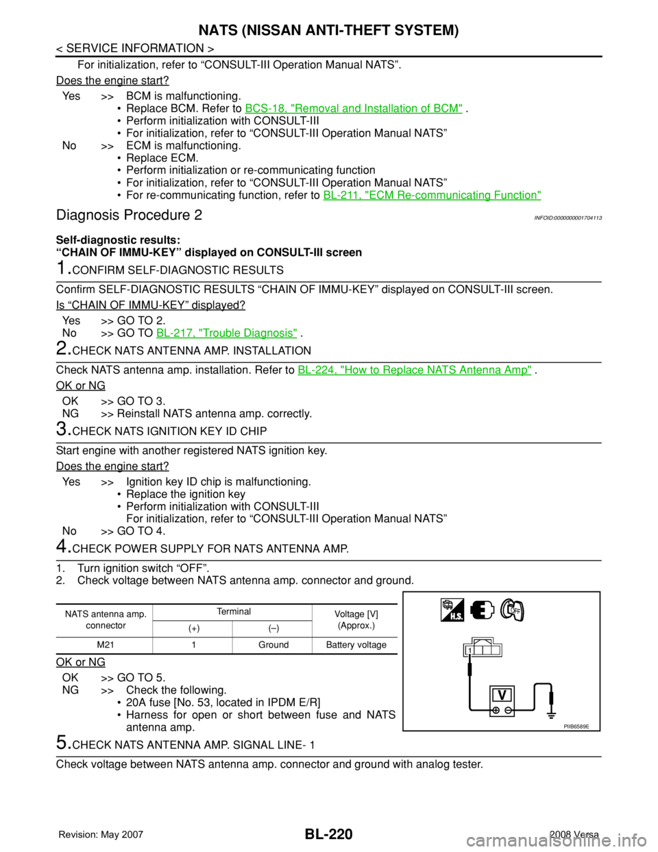
4.CHECK POWER SUPPLY FOR NATS ANTENNA AMP.
1. Turn ignition switch “OFF”.
2. Check voltage between NATS antenna amp. connector and ground.
OK or NG
OK >> GO TO 5.
NG >> Check the following.
• 20A fuse [No. 53, located in IPDM E/R]
• Harness for open or short between fuse and NATS
antenna amp.
5.CHECK NATS ANTENNA AMP. SIGNAL LINE- 1
Check voltage between NATS antenna amp. connector and ground with analog tester.
NATS antenna amp.
connectorTe r m i n a l
Voltage [V]
(Approx.)
(+) (–)
M21 1 Ground Battery voltage
PIIB6589E
Page 655 of 2771
NATS (NISSAN ANTI-THEFT SYSTEM)
BL-221
< SERVICE INFORMATION >
C
D
E
F
G
H
J
K
L
MA
B
BL
N
O
P
OK or NG
OK >> GO TO 6.
NG >> • Check harness for open or short between NATS antenna amp. and BCM.
NOTE:
If harness is OK, replace BCM, perform initialization with CONSULT-III. For initialization, refer to
“CONSULT-III Operation Manual NATS”.
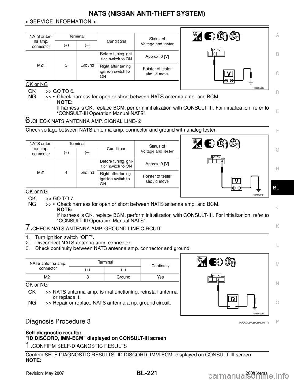
6.CHECK NATS ANTENNA AMP. SIGNAL LINE- 2
Check voltage between NATS antenna amp. connector and ground with analog tester.
OK or NG
OK >> GO TO 7.
NG >> • Check harness for open or short between NATS antenna amp. and BCM.
NOTE:
If harness is OK, replace BCM, perform initialization with CONSULT-III. For initialization, refer to
“CONSULT-III Operation Manual NATS”.
7.CHECK NATS ANTENNA AMP. GROUND LINE CIRCUIT
1. Turn ignition switch “OFF”.
2. Disconnect NATS antenna amp. connector.
3. Check continuity between NATS antenna amp. connector and ground.
OK or NG
OK >> NATS antenna amp. is malfunctioning, reinstall antenna
or replace it.
NG >> Repair or replace NATS antenna amp. ground circuit.
Diagnosis Procedure 3INFOID:0000000001704114
Self-diagnostic results:
“ID DISCORD, IMM-ECM” displayed on CONSULT-III screen
1.CONFIRM SELF-DIAGNOSTIC RESULTS
Confirm SELF-DIAGNOSTIC RESULTS “ID DISCORD, IMM-ECM” displayed on CONSULT-III screen.
NOTE:
NATS anten-
na amp.
connectorTe r m i n a l
ConditionsStatus of
Voltage and tester
(+) (–)
M21 2 GroundBefore tuning igni-
tion switch to ONApprox. 0 [V]
Right after tuning
ignition switch to
ONPointer of tester
should move
PIIB6590E
NATS anten-
na amp.
connectorTe r m i n a l
ConditionsStatus of
Voltage and tester
(+) (–)
M21 4 GroundBefore tuning igni-
tion switch to ONApprox. 0 [V]
Right after tuning
ignition switch to
ONPointer of tester
should move
PIIB6591E
NATS antenna amp.
connectorTe r m i n a l
Continuity
(+) (–)
M21 3 Ground Yes
PIIB6592E
Page 782 of 2771
![NISSAN LATIO 2008 Service Repair Manual TROUBLE DIAGNOSIS
BRC-17
< SERVICE INFORMATION >[ABS]
C
D
E
G
H
I
J
K
L
MA
B
BRC
N
O
P
• If ABS actuator and electric unit (control unit) connection is loose, tighten the piping to the specified
tor NISSAN LATIO 2008 Service Repair Manual TROUBLE DIAGNOSIS
BRC-17
< SERVICE INFORMATION >[ABS]
C
D
E
G
H
I
J
K
L
MA
B
BRC
N
O
P
• If ABS actuator and electric unit (control unit) connection is loose, tighten the piping to the specified
tor](/manual-img/5/57360/w960_57360-781.png)
TROUBLE DIAGNOSIS
BRC-17
< SERVICE INFORMATION >[ABS]
C
D
E
G
H
I
J
K
L
MA
B
BRC
N
O
P
• If ABS actuator and electric unit (control unit) connection is loose, tighten the piping to the specified
torque and recheck for leaks.
• If there is damage to the connection flare nut or ABS actuator and electric unit (control unit) threads,
replace the damaged part and recheck for leaks.
• When there is fluid leaking or seeping from a fluid connection, use a clean cloth to wipe off the fluid and
recheck for leaks. If fluid is still seeping out, replace the damaged part. If the fluid is leaking at the ABS
actuator and electric unit (control unit), replace the ABS actuator and electric unit (control unit) assem-
bly.
CAUTION:
The ABS actuator and electric unit (control unit) cannot be disassembled and must be replaced
as an assembly.
3. Check the brake pads for excessive wear.
POWER SYSTEM TERMINAL LOOSENESS AND BATTERY INSPECTION
Make sure the battery positive cable, negative cable and ground connection are not loose. In addition, make
sure the battery is sufficiently charged.
ABS WARNING LAMP INSPECTION
1. Make sure ABS warning lamp turns on for approximately 2 seconds when the ignition switch is turned ON.
If it does not, check CAN communications. If there are no errors with the CAN communication system,
replace the combination meter. Refer to IP-11, "
Removal and Installation".
2. Make sure the lamp turns off approximately 2 seconds after the ignition switch is turned ON. If the lamp
does not turn off, conduct self-diagnosis of ABS actuator and electric unit (control unit). If no malfunctions
are detected in self-diagnosis, replace combination meter. Refer to IP-11, "
Removal and Installation".
3. After conducting the self-diagnosis, be sure to erase the error memory. Refer to BRC-18, "
CONSULT-III
Function (ABS)".
Warning Lamp and Indicator TimingINFOID:0000000001703836
Note 1: Brake warning lamp will turn on when the parking brake is applied or when the brake fluid level is low.
x: ON
–: OFF
Control Unit Input/Output Signal StandardINFOID:0000000001703837
REFERENCE VALUE FROM CONSULT-III
CAUTION:
The display shows the control unit calculation data, so a normal value might be displayed even in the
event the output circuit (harness) is open or short circuited.
ConditionABS
warning lampBRAKE
warning lamp
[Note 1]Remarks
When the ignition switch is OFF – – –
After the ignition switch is turned ON for approx. 1
second××–
After the ignition switch is turned ON for approx. 2
seconds––Lamp goes off approx. 2 seconds after the
engine is started.
ABS malfunction×––
EBD malfunction××–
Page 783 of 2771
![NISSAN LATIO 2008 Service Repair Manual BRC-18
< SERVICE INFORMATION >[ABS]
TROUBLE DIAGNOSIS
Note 1: Confirm tire pressure is normal.
Note 2: ON/OFF timing of ABS warning lamp
ON: For approximately 2 seconds after ignition switch is turned NISSAN LATIO 2008 Service Repair Manual BRC-18
< SERVICE INFORMATION >[ABS]
TROUBLE DIAGNOSIS
Note 1: Confirm tire pressure is normal.
Note 2: ON/OFF timing of ABS warning lamp
ON: For approximately 2 seconds after ignition switch is turned](/manual-img/5/57360/w960_57360-782.png)
BRC-18
< SERVICE INFORMATION >[ABS]
TROUBLE DIAGNOSIS
Note 1: Confirm tire pressure is normal.
Note 2: ON/OFF timing of ABS warning lamp
ON: For approximately 2 seconds after ignition switch is turned ON, or when a malfunction is detected.
OFF: Approximately 2 seconds after ignition switch is turned ON (when system is in normal operation).
CONSULT-III Function (ABS)INFOID:0000000001703838
CONSULT-III can display each diagnostic item using the diagnostic test modes shown following.
Monitor item Display contentData monitor
Note: Error inspection
checklist
ConditionReference value in
normal operation
FR RH SENSOR
FR LH SENSOR
RR RH SENSOR
RR LH SENSORWheel speedVehicle stopped 0 [km/h (MPH)]
BRC-24, "
Wheel Sensor
System"Vehicle running (Note 1)Almost in accor-
dance with speed-
ometer display
(within ±10%)
BATTERY VOLTBattery voltage sup-
plied to ABS actuator
and electric unit (con-
trol unit)Ignition switch ON 10 to 16VBRC-27, "
ABS Control
Unit Power and Ground
Systems Inspection"
STOP LAMP SWStop lamp switch oper-
ationBrake pedal depressed ON
—
Brake pedal not depressed OFF
ABS WARN LAMPABS warning lamp ON
condition (Note 2)ABS warning lamp ON ON
BRC-16, "
Basic Inspec-
tion"ABS warning lamp OFF OFF
MOTOR RELAYOperation status of mo-
tor and motor relayIgnition switch ON or running
(ABS not activated)OFF
BRC-26, "
Actuator Motor,
Motor Relay, and Circuit
Inspection"Ignition switch ON or engine
running (ABS activated)ON
ACTUATOR RLYActuator relay opera-
tion statusVehicle stopped (Ignition
switch ON)OFF
BRC-26, "
Actuator Motor,
Motor Relay, and Circuit
Inspection"Vehicle stopped (Engine run-
ning)ON
FR LH IN SOL
FR LH OUT SOL
FR RH IN SOL
FR RH OUT SOL
RR RH IN SOL
RR RH OUT SOL
RR LH IN SOL
RR LH OUT SOLSolenoid valve opera-
tionActuator (solenoid) is active
(“ACTIVE TEST” with CON-
SULT-III) or actuator relay is in-
active (in fail-safe mode).ON
BRC-25, "
Solenoid Valve
System Inspection"When actuator (solenoid) is not
active and actuator relay is ac-
tive (ignition switch ON).OFF
ABS SIGNAL
EBD SIGNALSignal statusABS active
EBD activeON
ABS system
EBD system
ABS not active
EBD not activeOFF
ABS FAIL SIG
EBD FAIL SIGFail signal statusABS fail
EBD failON
ABS system
EBD system
ABS normal
EBD normalOFF
ABS diagnostic mode Description
SELF-DIAG RESULTS Displays ABS actuator and electric unit (control unit) self-diagnosis results.
DATA MONITOR Displays ABS actuator and electric unit (control unit) input/output data in real time.
CAN DIAG SUPPORT MNTR The result of transmit/receive diagnosis of CAN communication can be read.
ACTIVE TEST Operation of electrical loads can be checked by sending drive signal to them.