2008 NISSAN LATIO turn signal
[x] Cancel search: turn signalPage 880 of 2771
TROUBLE DIAGNOSIS
CVT-41
< SERVICE INFORMATION >
D
E
F
G
H
I
J
K
L
MA
B
CVT
N
O
P
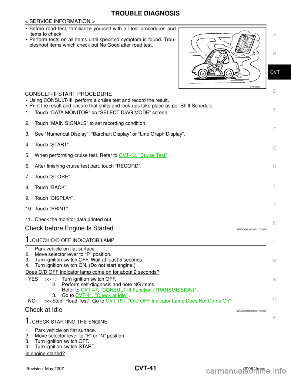
• Before road test, familiarize yourself with all test procedures and
items to check.
• Perform tests on all items until specified symptom is found. Trou-
bleshoot items which check out No Good after road test.
CONSULT-III START PROCEDURE
• Using CONSULT-III, perform a cruise test and record the result.
• Print the result and ensure that shifts and lock-ups take place as per Shift Schedule.
1. Touch “DATA MONITOR” on “SELECT DIAG MODE” screen.
2. Touch “MAIN SIGNALS” to set recording condition.
3. See “Numerical Display”, “Barchart Display” or “Line Graph Display”.
4. Touch “START”.
5. When performing cruise test. Refer to CVT-43, "
Cruise Test" .
6. After finishing cruise test part, touch “RECORD”.
7. Touch “STORE”.
8. Touch “BACK”.
9. Touch “DISPLAY”.
10. Touch “PRINT”.
11. Check the monitor data printed out.
Check before Engine Is StartedINFOID:0000000001703458
1.CHECK O/D OFF INDICATOR LAMP
1. Park vehicle on flat surface.
2. Move selector lever to “P” position.
3. Turn ignition switch OFF. Wait at least 5 seconds.
4. Turn ignition switch ON. (Do not start engine.)
Does O/D OFF indicator lamp come on for about 2 seconds?
YES >> 1. Turn ignition switch OFF.
2. Perform self-diagnosis and note NG items.
Refer to CVT-47, "
CONSULT-III Function (TRANSMISSION)" .
3. Go to CVT-41, "
Check at Idle" .
NO >> Stop “Road Test”. Go to CVT-151, "
O/D OFF Indicator Lamp Does Not Come On" .
Check at IdleINFOID:0000000001703459
1.CHECK STARTING THE ENGINE
1. Park vehicle on flat surface.
2. Move selector lever to “P” or “N” position.
3. Turn ignition switch OFF.
4. Turn ignition switch START.
Is engine started?
SAT496G
Page 899 of 2771
CVT-60
< SERVICE INFORMATION >
DTC P0615 START SIGNAL CIRCUIT
DTC P0615 START SIGNAL CIRCUIT
DescriptionINFOID:0000000001703476
• TCM controls starter relay in IPDM E/R.
• TCM switches starter relay ON at “P” or “N” position and allows to crank engine.
• Then it prohibits cranking other than at “P” or “N” position.
CONSULT-III Reference Value in Data Monitor ModeINFOID:0000000001703477
On Board Diagnosis LogicINFOID:0000000001703478
• This is not an OBD-II self-diagnostic item.
• Diagnostic trouble code “P0615 STARTER RELAY/CIRC” with CONSULT-III is detected when starter relay
switched ON other than at “P” or “N” position. (or when switched OFF at “P” or “N” position).
Possible CauseINFOID:0000000001703479
• Harness or connectors
(Starter relay and TCM circuit is open or shorted.)
• Starter relay
DTC Confirmation ProcedureINFOID:0000000001703480
CAUTION:
Always drive vehicle at a safe speed.
NOTE:
If “DTC Confirmation Procedure” has been previously performed, always turn ignition switch OFF and
wait at least 10 seconds before performing the next test.
After the repair, touch “ERASE” on “SELF-DIAG RESULTS” and then perform the following procedure to con-
firm the malfunction is eliminated.
WITH CONSULT-III
1. Turn ignition switch ON. (Do not start engine.)
2. Select “DATA MONITOR” mode for “TRANSMISSION” with CONSULT-III.
3. Start engine.
4. Drive vehicle for at least 2 consecutive seconds.
5. If DTC is detected, go to CVT-62, "
Diagnosis Procedure" .
Item name Condition Display value
STRTR RLY OUTSelector lever in “P” and “N” positions ON
Selector lever in other positions OFF
STRTR RLY MONSelector lever in “P” and “N” positions ON
Selector lever in other positions OFF
Page 901 of 2771
CVT-62
< SERVICE INFORMATION >
DTC P0615 START SIGNAL CIRCUIT
Diagnosis Procedure
INFOID:0000000001703482
1.CHECK STARTER RELAY SIGNAL
With CONSULT-III
1. Turn ignition switch ON. (Do not start engine.)
2. Select “SELECTION FROM MENU” in “DATA MONITOR” mode for “TRANSMISSION” with CONSULT-III
and check monitor “STRTR RLY OUT”, “STRTR RLY MON”(PNP relay) ON/OFF.
Without CONSULT-III
1. Turn ignition switch ON. (Do not start engine.)
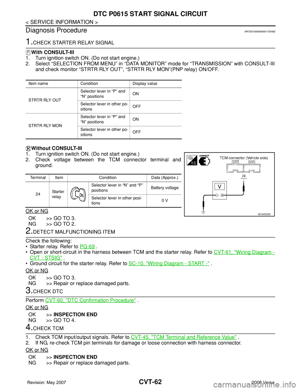
2. Check voltage between the TCM connector terminal and
ground.
OK or NG
OK >> GO TO 3.
NG >> GO TO 2.
2.DETECT MALFUNCTIONING ITEM
Check the following:
• Starter relay. Refer to PG-69
.
• Open or short-circuit in the harness between TCM and the starter relay. Refer to CVT-61, "
Wiring Diagram -
CVT - STSIG" .
• Ground circuit for the starter relay. Refer to SC-10, "
Wiring Diagram - START -" .
OK or NG
OK >> GO TO 3.
NG >> Repair or replace damaged parts.
3.CHECK DTC
Perform CVT-60, "
DTC Confirmation Procedure" .
OK or NG
OK >>INSPECTION END
NG >> GO TO 4.
4.CHECK TCM
1. Check TCM input/output signals. Refer to CVT-45, "
TCM Terminal and Reference Value" .
2. If NG, re-check TCM pin terminals for damage or loose connection with harness connector.
OK or NG
OK >>INSPECTION END
NG >> Repair or replace damaged parts.
Item name Condition Display value
STRTR RLY OUTSelector lever in “P” and
“N” positionsON
Selector lever in other po-
sitionsOFF
STRTR RLY MONSelector lever in “P” and
“N” positionsON
Selector lever in other po-
sitionsOFF
Terminal Item Condition Data (Approx.)
24Sta r te r
relaySelector lever in “N” and “P”
positionsBattery voltage
Selector lever in other posi-
tions0 V
SCIA2022E
Page 902 of 2771
DTC P0703 STOP LAMP SWITCH CIRCUIT
CVT-63
< SERVICE INFORMATION >
D
E
F
G
H
I
J
K
L
MA
B
CVT
N
O
P
DTC P0703 STOP LAMP SWITCH CIRCUIT
DescriptionINFOID:0000000001703483
ON, OFF status of the stop lamp switch is sent via the CAN communication from the combination meter to
TCM using the signal.
CONSULT-III Reference Value in Data Monitor ModeINFOID:0000000001703484
On Board Diagnosis LogicINFOID:0000000001703485
• This is not an OBD-II self-diagnostic item.
• Diagnostic trouble code “P0703 BRAKE SW/CIRC” with CONSULT-III is detected when the stop lamp switch
does not switch to ON and OFF.
- The stop lamp switch does not switch to ON, OFF.
Possible CauseINFOID:0000000001703486
• Harness or connectors
(Stop lamp switch, and combination meter circuit are open or shorted.)
(CAN communication line is open or shorted.)
• Stop lamp switch
DTC Confirmation ProcedureINFOID:0000000001703487
CAUTION:
Always drive vehicle at a safe speed.
NOTE:
If “DTC Confirmation Procedure” has been previously performed, always turn ignition switch OFF and
wait at least 10 seconds before performing the next test.
After the repair, touch “ERASE” on “SELF-DIAG RESULTS” and then perform the following procedure to con-
firm the malfunction is eliminated.
WITH CONSULT-III
1. Turn ignition switch ON. (Do not start engine.)
2. Select “DATA MONITOR” mode for “TRANSMISSION” with CONSULT-III.
3. Start engine.
4. Start vehicle for at least 3 consecutive seconds.
5. If DTC is detected, go to CVT-63, "
Diagnosis Procedure".
Diagnosis ProcedureINFOID:0000000001703488
1.CHECK CAN COMMUNICATION LINE
Perform the self-diagnosis check. Refer to CVT-47, "
CONSULT-III Function (TRANSMISSION)".
Is any malfunction of the
“U1000 CAN COMM CIRCUIT” indicated?
YES >> Check CAN communication line. Refer to CVT-56.
NO >> GO TO 2.
2.CHECK STOP LAMP SWITCH CIRCUIT
With CONSULT-III
1. Turn ignition switch ON. (Do not start engine.)
2. Select “ECU INPUT SIGNALS” in “DATA MONITOR” mode for “TRANSMISSION” with CONSULT-III.
3. Read out ON/OFF switching action of the “BRAKE SW”.
Item name Condition Display value
BRAKE SWDepressed brake pedal ON
Released brake pedal OFF
Page 904 of 2771

DTC P0705 PARK/NEUTRAL POSITION SWITCH
CVT-65
< SERVICE INFORMATION >
D
E
F
G
H
I
J
K
L
MA
B
CVT
N
O
P
DTC P0705 PARK/NEUTRAL POSITION SWITCH
DescriptionINFOID:0000000001703489
• The PNP switch is included in the control valve assembly.
• The PNP switch includes 4 transmission position switches.
• TCM judges the selector lever position by the PNP switch signal.
CONSULT-III Reference Value in Data Monitor ModeINFOID:0000000001703490
On Board Diagnosis LogicINFOID:0000000001703491
• This is an OBD-II self-diagnostic item.
• Diagnostic trouble code “P0705 PNP SW/CIRC” with CONSULT-III is detected under the following condi-
tions.
- When TCM does not receive the correct voltage signal from the PNP switches 1, 2, 3 and 4 based on the
gear position.
- When the signal from monitor terminal of PNP switch 3 is different from PNP switch 3.
Possible CauseINFOID:0000000001703492
• Harness or connectors
(PNP switches 1, 2, 3, 4 and TCM circuit is open or shorted.)
• PNP switches 1, 2, 3, 4
• PNP switch 3 monitor terminal is open or shorted
DTC Confirmation ProcedureINFOID:0000000001703493
CAUTION:
Always drive vehicle at a safe speed.
NOTE:
If “DTC Confirmation Procedure” has been previously performed, always turn ignition switch OFF and
wait at least 10 seconds before performing the next test.
After the repair, touch “ERASE” on “SELF-DIAG RESULTS” and then perform the following procedure to con-
firm the malfunction is eliminated.
WITH CONSULT-III
Shift position PNP switch 1 PNP switch 2 PNP switch 3 PNP switch 4 PNP switch 3 (monitor)
P OFF OFF OFF OFF OFF
R ON OFF OFF ON OFF
N ON ON OFF OFF OFF
DONONONON ON
L OFF ON ON OFF ON
Item name Condition Display value
INH SW3MSelector lever in “D” and “L” positions ON
Selector lever in “P”, “R” and “N” positions OFF
INH SW4Selector lever in “R” and “D” positions ON
Selector lever in “P”, “N” and “L” positions OFF
INH SW3Selector lever in “D” and “L” positions ON
Selector lever in “P”, “R” and “N” positions OFF
INH SW2Selector lever in “N”, “D” and “L” positions ON
Selector lever in “P” and “R” positions OFF
INH SW1Selector lever in “R”, “N” and “D” positions ON
Selector lever in “P” and “L” positions OFF
Page 907 of 2771
CVT-68
< SERVICE INFORMATION >
DTC P0705 PARK/NEUTRAL POSITION SWITCH
Diagnosis Procedure
INFOID:0000000001703495
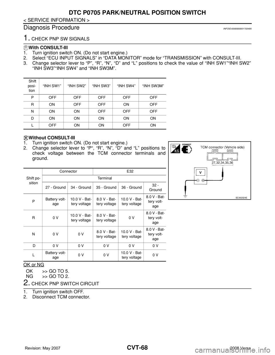
1. CHECK PNP SW SIGNALS
With CONSULT-III
1. Turn ignition switch ON. (Do not start engine.)
2. Select “ECU INPUT SIGNALS” in “DATA MONITOR” mode for “TRANSMISSION” with CONSULT-III.
3. Change selector lever to “P”, “R”, “N”, “D” and “L” positions to check the value of “INH SW1”“INH SW2”
“INH SW3”“INH SW4” and “INH SW3M”.
Without CONSULT-III
1. Turn ignition switch ON. (Do not start engine.)
2. Change selector lever to “P“, “R”, “N”, “D” and “L” positions to
check voltage between the TCM connector terminals and
ground.
OK or NG
OK >> GO TO 5.
NG >> GO TO 2.
2. CHECK PNP SWITCH CIRCUIT
1. Turn ignition switch OFF.
2. Disconnect TCM connector.
Shift
posi-
tion“INH SW1” “INH SW2” “INH SW3” “INH SW4” “INH SW3M”
P OFF OFF OFF OFF OFF
R ON OFF OFF ON OFF
N ON ON OFF OFF OFF
DON ON ON ON ON
L OFF ON ON OFF ON
Shift po-
sitionConnector E32
Te r m i n a l
27 - Ground 34 - Ground 35 - Ground 36 - Ground32 -
Ground
PBattery volt-
age10.0 V - Bat-
tery voltage8.0 V - Bat-
tery voltage10.0 V - Bat-
tery voltage8.0 V - Bat-
tery volt-
age
R0 V10.0 V - Bat-
tery voltage8.0 V - Bat-
tery voltage0 V8.0 V - Bat-
tery volt-
age
N0 V 0 V8.0 V - Bat-
tery voltage10.0 V - Bat-
tery voltage8.0 V - Bat-
tery volt-
age
D 0 V 0 V 0 V 0 V 0 V
LBattery volt-
age0 V 0 V10.0 V - Bat-
tery voltage0 V
SCIA2024E
Page 910 of 2771
DTC P0710 CVT FLUID TEMPERATURE SENSOR CIRCUIT
CVT-71
< SERVICE INFORMATION >
D
E
F
G
H
I
J
K
L
MA
B
CVT
N
O
P
DTC P0710 CVT FLUID TEMPERATURE SENSOR CIRCUIT
DescriptionINFOID:0000000001703497
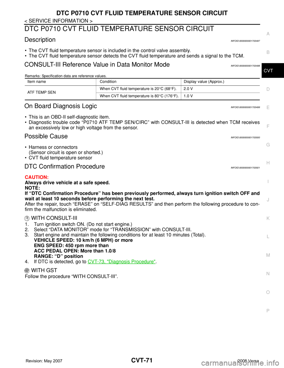
• The CVT fluid temperature sensor is included in the control valve assembly.
• The CVT fluid temperature sensor detects the CVT fluid temperature and sends a signal to the TCM.
CONSULT-III Reference Value in Data Monitor ModeINFOID:0000000001703498
Remarks: Specification data are reference values.
On Board Diagnosis LogicINFOID:0000000001703499
• This is an OBD-II self-diagnostic item.
• Diagnostic trouble code “P0710 ATF TEMP SEN/CIRC” with CONSULT-III is detected when TCM receives
an excessively low or high voltage from the sensor.
Possible CauseINFOID:0000000001703500
• Harness or connectors
(Sensor circuit is open or shorted.)
• CVT fluid temperature sensor
DTC Confirmation ProcedureINFOID:0000000001703501
CAUTION:
Always drive vehicle at a safe speed.
NOTE:
If “DTC Confirmation Procedure” has been previously performed, always turn ignition switch OFF and
wait at least 10 seconds before performing the next test.
After the repair, touch “ERASE” on “SELF-DIAG RESULTS” and then perform the following procedure to con-
firm the malfunction is eliminated.
WITH CONSULT-III
1. Turn ignition switch ON. (Do not start engine.)
2. Select “DATA MONITOR” mode for “TRANSMISSION” with CONSULT-III.
3. Start engine and maintain the following conditions for at least 10 minutes (Total).
VEHICLE SPEED: 10 km/h (6 MPH) or more
ENG SPEED: 450 rpm more than
ACC PEDAL OPEN: More than 1.0/8
RANGE: “D” position
4. If DTC is detected, go to CVT-73, "
Diagnosis Procedure".
WITH GST
Follow the procedure “WITH CONSULT-III”.
Item name Condition Display value (Approx.)
ATF TEMP SEN When CVT fluid temperature is 20°C (68°F). 2.0 V
When CVT fluid temperature is 80°C (176°F). 1.0 V
Page 912 of 2771
DTC P0710 CVT FLUID TEMPERATURE SENSOR CIRCUIT
CVT-73
< SERVICE INFORMATION >
D
E
F
G
H
I
J
K
L
MA
B
CVT
N
O
P
Diagnosis ProcedureINFOID:0000000001703503
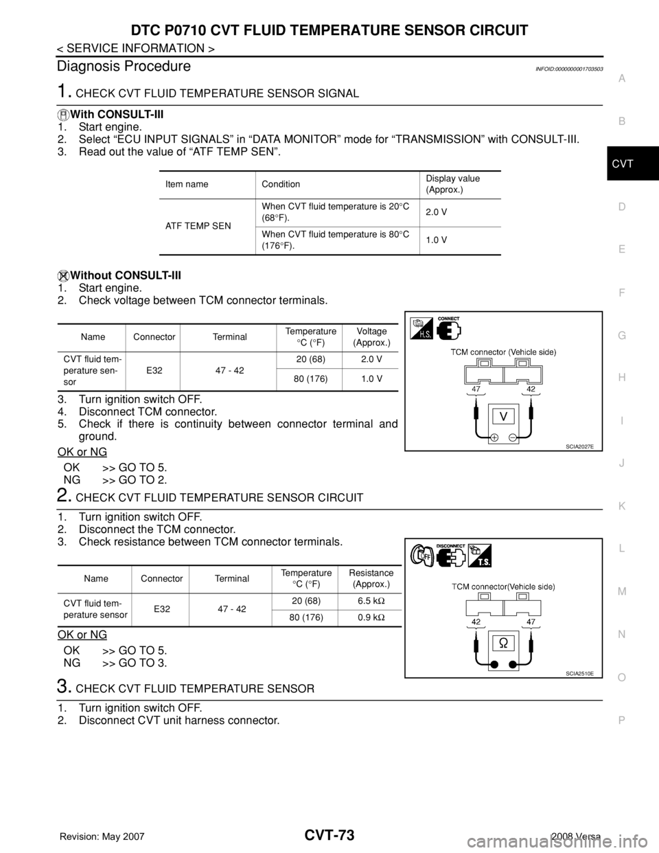
1. CHECK CVT FLUID TEMPERATURE SENSOR SIGNAL
With CONSULT-III
1. Start engine.
2. Select “ECU INPUT SIGNALS” in “DATA MONITOR” mode for “TRANSMISSION” with CONSULT-III.
3. Read out the value of “ATF TEMP SEN”.
Without CONSULT-III
1. Start engine.
2. Check voltage between TCM connector terminals.
3. Turn ignition switch OFF.
4. Disconnect TCM connector.
5. Check if there is continuity between connector terminal and
ground.
OK or NG
OK >> GO TO 5.
NG >> GO TO 2.
2. CHECK CVT FLUID TEMPERATURE SENSOR CIRCUIT
1. Turn ignition switch OFF.
2. Disconnect the TCM connector.
3. Check resistance between TCM connector terminals.
OK or NG
OK >> GO TO 5.
NG >> GO TO 3.
3. CHECK CVT FLUID TEMPERATURE SENSOR
1. Turn ignition switch OFF.
2. Disconnect CVT unit harness connector.
Item name ConditionDisplay value
(Approx.)
ATF TEMP SENWhen CVT fluid temperature is 20°C
(68°F).2.0 V
When CVT fluid temperature is 80°C
(176°F).1.0 V
Name Connector TerminalTemperature
°C (°F)Voltage
(Approx.)
CVT fluid tem-
perature sen-
sorE32 47 - 4220 (68) 2.0 V
80 (176) 1.0 V
SCIA2027E
Name Connector TerminalTemperature
°C (°F)Resistance
(Approx.)
CVT fluid tem-
perature sensorE32 47 - 4220 (68) 6.5 kΩ
80 (176) 0.9 kΩ
SCIA2510E