2008 NISSAN LATIO turn signal
[x] Cancel search: turn signalPage 501 of 2771
REMOTE KEYLESS ENTRY SYSTEM
BL-67
< SERVICE INFORMATION >
C
D
E
F
G
H
J
K
L
MA
B
BL
N
O
P
OK or NG
OK >> Key switch circuit is OK.
NG >> GO TO 2.
2.CHECK KEY SWITCH
1. Turn ignition switch OFF.
2. Disconnect key switch and key lock solenoid connector.
3. Check key switch.
OK or NG
OK >> Check the following.
• 10A fuse [No. 14, located in fuse block (J/B)]
• Harness for open or short between key switch and
fuse
• Harness for open or short between BCM and key
switch
NG >> Replace key switch and key lock solenoid.
Hazard Function CheckINFOID:0000000001703989
1.CHECK HAZARD WARNING LAMP
Does hazard warning lamp flash with hazard switch?
OK or NG
OK >> Hazard warning lamp circuit is OK.
NG >> Check hazard circuit. Refer to LT- 4 8
.
Horn Function CheckINFOID:0000000001703990
First perform the “SELF-DIAG RESULTS” in “BCM” with CONSULT-III, then perform the trouble diagnosis of
malfunction system indicated “SELF-DIAG RESULTS” of “BCM”. Refer to BCS-17, "
CAN Communication
Inspection Using CONSULT-III (Self-Diagnosis)" .
1.CHECK HORN FUNCTION
Does horn sound with horn switch?
OK or NG
OK >> GO TO 2.
NG >> Check horn circuit. Refer to WW-37
.
2.CHECK IPDM E/R INPUT SIGNAL
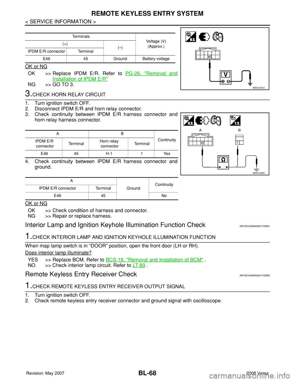
Check voltage between IPDM E/R connector and ground.
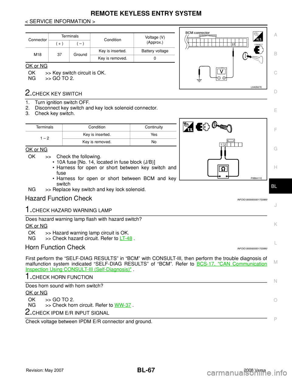
ConnectorTe r m i n a l s
ConditionVoltage (V)
(Approx.)
( + ) ( – )
M18 37 GroundKey is inserted. Battery voltage
Key is removed. 0
LIIA0567E
Terminals Condition Continuity
1 – 2Key is inserted. Yes
Key is removed. No
PIIB6411E
Page 502 of 2771
BL-68
< SERVICE INFORMATION >
REMOTE KEYLESS ENTRY SYSTEM
OK or NG
OK >> Replace IPDM E/R. Refer to PG-26, "Removal and
Installation of IPDM E/R"
NG >> GO TO 3.
3.CHECK HORN RELAY CIRCUIT
1. Turn ignition switch OFF.
2. Disconnect IPDM E/R and horn relay connector.
3. Check continuity between IPDM E/R harness connector and
horn relay harness connector.
4. Check continuity between IPDM E/R harness connector and
ground.
OK or NG
OK >> Check condition of harness and connector.
NG >> Repair or replace harness.
Interior Lamp and Ignition Keyhole Illumination Function CheckINFOID:0000000001703991
1.CHECK INTERIOR LAMP AND IGNITION KEYHOLE ILLUMINATION FUNCTION
When map lamp switch is in “DOOR” position, open the front door (LH or RH).
Does interior lamp illuminate?
YES >> Replace BCM. Refer to BCS-18, "Removal and Installation of BCM" .
NO >> Check interior lamp circuit. Refer to LT- 8 9
.
Remote Keyless Entry Receiver CheckINFOID:0000000001703992
1.CHECK REMOTE KEYLESS ENTRY RECEIVER OUTPUT SIGNAL
1. Turn ignition switch OFF.
2. Check remote keyless entry receiver connector and ground signal with oscilloscope.
Te r m i n a l s
Voltage (V)
(Approx.) (+)
(–)
IPDM E/R connector Terminal
E46 45 Ground Battery voltage
WIIA1251E
AB
Continuity
IPDM E/R
connectorTe r m i n a lHorn relay
connectorTe r m i n a l
E46 45 H-1 1 Yes
A
GroundContinuity
IPDM E/R connector Terminal
E46 45 No
WIIA1252E
Page 514 of 2771
BL-80
< SERVICE INFORMATION >
INTELLIGENT KEY SYSTEM
BCM sends headlamp request signal and horn signal to IPDM E/R. Then, IPDM E/R turns on and off head-
lamp and horn intermittently.
The headlamp flashes and the horn sounds intermittently.
The alarm automatically turns off:
• After 25 seconds
• When Intelligent Key unit receives any signal from remote controller of Intelligent Key
• When door request switch is pressed (Intelligent Key is outside vehicle)
Panic alarm function's press and holding time value can be changed in “PANIC ALARM DELAY” mode in
“WORK SUPPORT”. Refer to BL-101, "
CONSULT-III Application Item".
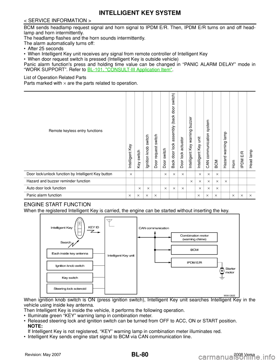
List of Operation Related Parts
Parts marked with × are the parts related to operation.
ENGINE START FUNCTION
When the registered Intelligent Key is carried, the engine can be started without inserting the key.
When ignition knob switch is ON (press ignition switch), Intelligent Key unit searches Intelligent Key in the
vehicle using inside key antenna.
Then Intelligent Key is inside the vehicle, it performs the following operation.
• Illuminate green “KEY” warning lamp in combination meter.
• Released steering lock and ignition switch can be turned from OFF to ACC, ON or START position.
NOTE:
If Intelligent Key is not registered, “KEY” warning lamp in combination meter illuminates red.
• Intelligent Key sends engine start signal to BCM via CAN communication line.
Remote keyless entry functions
Intelligent Key
Key switch
Ignition knob switch
Door request switch
Door switch
Back door lock assembly (back door switch)
Door lock actuator
Intelligent Key warning buzzer
Intelligent Key unit
CAN communication system
BCM
Hazard warning lamp
Horn
IPDM E/R
Head lamp
Door lock/unlock function by Intelligent Key button×××××××
Hazard and buzzer reminder function×××××
Auto door lock function×× ××× ×××
Panic alarm function×××× ××× ×××
WIIA1282E
Page 515 of 2771

INTELLIGENT KEY SYSTEM
BL-81
< SERVICE INFORMATION >
C
D
E
F
G
H
J
K
L
MA
B
BL
N
O
P
When ignition switch turns to START position, BCM sends starter request signal to IPDM E/R. Then, engine
starts.
Even if Intelligent Key battery runs down, Intelligent key unit can start engine with mechanical key built Intelli-
gent Key. For details, refer toBL-210
.
All of the originally supplied Intelligent Key IDs (except for key) have been registered in Intelligent Key system.
If requested by the vehicle owner, a maximum of four Intelligent Key IDs can be registered into the Intelligent
Key system components.
List of Operation Related Parts
Parts marked with × are the parts related to operation.
WARNING CHIME/BUZZER/LAMPS FUNCTION
Operation Description
The following warning chime (combination meter), Intelligent Key warning buzzer (front door LH), Intelligent
Key warning buzzer (trunk)
*, warning lamps "KEY" and “P-SHIFT” (with CVT) or "LOCK" (with M/T) are given
to the user as warning information while using the intelligent key system.
• Ignition switch warning chime
• Ignition key warning chime
• OFF position warning chime
• Take away warning chime
• Door lock operation warning chime
• Intelligent key low battery warning
• P position warning (with CVT)
• LOCK position warning (with M/T)
NOTE:
For key-in-ignition warning chime related concerns only, refer to DI-41
.
* :
Sedan
Operation Condition
Engine start functions
Intelligent Key
Key switch
Ignition knob switch
Inside key antenna
Intelligent Key unit
CAN communication system
BCM
Combination meter
IPDM E/R
NATS antenna amp.
Steering lock solenoid
Engine start function by the Intelligent Key××××××××× ×
Engine start function by the mechanical key× ××× ×××
Operation ConditionWarning chime/buzzer Warning lamp
Chime
(combina-
tion meter)Buzzer(s) KEYLOCK
(M/T)P-SHIFT
(CVT)
Ignition switch warning chime• Mechanical key is out of ignition switch
(Key switch is OFF)
• Ignition switch is in the ACC, OFF or
LOCK position.
[ignition switch is pressed
(ignition knob switch is ON).]
• Driver door is open.activate — — — —
Ignition key warning chime
(When mechanical key is used)• Mechanical key is inserted in ignition
switch (key switch is ON).
• Ignition switch is in the ACC, OFF or
LOCK position.
• Driver door is open.activate — — — —
Page 517 of 2771

INTELLIGENT KEY SYSTEM
BL-83
< SERVICE INFORMATION >
C
D
E
F
G
H
J
K
L
MA
B
BL
N
O
P
CHANGE SETTINGS FUNCTION
The settings for each function can be changed with the CONSULT-III.
Changing Settings Using CONSULT-III
The settings for the Intelligent Key system functions can be changed using CONSULT-III (WORK SUPPORT).
Refer to BL-101, "
CONSULT-III Application Item".
NOTE:
Once a function setting is changed, it will remain effective even if the battery is disconnected.
INTELLIGENT KEY REGISTRATION
Intelligent Key-ID registration is performed using the CONSULT-III.
CAUTION:
• After a new Intelligent Key-ID is registered, be sure to check the function.
• When registering an additional Intelligent Key-ID, take any Intelligent Keys already registered and
Intelligent Keys for any other vehicles out of the vehicle before starting.
CONSULT-III can be used to check and delete Intelligent Key-IDs.
For further information, see the CONSULT-III Operation Manual NATS.
STEERING LOCK SOLENOID REGISTRATION
Steering Lock Solenoid ID Registration
CAUTION:
• The method for registering a steering lock solenoid ID depends on the status of the steering lock
solenoid and Intelligent Key unit (new or old unit).
• After registration is completed, press ignition switch with an Intelligent Key in the vehicle so that it
can be turned, and confirm that it cannot be turned even when ignition switch is pressed without an
Intelligent Key in the vehicle.
For further information, see the CONSULT-III Operation Manual NATS-IVIS/NVIS.
CAN Communication System DescriptionINFOID:0000000001704000
Refer to LAN-6.
Warning and alarm functions
Intelligent Key
Key switch
Ignition knob switch
Ignition switch ACC position input signal
Ignition switch ON position input signal
Door switch
Door request switch
Inside key antenna
Outside key antenna (Driver, Passenger)
Outside key antenna (rear bumper)
Intelligent Key warning buzzer(s)
Intelligent Key unit
CAN communication system
BCM
Warning lamp
Warning chime (combination meter)
Ignition switch warning chime× ×× ××× ×
Ignition key warning chime
(When mechanical key used)××× ×××
OFF position warning chimeFor internal××× ××××××
For external×××× ×××××
Take away warning chimeRight after door is
closed××× × × ×××××
Any door is open××× × × ××××
Take away from
window××× × × ××××××
Door lock operation warning chime× ××××××××
Intelligent Key low battery warning××××××
Page 544 of 2771
BL-110
< SERVICE INFORMATION >
INTELLIGENT KEY SYSTEM
With CONSULT-III
• Connect CONSULT-III, and turn ignition switch ON.
• Touch “INTELLIGENT KEY” on “SELECT SYSTEM” screen.
• Touch “SELF-DIAG RESULTS” on “SELECT DIAG MODE” screen.
• Check display content in self-diagnostic results.
OK or NG
NO DTC IS DETECTED>> INSPECTION END
CAN COMM [U1000]>> After printing “SELF-DIAGNOSIS RESULTS”, go to “CAN SYSTEM”. Refer to LAN-
15, "Trouble Diagnosis Flow Chart".
CAN COMM2 [U1010]>> Replace Intelligent Key unit.
Power Supply and Ground Circuit InspectionINFOID:0000000001704014
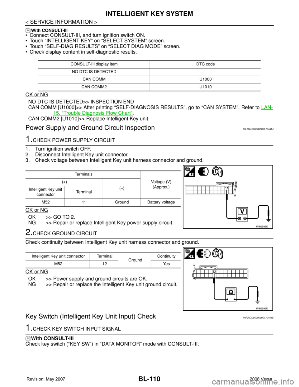
1.CHECK POWER SUPPLY CIRCUIT
1. Turn ignition switch OFF.
2. Disconnect Intelligent Key unit connector.
3. Check voltage between Intelligent Key unit harness connector and ground.
OK or NG
OK >> GO TO 2.
NG >> Repair or replace Intelligent Key power supply circuit.
2.CHECK GROUND CIRCUIT
Check continuity between Intelligent Key unit harness connector and ground.
OK or NG
OK >> Power supply and ground circuits are OK.
NG >> Repair or replace the Intelligent Key unit ground circuit.
Key Switch (Intelligent Key Unit Input) CheckINFOID:0000000001704015
1.CHECK KEY SWITCH INPUT SIGNAL
With CONSULT-III
Check key switch (“KEY SW”) in “DATA MONITOR” mode with CONSULT-III.
CONSULT-III display item DTC code
NO DTC IS DETECTED —
CAN COMM U1000
CAN COMM2 U1010
Te r m i n a l s
Voltage (V)
(Approx.) (+)
(–)
Intelligent Key unit
connectorTe r m i n a l
M52 11 Ground Battery voltage
PIIB6595E
Intelligent Key unit connector Terminal
GroundContinuity
M52 12 Yes
PIIB6596E
Page 547 of 2771
INTELLIGENT KEY SYSTEM
BL-113
< SERVICE INFORMATION >
C
D
E
F
G
H
J
K
L
MA
B
BL
N
O
P
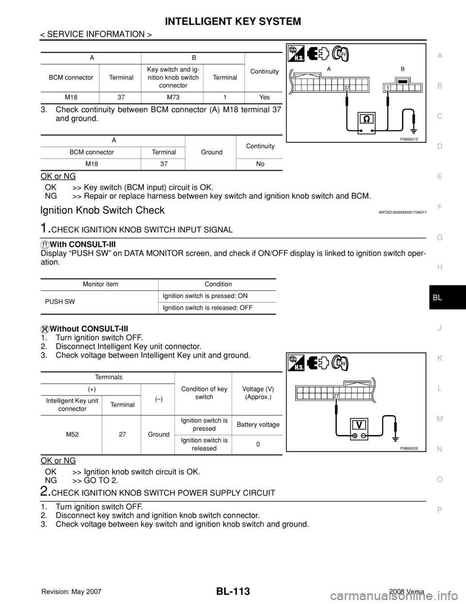
3. Check continuity between BCM connector (A) M18 terminal 37
and ground.
OK or NG
OK >> Key switch (BCM input) circuit is OK.
NG >> Repair or replace harness between key switch and ignition knob switch and BCM.
Ignition Knob Switch CheckINFOID:0000000001704017
1.CHECK IGNITION KNOB SWITCH INPUT SIGNAL
With CONSULT-III
Display “PUSH SW” on DATA MONITOR screen, and check if ON/OFF display is linked to ignition switch oper-
ation.
Without CONSULT-III
1. Turn ignition switch OFF.
2. Disconnect Intelligent Key unit connector.
3. Check voltage between Intelligent Key unit and ground.
OK or NG
OK >> Ignition knob switch circuit is OK.
NG >> GO TO 2.
2.CHECK IGNITION KNOB SWITCH POWER SUPPLY CIRCUIT
1. Turn ignition switch OFF.
2. Disconnect key switch and ignition knob switch connector.
3. Check voltage between key switch and ignition knob switch and ground.
AB
Continuity
BCM connector TerminalKey switch and ig-
nition knob switch
connectorTe r m i n a l
M18 37 M73 1 Yes
A
GroundContinuity
BCM connector Terminal
M18 37 No
PIIB6601E
Monitor item Condition
PUSH SWIgnition switch is pressed: ON
Ignition switch is released: OFF
Te r m i n a l s
Condition of key
switchVoltage (V)
(Approx.) (+)
(–)
Intelligent Key unit
connectorTe r m i n a l
M52 27 GroundIgnition switch is
pressedBattery voltage
Ignition switch is
released0
PIIB6602E
Page 554 of 2771
BL-120
< SERVICE INFORMATION >
INTELLIGENT KEY SYSTEM
OK or NG
OK >> GO TO 4.
NG >> Replace front door request switch.
4.CHECK DOOR REQUEST SWITCH GROUND CIRCUIT
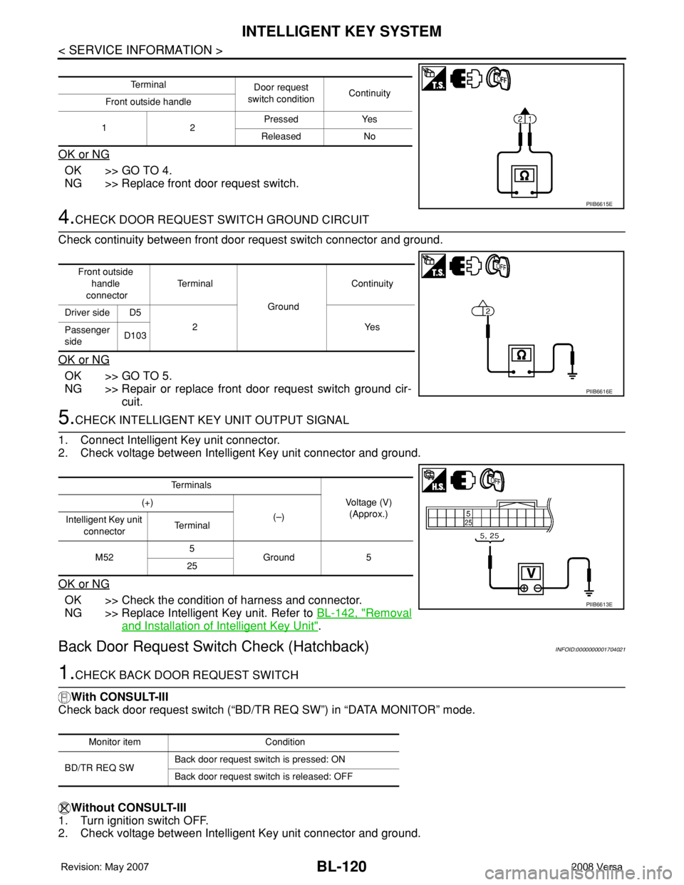
Check continuity between front door request switch connector and ground.
OK or NG
OK >> GO TO 5.
NG >> Repair or replace front door request switch ground cir-
cuit.
5.CHECK INTELLIGENT KEY UNIT OUTPUT SIGNAL
1. Connect Intelligent Key unit connector.
2. Check voltage between Intelligent Key unit connector and ground.
OK or NG
OK >> Check the condition of harness and connector.
NG >> Replace Intelligent Key unit. Refer to BL-142, "
Removal
and Installation of Intelligent Key Unit".
Back Door Request Switch Check (Hatchback)INFOID:0000000001704021
1.CHECK BACK DOOR REQUEST SWITCH
With CONSULT-III
Check back door request switch (“BD/TR REQ SW”) in “DATA MONITOR” mode.
Without CONSULT-III
1. Turn ignition switch OFF.
2. Check voltage between Intelligent Key unit connector and ground.
Te r m i n a l
Door request
switch conditionContinuity
Front outside handle
12Pressed Yes
Released No
PIIB6615E
Front outside
handle
connectorTe r m i n a l
GroundContinuity
Driver side D5
2Yes
Passenger
sideD103
PIIB6616E
Te r m i n a l s
Voltage (V)
(Approx.) (+)
(–)
Intelligent Key unit
connectorTe r m i n a l
M525
Ground 5
25
PIIB6613E
Monitor item Condition
BD/TR REQ SWBack door request switch is pressed: ON
Back door request switch is released: OFF