Page 385 of 2771
AV-26
< SERVICE INFORMATION >
AUDIO
Satellite Radio Tuner (Factory Installed) Left Channel Audio Signal Circuit Inspection
INFOID:0000000001704666
1.CHECK HARNESS
1. Turn ignition switch OFF.
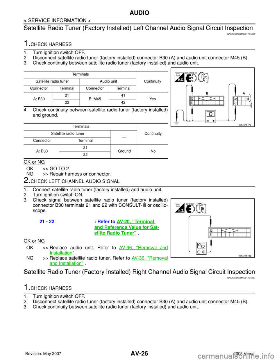
2. Disconnect satellite radio tuner (factory installed) connector B30 (A) and audio unit connector M45 (B).
3. Check continuity between satellite radio tuner (factory installed) and audio unit.
4. Check continuity between satellite radio tuner (factory installed)
and ground.
OK or NG
OK >> GO TO 2.
NG >> Repair harness or connector.
2.CHECK LEFT CHANNEL AUDIO SIGNAL
1. Connect satellite radio tuner (factory installed) and audio unit.
2. Turn ignition switch ON.
3. Check signal between satellite radio tuner (factory installed)
connector B30 terminals 21 and 22 with CONSULT-Ill or oscillo-
scope.
OK or NG
OK >> Replace audio unit. Refer to AV-36, "Removal and
Installation" .
NG >> Replace satellite radio tuner. Refer to AV-36, "
Removal
and Installation" .
Satellite Radio Tuner (Factory Installed) Right Channel Audio Signal Circuit Inspection
INFOID:0000000001704667
1.CHECK HARNESS
1. Turn ignition switch OFF.
2. Disconnect satellite radio tuner (factory installed) connector B30 (A) and audio unit connector M45 (B).
3. Check continuity between satellite radio tuner (factory installed) and audio unit.
Te r m i n a l s
Continuity Satellite radio tuner Audio unit
Connector Terminal Connector Terminal
A: B3021
B: M4541
Ye s
22 42
Te r m i n a l s
Continuity Satellite radio tuner
—
Connector Terminal
A: B3021
Ground No
22
WKIA4547E
21 - 22 : Refer to AV-20, "Terminal
and Reference Value for Sat-
ellite Radio Tuner" .
WKIA4548E
Page 386 of 2771

AUDIO
AV-27
< SERVICE INFORMATION >
C
D
E
F
G
H
I
J
L
MA
B
AV
N
O
P
4. Check continuity between satellite radio tuner (factory installed)
and ground.
OK or NG
OK >> GO TO 2.
NG >> Repair harness or connector.
2.CHECK RIGHT CHANNEL AUDIO SIGNAL
1. Connect satellite radio tuner (factory installed) and audio unit.
2. Turn ignition switch ON.
3. Check signal between satellite radio tuner (factory installed)
connector B30 terminals 23 and 24 with CONSULT-lIl or oscillo-
scope.
OK or NG
OK >> Replace audio unit. Refer to AV-36, "Removal and
Installation" .
NG >> Replace satellite radio tuner. Refer to AV-36, "
Removal
and Installation" .
Steering Switch Check (With Bluetooth)INFOID:0000000001704668
1.CHECK HARNESS
1. Turn ignition switch OFF.
2. Disconnect Bluetooth control unit connector and spiral cable connector M30.
3. Check continuity between Bluetooth control unit (A) connector B121 terminals 12, 14, and 13 and spiral
cable (B) connector M30 terminals 24, 31, and 32.
4. Check continuity between Bluetooth control unit and ground.
Te r m i n a l s
Continuity Satellite radio tuner Audio unit
Connector Terminal Connector Terminal
A: B3023
B: M4543
Ye s
24 44
Te r m i n a l s
Continuity Satellite radio tuner
—
Connector Terminal
A: B3023
Ground No
24
WKIA4549E
23 - 24 : Refer to AV-20, "Terminal
and Reference Value for Sat-
ellite Radio Tuner" .
WKIA4550E
Te r m i n a l s
Continuity AB
Connector Terminal Connector Terminal
B12112
M3024
Ye s 13 32
14 31
WKIA5348E
Page 388 of 2771
AUDIO
AV-29
< SERVICE INFORMATION >
C
D
E
F
G
H
I
J
L
MA
B
AV
N
O
P
OK >> Inspection End.
NG >> Replace steering switch. Refer to AV-36, "
Removal and Installation" .
Sound Is Not Heard from Front Door Speaker (Base System)INFOID:0000000001704669
1.HARNESS CHECK
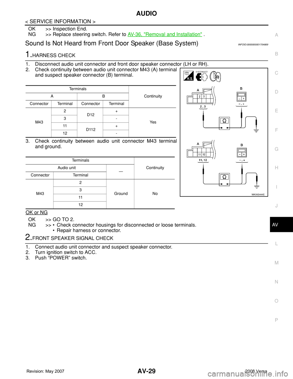
1. Disconnect audio unit connector and front door speaker connector (LH or RH).
2. Check continuity between audio unit connector M43 (A) terminal
and suspect speaker connector (B) terminal.
3. Check continuity between audio unit connector M43 terminal
and ground.
OK or NG
OK >> GO TO 2.
NG >> • Check connector housings for disconnected or loose terminals.
• Repair harness or connector.
2.FRONT SPEAKER SIGNAL CHECK
1. Connect audio unit connector and suspect speaker connector.
2. Turn ignition switch to ACC.
3. Push “POWER” switch.
Te r m i n a l s
Continuity A B
Connector Terminal Connector Terminal
M432
D12+
Ye s 3-
11
D112+
12 -
Te r m i n a l s
Continuity Audio unit
—
Connector Terminal
M432
Ground No 3
11
12
WKIA5444E
Page 390 of 2771
AUDIO
AV-31
< SERVICE INFORMATION >
C
D
E
F
G
H
I
J
L
MA
B
AV
N
O
P
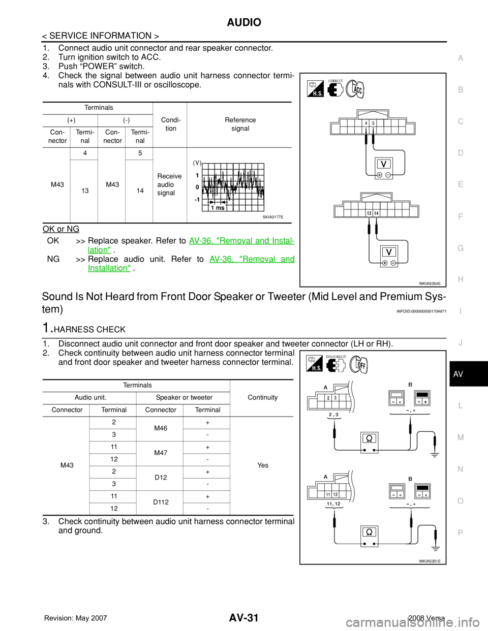
1. Connect audio unit connector and rear speaker connector.
2. Turn ignition switch to ACC.
3. Push “POWER” switch.
4. Check the signal between audio unit harness connector termi-
nals with CONSULT-III or oscilloscope.
OK or NG
OK >> Replace speaker. Refer to AV-36, "Removal and Instal-
lation" .
NG >> Replace audio unit. Refer to AV-36, "
Removal and
Installation" .
Sound Is Not Heard from Front Door Speaker or Tweeter (Mid Level and Premium Sys-
tem)
INFOID:0000000001704671
1.HARNESS CHECK
1. Disconnect audio unit connector and front door speaker and tweeter connector (LH or RH).
2. Check continuity between audio unit harness connector terminal
and front door speaker and tweeter harness connector terminal.
3. Check continuity between audio unit harness connector terminal
and ground.
Te r m i n a l s
Condi-
tionReference
signal (+) (-)
Con-
nectorTe r m i -
nalCon-
nectorTe r m i -
nal
M434
M435
Receive
audio
signal 13 14
WKIA5354E
SKIA0177E
Te r m i n a l s
Continuity Audio unit. Speaker or tweeter
Connector Terminal Connector Terminal
M432
M46+
Ye s 3-
11
M47+
12 -
2
D12+
3-
11
D112+
12 -
WKIA5351E
Page 391 of 2771
AV-32
< SERVICE INFORMATION >
AUDIO
OK or NG
OK >> GO TO 2.
NG >> • Check connector housings for disconnected or loose terminals.
• Repair harness or connector.
2.FRONT SPEAKER SIGNAL CHECK
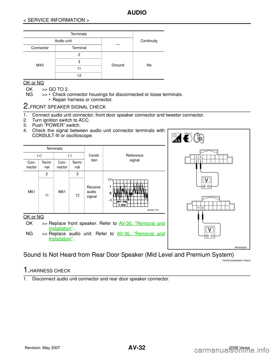
1. Connect audio unit connector, front door speaker connector and tweeter connector.
2. Turn ignition switch to ACC.
3. Push “POWER” switch.
4. Check the signal between audio unit connector terminals with
CONSULT-III or oscilloscope.
OK or NG
OK >> Replace front speaker. Refer to AV-36, "Removal and
Installation" .
NG >> Replace audio unit. Refer to AV-36, "
Removal and
Installation" .
Sound Is Not Heard from Rear Door Speaker (Mid Level and Premium System)
INFOID:0000000001704672
1.HARNESS CHECK
1. Disconnect audio unit connector and rear door speaker connector.
Te r m i n a l s
Continuity Audio unit
—
Connector Terminal
M432
Ground No 3
11
12
Te r m i n a l s
Condi-
tionReference
signal (+) (-)
Con-
nectorTe r m i -
nalCon-
nectorTe r m i -
nal
M512
M513
Receive
audio
signal 11 1 2
WKIA5352E
SKIA0177E
Page 392 of 2771
AUDIO
AV-33
< SERVICE INFORMATION >
C
D
E
F
G
H
I
J
L
MA
B
AV
N
O
P
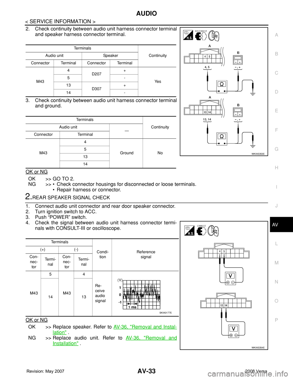
2. Check continuity between audio unit harness connector terminal
and speaker harness connector terminal.
3. Check continuity between audio unit harness connector terminal
and ground.
OK or NG
OK >> GO TO 2.
NG >> • Check connector housings for disconnected or loose terminals.
• Repair harness or connector.
2.REAR SPEAKER SIGNAL CHECK
1. Connect audio unit connector and rear door speaker connector.
2. Turn ignition switch to ACC.
3. Push “POWER” switch.
4. Check the signal between audio unit harness connector termi-
nals with CONSULT-III or oscilloscope.
OK or NG
OK >> Replace speaker. Refer to AV-36, "Removal and Instal-
lation" .
NG >> Replace audio unit. Refer to AV-36, "
Removal and
Installation" .
Te r m i n a l s
Continuity Audio unit Speaker
Connector Terminal Connector Terminal
M434
D207+
Ye s 5-
13
D307+
14 -
Te r m i n a l s
Continuity Audio unit
—
Connector Terminal
M434
Ground No 5
13
14
WKIA5353E
Te r m i n a l s
Condi-
tionReference
signal (+) (-)
Con-
nec-
torTe r m i -
nalCon-
nec-
torTe r m i -
nal
M435
M434
Re-
ceive
audio
signal 14 13
WKIA5354E
SKIA0177E
Page 393 of 2771
AV-34
< SERVICE INFORMATION >
AUDIO
Sound Is Not Heard from Subwoofer (Premium System)
INFOID:0000000001704673
1.CHECK FUSE
Check that the following fuse is not blown.
OK or NG
OK >> GO TO 2.
NG >> If fuse is blown, be sure to eliminate cause of blown fuse before installing new fuse. Refer to PG-
3 .
2.EQ SETTING CHECK
1. Ensure that subwoofer amp. connector B29 and audio unit harness connectors M43, M44 and M45 are
securely connected.
2. Turn the ignition switch to the ACC position.
3. Press the "AUDIO", "AUX", and "TUNE DOWN" switches simultaneously, the current EQ Setting will be
displayed.
Is "Woofer On" displayed?
YES >> GO TO 3.
NO >> Disconnect all audio unit harness connectors and wait for 2 minutes in order to reset the audio
unit. Reconnect audio unit connectors M44 and M45 first followed by M43 last. Repeat Steps 1
through 3 to confirm that "Woofer On" is now displayed.
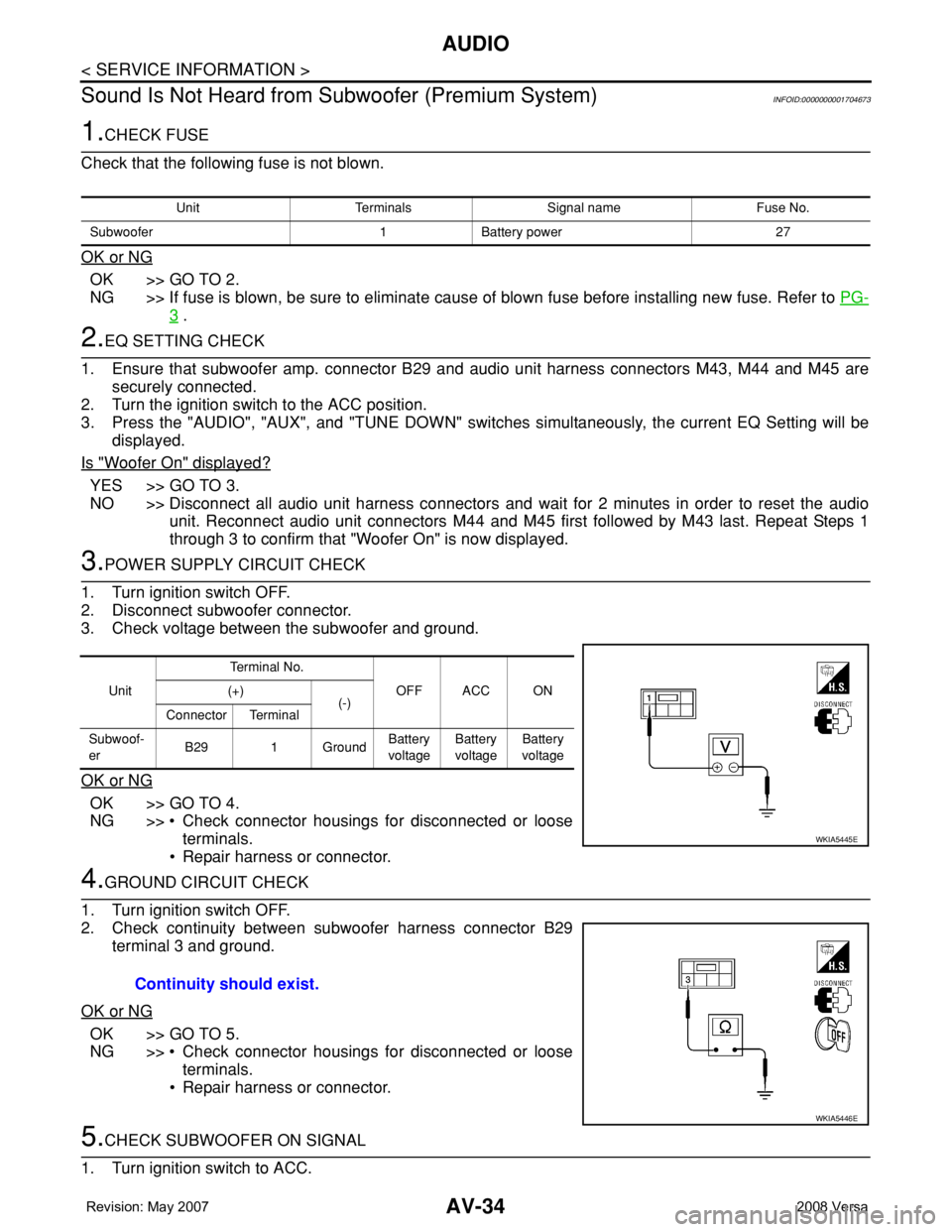
3.POWER SUPPLY CIRCUIT CHECK
1. Turn ignition switch OFF.
2. Disconnect subwoofer connector.
3. Check voltage between the subwoofer and ground.
OK or NG
OK >> GO TO 4.
NG >> • Check connector housings for disconnected or loose
terminals.
• Repair harness or connector.
4.GROUND CIRCUIT CHECK
1. Turn ignition switch OFF.
2. Check continuity between subwoofer harness connector B29
terminal 3 and ground.
OK or NG
OK >> GO TO 5.
NG >> • Check connector housings for disconnected or loose
terminals.
• Repair harness or connector.
5.CHECK SUBWOOFER ON SIGNAL
1. Turn ignition switch to ACC.
Unit Terminals Signal name Fuse No.
Subwoofer 1 Battery power 27
UnitTe r m i n a l N o .
OFF ACC ON (+)
(-)
Connector Terminal
Subwoof-
erB29 1 GroundBattery
voltageBattery
voltageBattery
voltage
WKIA5445E
Continuity should exist.
WKIA5446E
Page 394 of 2771
AUDIO
AV-35
< SERVICE INFORMATION >
C
D
E
F
G
H
I
J
L
MA
B
AV
N
O
P
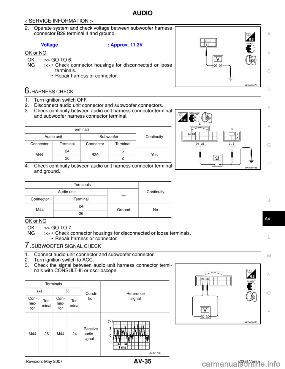
2. Operate system and check voltage between subwoofer harness
connector B29 terminal 4 and ground.
OK or NG
OK >> GO TO 6.
NG >> • Check connector housings for disconnected or loose
terminals.
• Repair harness or connector.
6.HARNESS CHECK
1. Turn ignition switch OFF.
2. Disconnect audio unit connector and subwoofer connectors.
3. Check continuity between audio unit harness connector terminal
and subwoofer harness connector terminal.
4. Check continuity between audio unit harness connector terminal
and ground.
OK or NG
OK >> GO TO 7.
NG >> • Check connector housings for disconnected or loose terminals.
• Repair harness or connector.
7.SUBWOOFER SIGNAL CHECK
1. Connect audio unit connector and subwoofer connector.
2. Turn ignition switch to ACC.
3. Check the signal between audio unit harness connector termi-
nals with CONSULT-III or oscilloscope.Voltage : Approx. 11.3V
WKIA5447E
Te r m i n a l s
Continuity Audio unit Subwoofer
Connector Terminal Connector Terminal
M4424
B296
Ye s
26 2
Te r m i n a l s
Continuity Audio unit
—
Connector Terminal
M4424
Ground No
26
WKIA5448E
Te r m i n a l s
Condi-
tionReference
signal (+) (-)
Con-
nec-
torTe r -
minalCon-
nec-
torTe r -
minal
M4426M4424Receive
audio
signal
WKIA5449E
SKIA0177E