Page 448 of 2771
BL-14
< SERVICE INFORMATION >
HOOD
5. After adjustment tighten lock bolts to the specified torque.
6. Install the front grille. Refer to EI-20
.
Removal and InstallationINFOID:0000000001703948
HOOD ASSEMBLY
Removal
1. Remove hinge nuts on hood and remove hood assembly.
CAUTION:
Two technicians should be used to avoid damaging the
hood during removal.
1. Hood striker 2. Primary latch 3. Secondary striker
4. Secondary latch
A : 20 mm (0.79 in)
B : 6.8 mm (0.268 in) min.
PIIB5794E
1. Hood hinge 2. Hood stay 3. Radiator core seal rubber
4. Hood assembly 5. Hood insulator 6. Hood stay holder
PIIB2528J
12.7 N·m (1.3 kg-m, 9.4 ft-lb)
PIIB2529J
Page 662 of 2771

BL-228
< SERVICE INFORMATION >
BODY REPAIR
4. Front pillar inner reinforcement (RH&LH)
5. Lower dash reinforcement
6. 4th crossmember (RH&LH)
7. Front side member rear extension (RH&LH)
8. 3rd crossmember (RH&LH)
9. Front seat outer rear bracket (RH&LH)
10. Front seat inner rear bracket (RH&LH)
11. 2nd crossmember (RH&LH)
12. Front seat outer front bracket (RH&LH)
13. Front seat inner front bracket (RH&LH)
14. Fender bracket (RH&LH)
15. Strut housing assembly RH
16. Cowl top side upper (RH&LH)
17. Front strut housing (RH&LH)
18. Upper torque rod reinforcement
19. Closing plate assembly RH
20. Engine mount reinforcement
21. Strut tower front reinforcement RH
22. Front hoodledge lower RH
23. Frame bracket outer (RH&LH)
24. Front bumper support bracket (RH&LH)
25. Closing plate (RH&LH)
26. Front suspension rear bracket (RH&LH)
27. Front side member outrigger (RH&LH)
28. Front side member assembly (RH&LH)
29. Front side member (RH&LH)
30. Frame bracket (RH&LH)
31. Closing plate assembly LH
32. Hoodledge connector (RH&LH)
33. Radiator core side support (RH&LH)
34. Radiator core support upper (RH&LH)
35. Hoodledge upper (RH&LH)
36. Hoodledge reinforcement assembly (RH&LH)
37. Dash side (RH&LH)
38. Dash side assembly (RH& LH)
39. Front floor reinforcement (RH&LH)
40. Front floor front (RH&LH)
41. Front floor center
42. Rear seat crossmember
43. Rear center crossmember
44. Rear seat upper crossmember
45. Rear side member (RH&LH)
46. Sill inner extension (RH&LH)
47. Rear side member extension (RH&LH)
48. Rear side member assembly (RH & LH)
49. Rear floor front
50. Rear floor front assembly
51. Rear floor side (RH&LH)
52. Rear floor rear
Page 701 of 2771

BODY REPAIR
BL-267
< SERVICE INFORMATION >
C
D
E
F
G
H
J
K
L
MA
B
BL
N
O
P
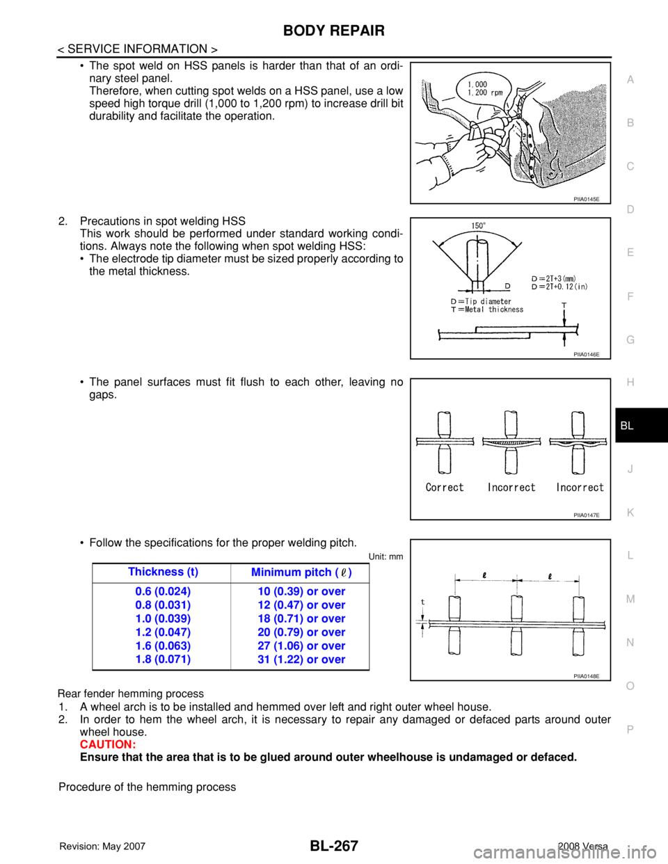
• The spot weld on HSS panels is harder than that of an ordi-
nary steel panel.
Therefore, when cutting spot welds on a HSS panel, use a low
speed high torque drill (1,000 to 1,200 rpm) to increase drill bit
durability and facilitate the operation.
2. Precautions in spot welding HSS
This work should be performed under standard working condi-
tions. Always note the following when spot welding HSS:
• The electrode tip diameter must be sized properly according to
the metal thickness.
• The panel surfaces must fit flush to each other, leaving no
gaps.
• Follow the specifications for the proper welding pitch.
Unit: mm
Rear fender hemming process
1. A wheel arch is to be installed and hemmed over left and right outer wheel house.
2. In order to hem the wheel arch, it is necessary to repair any damaged or defaced parts around outer
wheel house.
CAUTION:
Ensure that the area that is to be glued around outer wheelhouse is undamaged or defaced.
Procedure of the hemming process
PIIA0145E
PIIA0146E
PIIA0147E
Thickness (t)
Minimum pitch ( )
0.6 (0.024)
0.8 (0.031)
1.0 (0.039)
1.2 (0.047)
1.6 (0.063)
1.8 (0.071)10 (0.39) or over
12 (0.47) or over
18 (0.71) or over
20 (0.79) or over
27 (1.06) or over
31 (1.22) or over
PIIA0148E
Page 733 of 2771

BR-2
< SERVICE INFORMATION >
PRECAUTIONS
SERVICE INFORMATION
PRECAUTIONS
Precaution for Supplemental Restraint System (SRS) "AIR BAG" and "SEAT BELT
PRE-TENSIONER"
INFOID:0000000001703775
The Supplemental Restraint System such as “AIR BAG” and “SEAT BELT PRE-TENSIONER”, used along
with a front seat belt, helps to reduce the risk or severity of injury to the driver and front passenger for certain
types of collision. This system includes seat belt switch inputs and dual stage front air bag modules. The SRS
system uses the seat belt switches to determine the front air bag deployment, and may only deploy one front
air bag, depending on the severity of a collision and whether the front occupants are belted or unbelted.
Information necessary to service the system safely is included in the SRS and SB section of this Service Man-
ual.
WARNING:
• To avoid rendering the SRS inoperative, which could increase the risk of personal injury or death in
the event of a collision which would result in air bag inflation, all maintenance must be performed by
an authorized NISSAN/INFINITI dealer.
• Improper maintenance, including incorrect removal and installation of the SRS, can lead to personal
injury caused by unintentional activation of the system. For removal of Spiral Cable and Air Bag
Module, see the SRS section.
• Do not use electrical test equipment on any circuit related to the SRS unless instructed to in this
Service Manual. SRS wiring harnesses can be identified by yellow and/or orange harnesses or har-
ness connectors.
Precaution for Brake SystemINFOID:0000000001703776
• Refill using recommended brake fluid. Refer to MA-10.
• Never reuse drained brake fluid.
• Be careful not to splash brake fluid on painted surface of body. If brake fluid is splashed on painted surfaces
of body immediately wipe it off with cloth and then wash it away with water.
• To clean or wash all parts of master cylinder, disc brake caliper and wheel cylinder, use new brake fluid.
• Never use mineral oils such as gasoline or kerosene. They will ruin rubber parts of the hydraulic system.
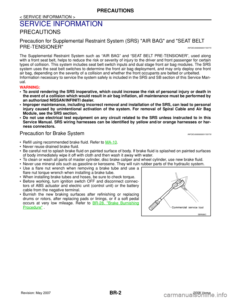
• Use a flare nut wrench when removing a brake tube and use a
flare nut torque wrench when installing a brake tube.
• When installing brake tubes and hoses, be sure to check torque.
• Before working, turn ignition switch OFF and disconnect connec-
tors of ABS actuator and electric unit (control unit) or the battery
cable from the negative terminal.
• Burnish the new braking surfaces after refinishing or replacing
drums or rotors, after replacing pads or linings, or if a soft pedal
occurs at very low mileage. Refer toBR-28, "
Brake Burnishing
Procedure" .
SBR686C
Page 734 of 2771
PREPARATION
BR-3
< SERVICE INFORMATION >
C
D
E
G
H
I
J
K
L
MA
B
BR
N
O
P
PREPARATION
Commercial Service ToolINFOID:0000000001703777
Tool nameDescription
1. Flare nut crowfoot
2. Torque wrenchRemoving and installing brake piping
a: 10 mm (0.39 in)/12 mm (0.47 in)
Pin punch
Tip diameter: 4 mm (0.16 in) dia. Removing and installing reservoir tank pin
S-NT360
ZZA0515D
Page 740 of 2771
BRAKE FLUID
BR-9
< SERVICE INFORMATION >
C
D
E
G
H
I
J
K
L
MA
B
BR
N
O
P
3. With brake pedal depressed, loosen bleed valve to let the air out, and then tighten it immediately.
4. Repeat steps 2, 3 until no more air comes out.
5. Tighten bleed valve to specified torque. Refer to BR-23, "
Component" (front disc brake), BR-29, "Compo-
nent" (rear drum brake).
6. Following the steps 1 to 5 above, with master cylinder reservoir tank filled at least half way, bleed air from
the rear right, front left, rear left, and front right brake, in that order.
Page 742 of 2771

BRAKE TUBE AND HOSE
BR-11
< SERVICE INFORMATION >
C
D
E
G
H
I
J
K
L
MA
B
BR
N
O
P
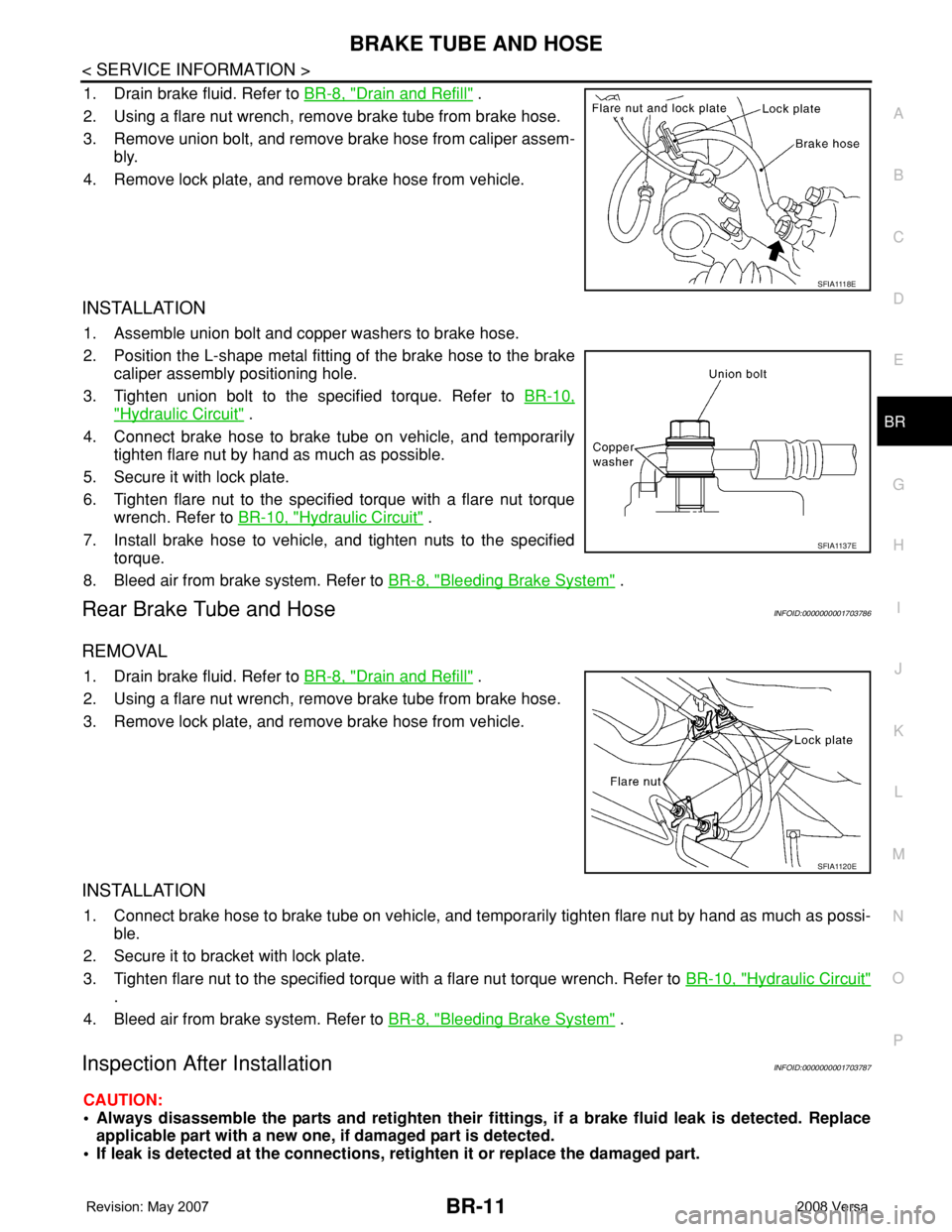
1. Drain brake fluid. Refer to BR-8, "Drain and Refill" .
2. Using a flare nut wrench, remove brake tube from brake hose.
3. Remove union bolt, and remove brake hose from caliper assem-
bly.
4. Remove lock plate, and remove brake hose from vehicle.
INSTALLATION
1. Assemble union bolt and copper washers to brake hose.
2. Position the L-shape metal fitting of the brake hose to the brake
caliper assembly positioning hole.
3. Tighten union bolt to the specified torque. Refer to BR-10,
"Hydraulic Circuit" .
4. Connect brake hose to brake tube on vehicle, and temporarily
tighten flare nut by hand as much as possible.
5. Secure it with lock plate.
6. Tighten flare nut to the specified torque with a flare nut torque
wrench. Refer to BR-10, "
Hydraulic Circuit" .
7. Install brake hose to vehicle, and tighten nuts to the specified
torque.
8. Bleed air from brake system. Refer to BR-8, "
Bleeding Brake System" .
Rear Brake Tube and HoseINFOID:0000000001703786
REMOVAL
1. Drain brake fluid. Refer to BR-8, "Drain and Refill" .
2. Using a flare nut wrench, remove brake tube from brake hose.
3. Remove lock plate, and remove brake hose from vehicle.
INSTALLATION
1. Connect brake hose to brake tube on vehicle, and temporarily tighten flare nut by hand as much as possi-
ble.
2. Secure it to bracket with lock plate.
3. Tighten flare nut to the specified torque with a flare nut torque wrench. Refer to BR-10, "
Hydraulic Circuit"
.
4. Bleed air from brake system. Refer to BR-8, "
Bleeding Brake System" .
Inspection After InstallationINFOID:0000000001703787
CAUTION:
• Always disassemble the parts and retighten their fittings, if a brake fluid leak is detected. Replace
applicable part with a new one, if damaged part is detected.
• If leak is detected at the connections, retighten it or replace the damaged part.
S F I A 111 8 E
SFIA1137E
SFIA1120E
Page 744 of 2771

BRAKE MASTER CYLINDER
BR-13
< SERVICE INFORMATION >
C
D
E
G
H
I
J
K
L
MA
B
BR
N
O
P
BRAKE MASTER CYLINDER
On-Board InspectionINFOID:0000000001703788
LEAK INSPECTION
• Check for leaking in a master cylinder installation surface, a reservoir tank installation surface, and brake
tube connections.
Removal and InstallationINFOID:0000000001703789
CAUTION:
Be careful not to splash brake fluid on painted areas; it may cause paint damage. If brake fluid is
splashed on painted areas, immediately wipe them with cloth and wash it away with water.
REMOVAL
1. Drain brake fluid. Refer to BR-8, "Drain and Refill" .
2. Remove battery. Refer to SC-6, "
Removal and Installation" .
3. Remove air duct. Refer to EM-16, "
Removal and Installation" .
4. Remove air cleaner. Refer to EM-16, "
Removal and Installation" .
5. Disconnect brake fluid level switch harness connector.
6. Using a flare nut wrench, remove brake tube from master cylinder.
7. Remove master cylinder assembly nuts, and remove master cylinder assembly from vehicle..
INSTALLATION
CAUTION:
• Refill using recommended brake fluid. Refer to MA-10
.
• Never reuse drained brake fluid.
• Check if the rod of primary piston has dust or scratches.
1. Install master cylinder to brake booster assembly, and tighten nuts to the specified torque. Refer to BR-18,
"Removal and Installation".
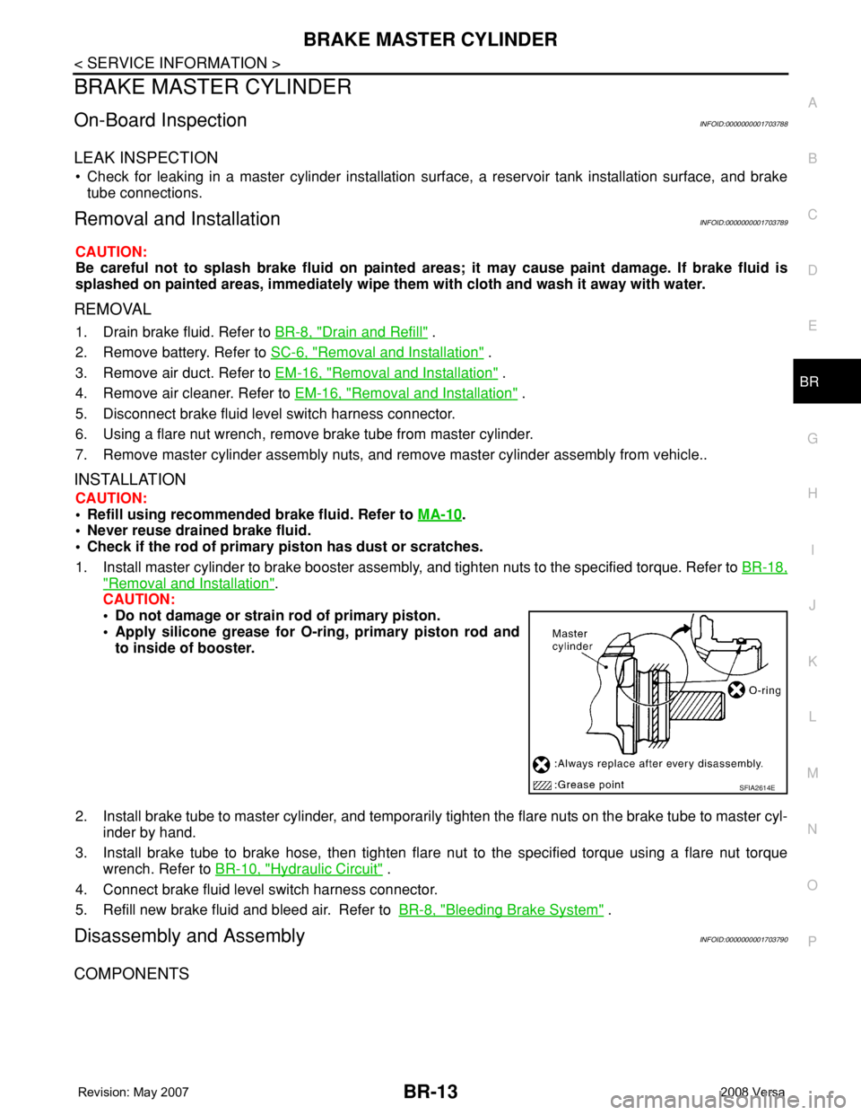
CAUTION:
• Do not damage or strain rod of primary piston.
• Apply silicone grease for O-ring, primary piston rod and
to inside of booster.
2. Install brake tube to master cylinder, and temporarily tighten the flare nuts on the brake tube to master cyl-
inder by hand.
3. Install brake tube to brake hose, then tighten flare nut to the specified torque using a flare nut torque
wrench. Refer to BR-10, "
Hydraulic Circuit" .
4. Connect brake fluid level switch harness connector.
5. Refill new brake fluid and bleed air. Refer toBR-8, "
Bleeding Brake System" .
Disassembly and AssemblyINFOID:0000000001703790
COMPONENTS
SFIA2614E