Page 892 of 2771
TROUBLE DIAGNOSIS
CVT-53
< SERVICE INFORMATION >
D
E
F
G
H
I
J
K
L
MA
B
CVT
N
O
P
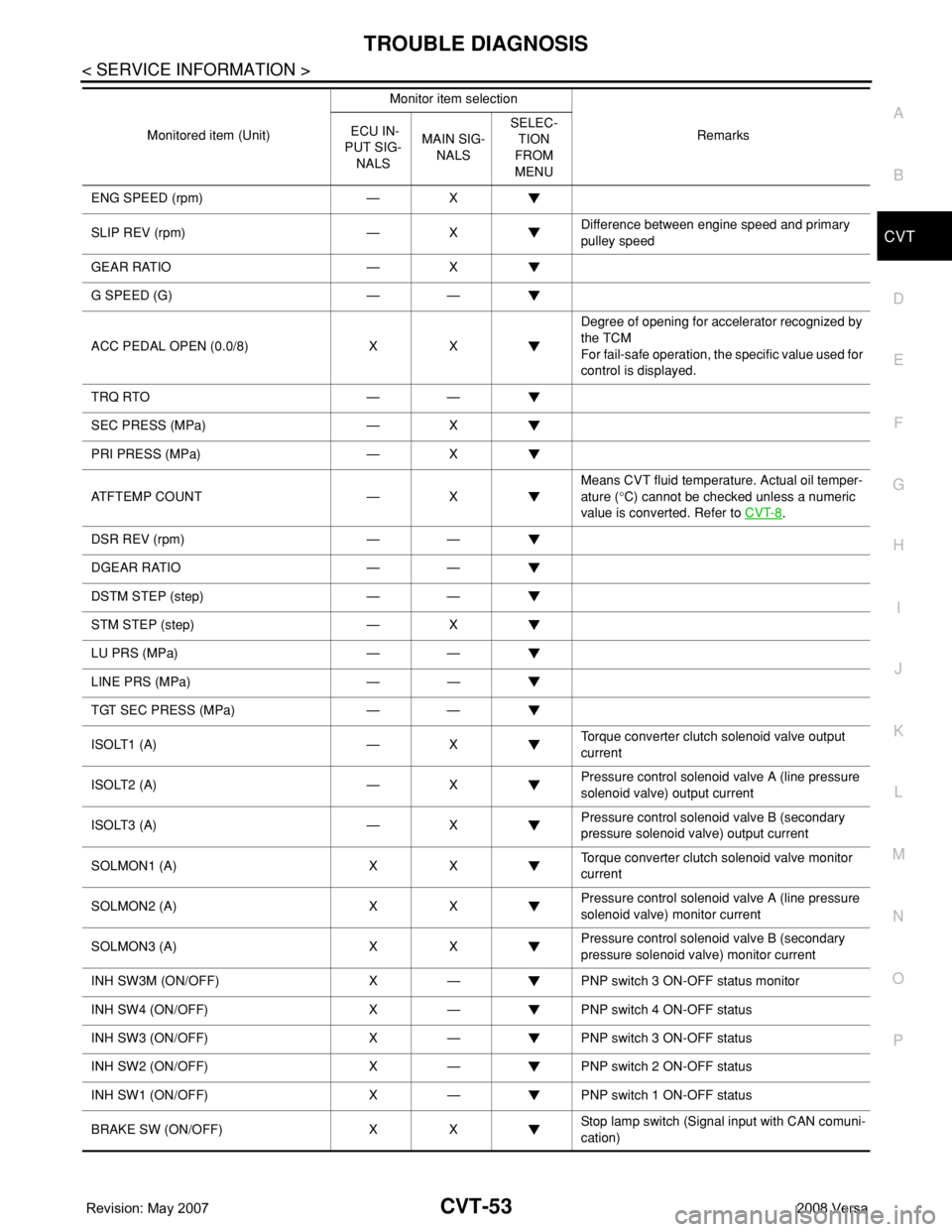
ENG SPEED (rpm) — X
SLIP REV (rpm) — XDifference between engine speed and primary
pulley speed
GEAR RATIO — X
G SPEED (G) — —
ACC PEDAL OPEN (0.0/8) X XDegree of opening for accelerator recognized by
the TCM
For fail-safe operation, the specific value used for
control is displayed.
TRQ RTO — —
SEC PRESS (MPa) — X
PRI PRESS (MPa) — X
ATFTEMP COUNT — XMeans CVT fluid temperature. Actual oil temper-
ature (°C) cannot be checked unless a numeric
value is converted. Refer to CVT-8
.
DSR REV (rpm) — —
DGEAR RATIO — —
DSTM STEP (step) — —
STM STEP (step) — X
LU PRS (MPa) — —
LINE PRS (MPa) — —
TGT SEC PRESS (MPa) — —
ISOLT1 (A) — XTorque converter clutch solenoid valve output
current
ISOLT2 (A) — XPressure control solenoid valve A (line pressure
solenoid valve) output current
ISOLT3 (A) — XPressure control solenoid valve B (secondary
pressure solenoid valve) output current
SOLMON1 (A) X XTorque converter clutch solenoid valve monitor
current
SOLMON2 (A) X XPressure control solenoid valve A (line pressure
solenoid valve) monitor current
SOLMON3 (A) X XPressure control solenoid valve B (secondary
pressure solenoid valve) monitor current
INH SW3M (ON/OFF) X — PNP switch 3 ON-OFF status monitor
INH SW4 (ON/OFF) X — PNP switch 4 ON-OFF status
INH SW3 (ON/OFF) X — PNP switch 3 ON-OFF status
INH SW2 (ON/OFF) X — PNP switch 2 ON-OFF status
INH SW1 (ON/OFF) X — PNP switch 1 ON-OFF status
BRAKE SW (ON/OFF) X XStop lamp switch (Signal input with CAN comuni-
cation) Monitored item (Unit)Monitor item selection
Remarks ECU IN-
PUT SIG-
NALSMAIN SIG-
NALSSELEC-
TION
FROM
MENU
Page 927 of 2771

CVT-88
< SERVICE INFORMATION >
DTC P0740 TORQUE CONVERTER CLUTCH SOLENOID VALVE
DTC P0740 TORQUE CONVERTER CLUTCH SOLENOID VALVE
DescriptionINFOID:0000000001703531
• The torque converter clutch solenoid valve is included in the control valve assembly.
• The torque converter clutch solenoid valve is activated by the TCM in response to signals sent from the vehi-
cle speed and accelerator pedal position sensors. Lock-up piston operation will then be controlled.
• Lock-up operation, however, is prohibited when CVT fluid temperature is too low.
• When the accelerator pedal is depressed (less than 2.0/8) in lock-up condition, the engine speed should not
change abruptly. If there is a big jump in engine speed, there is no lock-up.
CONSULT-III Reference Value in Data Monitor ModeINFOID:0000000001703532
Remarks: Specification data are reference values.
On Board Diagnosis LogicINFOID:0000000001703533
• This is an OBD-II self-diagnostic item.
• Diagnostic trouble code “P0740 TCC SOLENOID/CIRC” with CONSULT-III is detected under the following
conditions.
- TCM detects an improper voltage drop when it tries to operate the solenoid valve.
Possible CauseINFOID:0000000001703534
• Torque converter clutch solenoid valve
• Harness or connectors
(Solenoid circuit is open or shorted.)
DTC Confirmation ProcedureINFOID:0000000001703535
NOTE:
If “DTC Confirmation Procedure” has been previously performed, always turn ignition switch OFF and
wait at least 10 seconds before performing the next test.
After the repair, touch “ERASE” on “SELF-DIAG RESULTS” and then perform the following procedure to con-
firm the malfunction is eliminated.
WITH CONSULT-III
1. Turn ignition switch ON. (Do not start engine.)
2. Select “DATA MONITOR” mode for “TRANSMISSION” with CONSULT-III and wait at least 10 consecutive
seconds.
3. If DTC is detected, go to CVT-90, "
Diagnosis Procedure" .
WITH GST
Follow the procedure “WITH CONSULT-III”.
Item name Condition Display value (Approx.)
ISOLT1Lock-up OFF 0.0 A
Lock-up ON 0.7 A
Page 928 of 2771
DTC P0740 TORQUE CONVERTER CLUTCH SOLENOID VALVE
CVT-89
< SERVICE INFORMATION >
D
E
F
G
H
I
J
K
L
MA
B
CVT
N
O
P
Wiring Diagram - CVT - TCVINFOID:0000000001703536
TCM TERMINALS AND REFERENCE VALUES
Refer to CVT-45, "TCM Terminal and Reference Value" .
BCWA0674E
Page 929 of 2771
CVT-90
< SERVICE INFORMATION >
DTC P0740 TORQUE CONVERTER CLUTCH SOLENOID VALVE
Diagnosis Procedure
INFOID:0000000001703537
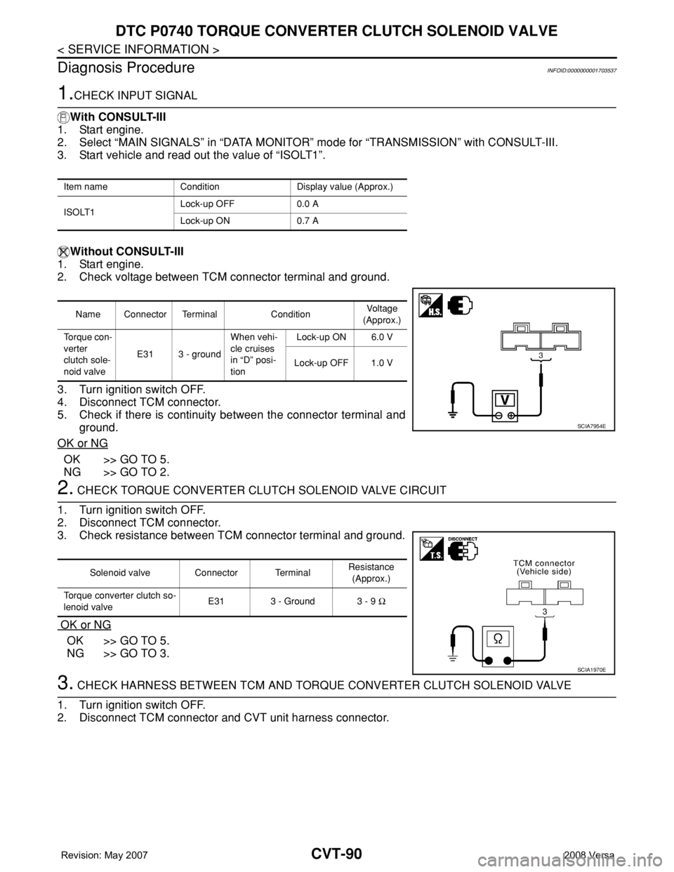
1.CHECK INPUT SIGNAL
With CONSULT-III
1. Start engine.
2. Select “MAIN SIGNALS” in “DATA MONITOR” mode for “TRANSMISSION” with CONSULT-III.
3. Start vehicle and read out the value of “ISOLT1”.
Without CONSULT-III
1. Start engine.
2. Check voltage between TCM connector terminal and ground.
3. Turn ignition switch OFF.
4. Disconnect TCM connector.
5. Check if there is continuity between the connector terminal and
ground.
OK or NG
OK >> GO TO 5.
NG >> GO TO 2.
2. CHECK TORQUE CONVERTER CLUTCH SOLENOID VALVE CIRCUIT
1. Turn ignition switch OFF.
2. Disconnect TCM connector.
3. Check resistance between TCM connector terminal and ground.
OK or NG
OK >> GO TO 5.
NG >> GO TO 3.
3. CHECK HARNESS BETWEEN TCM AND TORQUE CONVERTER CLUTCH SOLENOID VALVE
1. Turn ignition switch OFF.
2. Disconnect TCM connector and CVT unit harness connector.
Item name Condition Display value (Approx.)
ISOLT1Lock-up OFF 0.0 A
Lock-up ON 0.7 A
Name Connector Terminal ConditionVoltage
(Approx.)
To r q u e c o n -
verter
clutch sole-
noid valveE31 3 - groundWhen vehi-
cle cruises
in “D” posi-
tionLock-up ON 6.0 V
Lock-up OFF 1.0 V
SCIA7954E
Solenoid valve Connector TerminalResistance
(Approx.)
Torque converter clutch so-
lenoid valveE31 3 - Ground 3 - 9 Ω
SCIA1970E
Page 930 of 2771
DTC P0740 TORQUE CONVERTER CLUTCH SOLENOID VALVE
CVT-91
< SERVICE INFORMATION >
D
E
F
G
H
I
J
K
L
MA
B
CVT
N
O
P
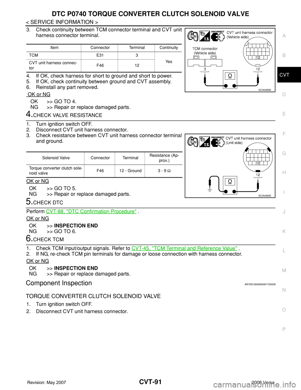
3. Check continuity between TCM connector terminal and CVT unit
harness connector terminal.
4. If OK, check harness for short to ground and short to power.
5. If OK, check continuity between ground and CVT assembly.
6. Reinstall any part removed.
OK or NG
OK >> GO TO 4.
NG >> Repair or replace damaged parts.
4.CHECK VALVE RESISTANCE
1. Turn ignition switch OFF.
2. Disconnect CVT unit harness connector.
3. Check resistance between CVT unit harness connector terminal
and ground.
OK or NG
OK >> GO TO 5.
NG >> Repair or replace damaged parts.
5.CHECK DTC
Perform CVT-88, "
DTC Confirmation Procedure" .
OK or NG
OK >>INSPECTION END
NG >> GO TO 6.
6.CHECK TCM
1. Check TCM input/output signals. Refer to CVT-45, "
TCM Terminal and Reference Value" .
2. If NG, re-check TCM pin terminals for damage or loose connection with harness connector.
OK or NG
OK >>INSPECTION END
NG >> Repair or replace damaged parts.
Component InspectionINFOID:0000000001703538
TORQUE CONVERTER CLUTCH SOLENOID VALVE
1. Turn ignition switch OFF.
2. Disconnect CVT unit harness connector.
Item Connector Terminal Continuity
TCM E31 3
Ye s
CVT unit harness connec-
torF46 12
SCIA4683E
Solenoid Valve Connector TerminalResistance (Ap-
prox.)
Torque converter clutch sole-
noid valveF46 12 - Ground 3 - 9 Ω
SCIA4684E
Page 931 of 2771
CVT-92
< SERVICE INFORMATION >
DTC P0740 TORQUE CONVERTER CLUTCH SOLENOID VALVE
3. Check resistance between CVT unit harness connector terminal
and ground.
4. If NG, replace the transaxle assembly. Refer to CVT-178,
"Removal and Installation" .
Solenoid Valve Connector TerminalResistance (Ap-
prox.)
Torque converter clutch sole-
noid valveF46 12 - Ground 3 - 9 Ω
SCIA4684E
Page 932 of 2771
DTC P0744 A/T TCC S/V FUNCTION (LOCK-UP)
CVT-93
< SERVICE INFORMATION >
D
E
F
G
H
I
J
K
L
MA
B
CVT
N
O
P
DTC P0744 A/T TCC S/V FUNCTION (LOCK-UP)
DescriptionINFOID:0000000001703539
• The torque converter clutch solenoid valve is included in the control valve assembly.
• This malfunction is detected when the torque converter clutch does not lock-up as instructed by the TCM.
This is not only caused by electrical malfunction (circuits open or shorted), but also by mechanical malfunc-
tion such as control valve sticking, improper solenoid valve operation, etc.
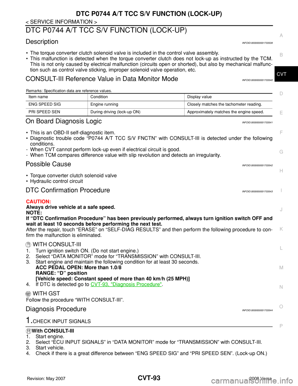
CONSULT-III Reference Value in Data Monitor ModeINFOID:0000000001703540
Remarks: Specification data are reference values.
On Board Diagnosis LogicINFOID:0000000001703541
• This is an OBD-II self-diagnostic item.
• Diagnostic trouble code “P0744 A/T TCC S/V FNCTN” with CONSULT-III is detected under the following
conditions.
- When CVT cannot perform lock-up even if electrical circuit is good.
- When TCM compares difference value with slip revolution and detects an irregularity.
Possible CauseINFOID:0000000001703542
• Torque converter clutch solenoid valve
• Hydraulic control circuit
DTC Confirmation ProcedureINFOID:0000000001703543
CAUTION:
Always drive vehicle at a safe speed.
NOTE:
If “DTC Confirmation Procedure” has been previously performed, always turn ignition switch OFF and
wait at least 10 seconds before performing the next test.
After the repair, touch “ERASE” on “SELF-DIAG RESULTS” and then perform the following procedure to con-
firm the malfunction is eliminated.
WITH CONSULT-III
1. Turn ignition switch ON. (Do not start engine.)
2. Select “DATA MONITOR” mode for “TRANSMISSION” with CONSULT-III.
3. Start engine and maintain the following condition for at least 30 seconds.
ACC PEDAL OPEN: More than 1.0/8
RANGE: “D” position
[Vehicle speed: Constant speed of more than 40 km/h (25 MPH)]
4. If DTC is detected go to CVT-93, "
Diagnosis Procedure".
WITH GST
Follow the procedure “WITH CONSULT-III”.
Diagnosis ProcedureINFOID:0000000001703544
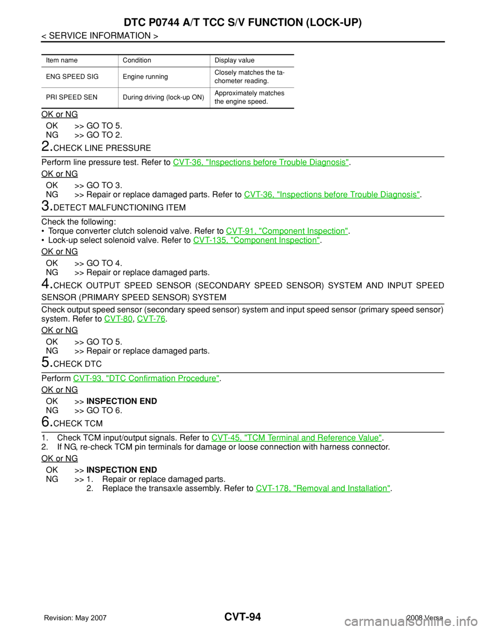
1.CHECK INPUT SIGNALS
With CONSULT-III
1. Start engine.
2. Select “ECU INPUT SIGNALS” in “DATA MONITOR” mode for “TRANSMISSION” with CONSULT-III.
3. Start vehicle.
4. Check if there is a great difference between “ENG SPEED SIG” and “PRI SPEED SEN”. (Lock-up ON.)
Item name Condition Display value
ENG SPEED SIG Engine running Closely matches the tachometer reading.
PRI SPEED SEN During driving (lock-up ON) Approximately matches the engine speed.
Page 933 of 2771
CVT-94
< SERVICE INFORMATION >
DTC P0744 A/T TCC S/V FUNCTION (LOCK-UP)
OK or NG
OK >> GO TO 5.
NG >> GO TO 2.
2.CHECK LINE PRESSURE
Perform line pressure test. Refer to CVT-36, "
Inspections before Trouble Diagnosis".
OK or NG
OK >> GO TO 3.
NG >> Repair or replace damaged parts. Refer to CVT-36, "
Inspections before Trouble Diagnosis".
3.DETECT MALFUNCTIONING ITEM
Check the following:
• Torque converter clutch solenoid valve. Refer to CVT-91, "
Component Inspection".
• Lock-up select solenoid valve. Refer to CVT-135, "
Component Inspection".
OK or NG
OK >> GO TO 4.
NG >> Repair or replace damaged parts.
4.CHECK OUTPUT SPEED SENSOR (SECONDARY SPEED SENSOR) SYSTEM AND INPUT SPEED
SENSOR (PRIMARY SPEED SENSOR) SYSTEM
Check output speed sensor (secondary speed sensor) system and input speed sensor (primary speed sensor)
system. Refer to CVT-80
, CVT-76.
OK or NG
OK >> GO TO 5.
NG >> Repair or replace damaged parts.
5.CHECK DTC
Perform CVT-93, "
DTC Confirmation Procedure".
OK or NG
OK >>INSPECTION END
NG >> GO TO 6.
6.CHECK TCM
1. Check TCM input/output signals. Refer to CVT-45, "
TCM Terminal and Reference Value".
2. If NG, re-check TCM pin terminals for damage or loose connection with harness connector.
OK or NG
OK >>INSPECTION END
NG >> 1. Repair or replace damaged parts.
2. Replace the transaxle assembly. Refer to CVT-178, "
Removal and Installation".
Item name Condition Display value
ENG SPEED SIG Engine runningClosely matches the ta-
chometer reading.
PRI SPEED SEN During driving (lock-up ON)Approximately matches
the engine speed.