Page 1799 of 2771
PREPARATION
FAX-3
< SERVICE INFORMATION >
C
E
F
G
H
I
J
K
L
MA
B
FA X
N
O
P
PREPARATION
Special Service ToolINFOID:0000000001703698
The actual shapes of Kent-Moore tools may differ from those of special service tools illustrated here.
Commercial Service ToolINFOID:0000000001703699
Tool number
(Kent-Moore No.)
Tool nameDescription
KV40107300
(—)
Boot Band crimping toolInstalling boot bands
KV38105500
(J-33904)
Differential side oil seal protectorInstalling drive shaft LH
a: 40 mm (1.57 in) dia.
KV38106700
(J-34296)
Differential side oil seal protectorInstalling drive shaft RH
a: 36 mm (1.42 in) dia.
HT72520000
(J-25730-A)
Ball joint removerRemoving tie-rod outer end and lower ball
joint
ZZA1229D
ZZA0835D
ZZA0835D
NT146
Tool nameDescription
Power tool• Removing wheel nuts
• Removing torque member bolts
• Removing hub lock nut
PBIC0190E
Page 1802 of 2771
FAX-6
< SERVICE INFORMATION >
FRONT WHEEL HUB AND KNUCKLE
2. Without disassembling the hydraulic lines, remove the torque member bolts using power tool. Then repo-
sition the torque member and brake caliper assembly aside with wire. Refer to BR-23
.
CAUTION:
Do not depress brake pedal while brake caliper is removed.
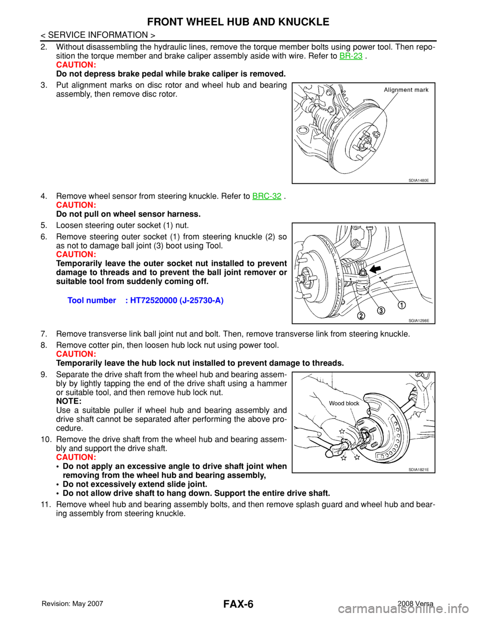
3. Put alignment marks on disc rotor and wheel hub and bearing
assembly, then remove disc rotor.
4. Remove wheel sensor from steering knuckle. Refer to BRC-32
.
CAUTION:
Do not pull on wheel sensor harness.
5. Loosen steering outer socket (1) nut.
6. Remove steering outer socket (1) from steering knuckle (2) so
as not to damage ball joint (3) boot using Tool.
CAUTION:
Temporarily leave the outer socket nut installed to prevent
damage to threads and to prevent the ball joint remover or
suitable tool from suddenly coming off.
7. Remove transverse link ball joint nut and bolt. Then, remove transverse link from steering knuckle.
8. Remove cotter pin, then loosen hub lock nut using power tool.
CAUTION:
Temporarily leave the hub lock nut installed to prevent damage to threads.
9. Separate the drive shaft from the wheel hub and bearing assem-
bly by lightly tapping the end of the drive shaft using a hammer
or suitable tool, and then remove hub lock nut.
NOTE:
Use a suitable puller if wheel hub and bearing assembly and
drive shaft cannot be separated after performing the above pro-
cedure.
10. Remove the drive shaft from the wheel hub and bearing assem-
bly and support the drive shaft.
CAUTION:
• Do not apply an excessive angle to drive shaft joint when
removing from the wheel hub and bearing assembly,
• Do not excessively extend slide joint.
• Do not allow drive shaft to hang down. Support the entire drive shaft.
11. Remove wheel hub and bearing assembly bolts, and then remove splash guard and wheel hub and bear-
ing assembly from steering knuckle.
SDIA1480E
Tool number : HT72520000 (J-25730-A)
SGIA1298E
SDIA1821E
Page 1803 of 2771
FRONT WHEEL HUB AND KNUCKLE
FAX-7
< SERVICE INFORMATION >
C
E
F
G
H
I
J
K
L
MA
B
FA X
N
O
P
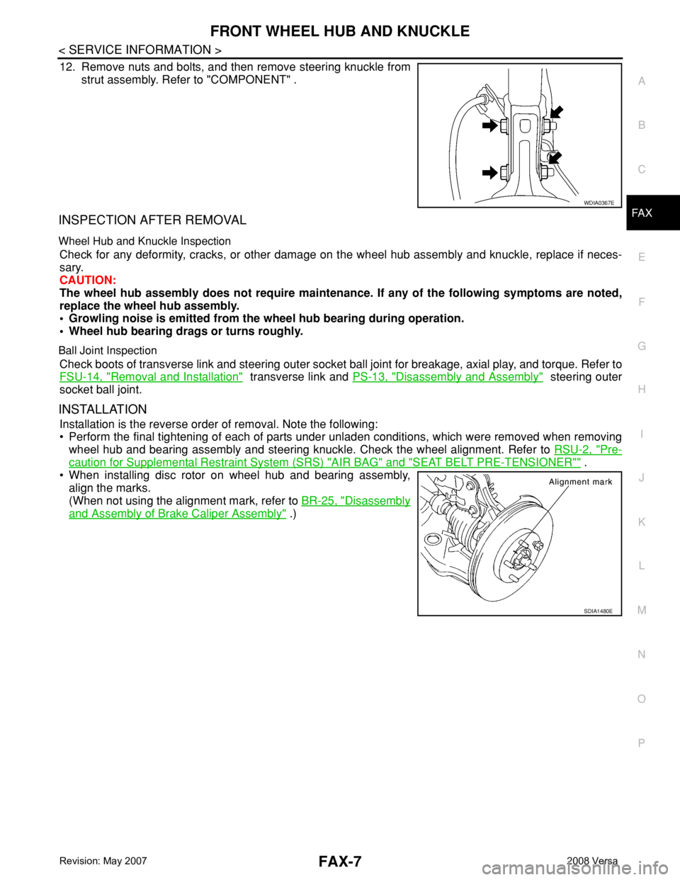
12. Remove nuts and bolts, and then remove steering knuckle from
strut assembly. Refer to "COMPONENT" .
INSPECTION AFTER REMOVAL
Wheel Hub and Knuckle Inspection
Check for any deformity, cracks, or other damage on the wheel hub assembly and knuckle, replace if neces-
sary.
CAUTION:
The wheel hub assembly does not require maintenance. If any of the following symptoms are noted,
replace the wheel hub assembly.
• Growling noise is emitted from the wheel hub bearing during operation.
• Wheel hub bearing drags or turns roughly.
Ball Joint Inspection
Check boots of transverse link and steering outer socket ball joint for breakage, axial play, and torque. Refer to
FSU-14, "
Removal and Installation" transverse link and PS-13, "Disassembly and Assembly" steering outer
socket ball joint.
INSTALLATION
Installation is the reverse order of removal. Note the following:
• Perform the final tightening of each of parts under unladen conditions, which were removed when removing
wheel hub and bearing assembly and steering knuckle. Check the wheel alignment. Refer to RSU-2, "
Pre-
caution for Supplemental Restraint System (SRS) "AIR BAG" and "SEAT BELT PRE-TENSIONER"" .
• When installing disc rotor on wheel hub and bearing assembly,
align the marks.
(When not using the alignment mark, refer to BR-25, "
Disassembly
and Assembly of Brake Caliper Assembly" .)
WDIA0367E
SDIA1480E
Page 1805 of 2771
FRONT DRIVE SHAFT
FAX-9
< SERVICE INFORMATION >
C
E
F
G
H
I
J
K
L
MA
B
FA X
N
O
P
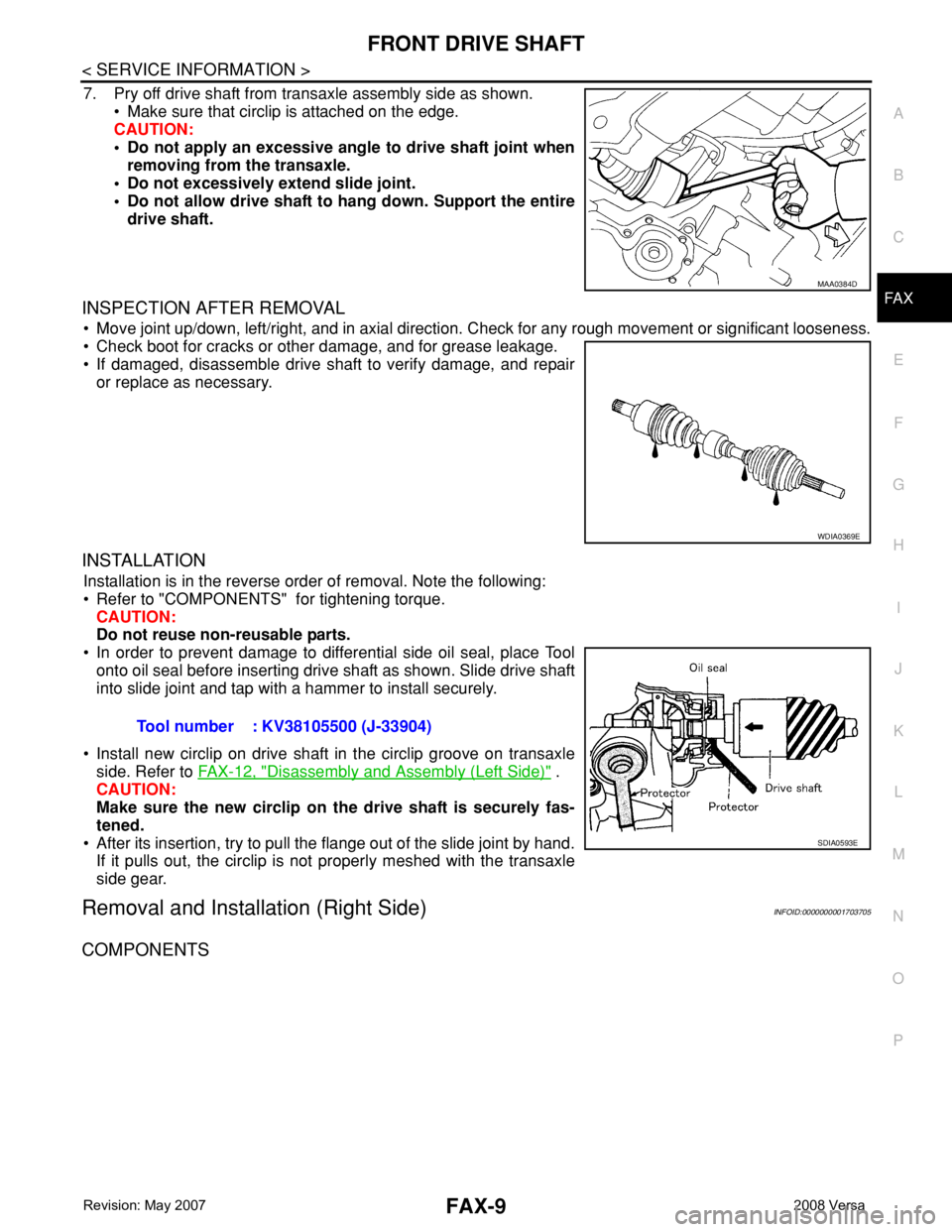
7. Pry off drive shaft from transaxle assembly side as shown.
• Make sure that circlip is attached on the edge.
CAUTION:
• Do not apply an excessive angle to drive shaft joint when
removing from the transaxle.
• Do not excessively extend slide joint.
• Do not allow drive shaft to hang down. Support the entire
drive shaft.
INSPECTION AFTER REMOVAL
• Move joint up/down, left/right, and in axial direction. Check for any rough movement or significant looseness.
• Check boot for cracks or other damage, and for grease leakage.
• If damaged, disassemble drive shaft to verify damage, and repair
or replace as necessary.
INSTALLATION
Installation is in the reverse order of removal. Note the following:
• Refer to "COMPONENTS" for tightening torque.
CAUTION:
Do not reuse non-reusable parts.
• In order to prevent damage to differential side oil seal, place Tool
onto oil seal before inserting drive shaft as shown. Slide drive shaft
into slide joint and tap with a hammer to install securely.
• Install new circlip on drive shaft in the circlip groove on transaxle
side. Refer to FAX-12, "
Disassembly and Assembly (Left Side)" .
CAUTION:
Make sure the new circlip on the drive shaft is securely fas-
tened.
• After its insertion, try to pull the flange out of the slide joint by hand.
If it pulls out, the circlip is not properly meshed with the transaxle
side gear.
Removal and Installation (Right Side)INFOID:0000000001703705
COMPONENTS
MAA0384D
WDIA0369E
Tool number : KV38105500 (J-33904)
SDIA0593E
Page 1807 of 2771
FRONT DRIVE SHAFT
FAX-11
< SERVICE INFORMATION >
C
E
F
G
H
I
J
K
L
MA
B
FA X
N
O
P
• Check boot for cracks or other damage, and for grease leakage.
• If damaged, disassemble drive shaft to verify damage, and repair
or replace as necessary.
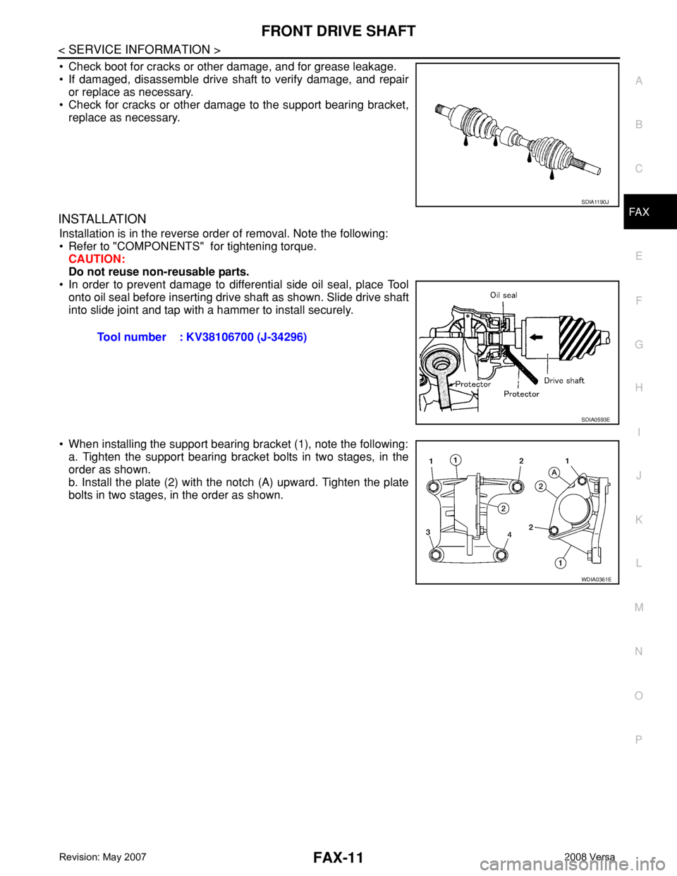
• Check for cracks or other damage to the support bearing bracket,
replace as necessary.
INSTALLATION
Installation is in the reverse order of removal. Note the following:
• Refer to "COMPONENTS" for tightening torque.
CAUTION:
Do not reuse non-reusable parts.
• In order to prevent damage to differential side oil seal, place Tool
onto oil seal before inserting drive shaft as shown. Slide drive shaft
into slide joint and tap with a hammer to install securely.
• When installing the support bearing bracket (1), note the following:
a. Tighten the support bearing bracket bolts in two stages, in the
order as shown.
b. Install the plate (2) with the notch (A) upward. Tighten the plate
bolts in two stages, in the order as shown.
SDIA1190J
Tool number : KV38106700 (J-34296)
SDIA0593E
WDIA0361E
Page 1832 of 2771
FL-12
< SERVICE INFORMATION >
FUEL TANK
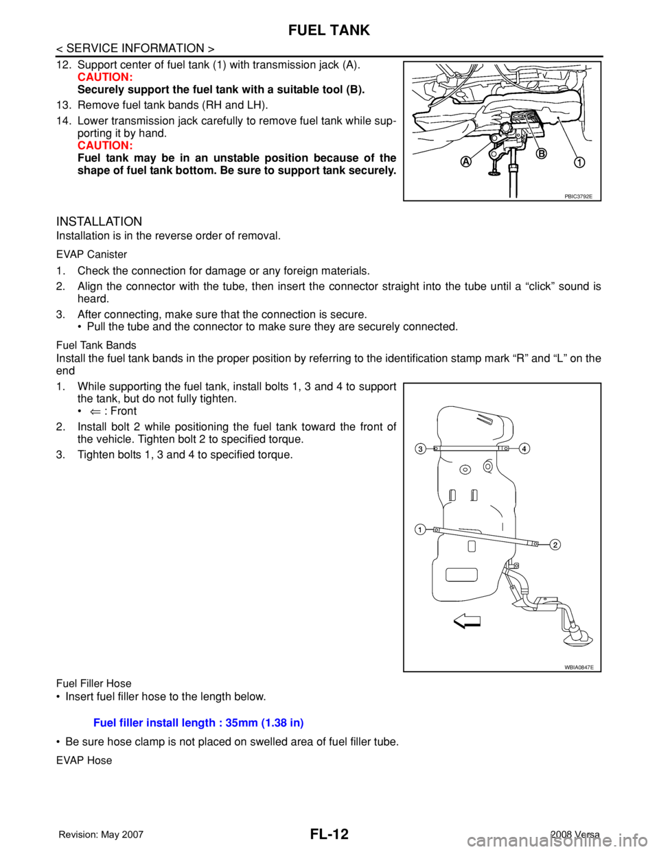
12. Support center of fuel tank (1) with transmission jack (A).
CAUTION:
Securely support the fuel tank with a suitable tool (B).
13. Remove fuel tank bands (RH and LH).
14. Lower transmission jack carefully to remove fuel tank while sup-
porting it by hand.
CAUTION:
Fuel tank may be in an unstable position because of the
shape of fuel tank bottom. Be sure to support tank securely.
INSTALLATION
Installation is in the reverse order of removal.
EVAP Canister
1. Check the connection for damage or any foreign materials.
2. Align the connector with the tube, then insert the connector straight into the tube until a “click” sound is
heard.
3. After connecting, make sure that the connection is secure.
• Pull the tube and the connector to make sure they are securely connected.
Fuel Tank Bands
Install the fuel tank bands in the proper position by referring to the identification stamp mark “R” and “L” on the
end
1. While supporting the fuel tank, install bolts 1, 3 and 4 to support
the tank, but do not fully tighten.
• ⇐ : Front
2. Install bolt 2 while positioning the fuel tank toward the front of
the vehicle. Tighten bolt 2 to specified torque.
3. Tighten bolts 1, 3 and 4 to specified torque.
Fuel Filler Hose
• Insert fuel filler hose to the length below.
• Be sure hose clamp is not placed on swelled area of fuel filler tube.
EVAP Hose
PBIC3792E
WBIA0847E
Fuel filler install length : 35mm (1.38 in)
Page 1837 of 2771
PREPARATION
FSU-3
< SERVICE INFORMATION >
C
D
F
G
H
I
J
K
L
MA
B
FSU
N
O
P
PREPARATION
Special Service ToolINFOID:0000000001703718
The actual shapes of Kent-Moore tools may differ from those of special tools illustrated here.
Tool number
(Kent-Moore No.)
Tool nameDescription
KV991040S0
(—)
CCK gauge attachment
1. Plate
2. Guide bolt
3. Nut
4. Spring
5. Center plate
6. KV99104020 Adapter A
a: 72 mm (2.83 in) dia.
7. KV99104030 Adapter B
b: 65 mm (2.56 in) dia.
8. KV99104040 Adapter C
c: 57 mm (2.24 in) dia.
9. KV99104050 Adapter D
d: 53.4 mm (2.102 in) dia.Measuring wheel alignment
ST35652000
(—)
Strut attachmentDisassembling and assembling strut
ST3127S000
(J-25742-1)
Preload Gauge
1. GG91030000
(J-25765)
Torque wrench
2. HT62940000
( — )
Socket adapter (1/2″)
3. HT62900000
( — )
Socket adapter (3/8″)Measuring rotating torque of ball joint
HT72520000
(J-25730-A)
Ball joint removerRemoving tie-rod outer end and lower
ball joint
S-NT498
ZZA0807D
NT124
NT146
Page 1844 of 2771
FSU-10
< SERVICE INFORMATION >
FRONT SUSPENSION ASSEMBLY
Removal and Installation
INFOID:0000000001703724
REMOVAL
1. Separate intermediate shaft from steering gear pinion shaft. Refer to PS-9, "Removal and Installation".
2. Remove front tires from vehicle using a power tool.
3. Remove wheel sensor from steering knuckle. Refer to BRC-32
.
CAUTION:
Do not pull on wheel sensor harness.
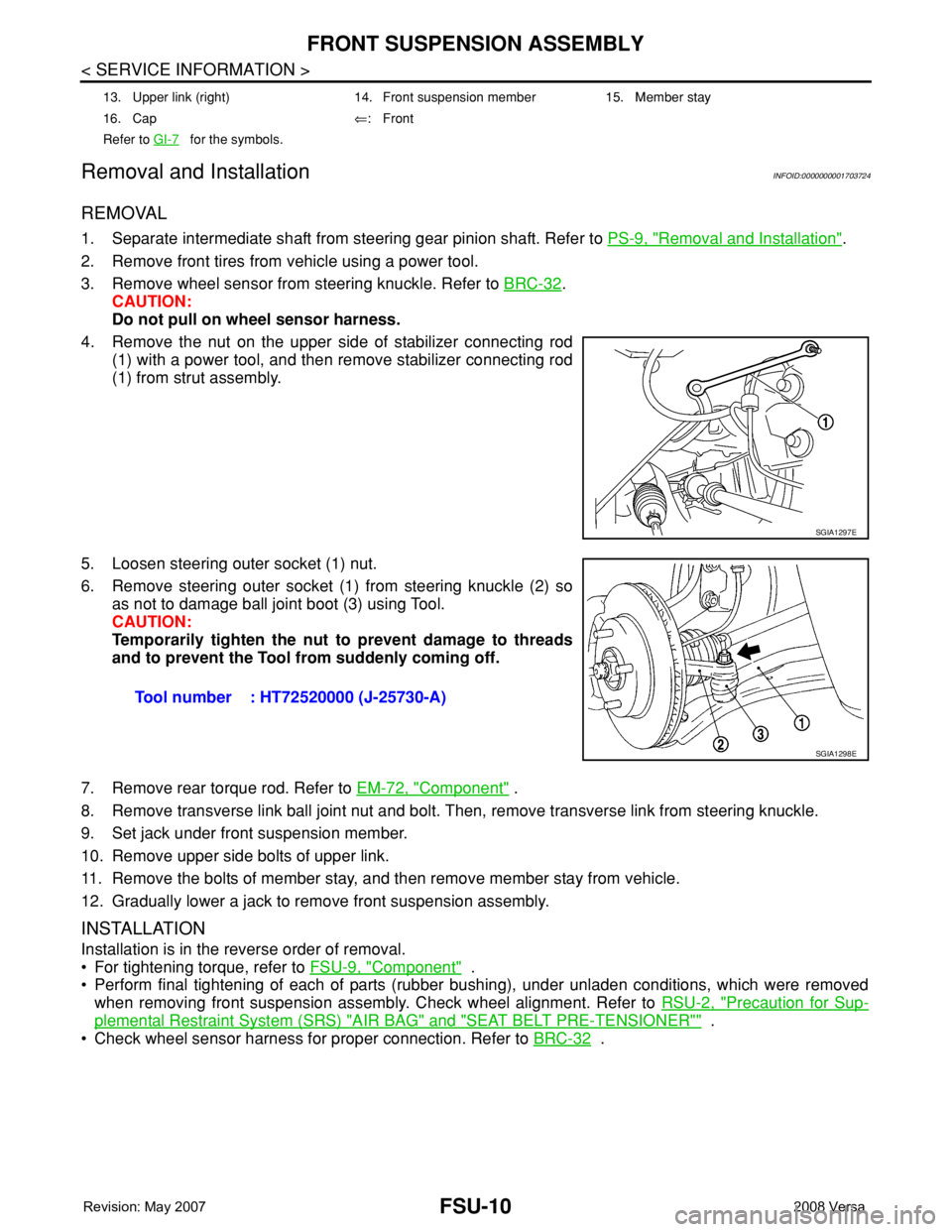
4. Remove the nut on the upper side of stabilizer connecting rod
(1) with a power tool, and then remove stabilizer connecting rod
(1) from strut assembly.
5. Loosen steering outer socket (1) nut.
6. Remove steering outer socket (1) from steering knuckle (2) so
as not to damage ball joint boot (3) using Tool.
CAUTION:
Temporarily tighten the nut to prevent damage to threads
and to prevent the Tool from suddenly coming off.
7. Remove rear torque rod. Refer to EM-72, "
Component" .
8. Remove transverse link ball joint nut and bolt. Then, remove transverse link from steering knuckle.
9. Set jack under front suspension member.
10. Remove upper side bolts of upper link.
11. Remove the bolts of member stay, and then remove member stay from vehicle.
12. Gradually lower a jack to remove front suspension assembly.
INSTALLATION
Installation is in the reverse order of removal.
• For tightening torque, refer to FSU-9, "
Component" .
• Perform final tightening of each of parts (rubber bushing), under unladen conditions, which were removed
when removing front suspension assembly. Check wheel alignment. Refer to RSU-2, "
Precaution for Sup-
plemental Restraint System (SRS) "AIR BAG" and "SEAT BELT PRE-TENSIONER"" .
• Check wheel sensor harness for proper connection. Refer to BRC-32
.
13. Upper link (right) 14. Front suspension member 15. Member stay
16. Cap⇐:Front
Refer to GI-7
for the symbols.
SGIA1297E
Tool number : HT72520000 (J-25730-A)
SGIA1298E