2008 NISSAN LATIO torque
[x] Cancel search: torquePage 2511 of 2771
NOISE, VIBRATION AND HARSHNESS (NVH) TROUBLESHOOTING
PS-5
< SERVICE INFORMATION >
C
D
E
F
H
I
J
K
L
MA
B
PS
N
O
P
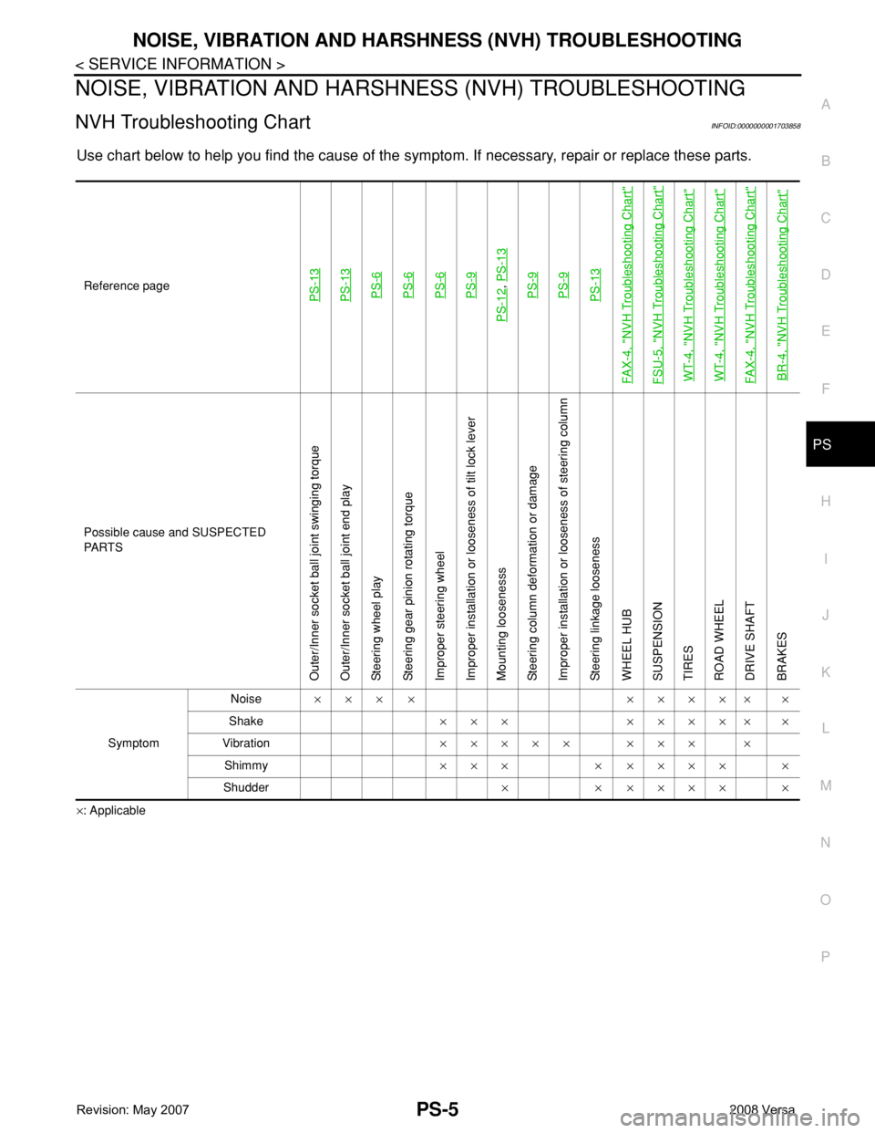
NOISE, VIBRATION AND HARSHNESS (NVH) TROUBLESHOOTING
NVH Troubleshooting ChartINFOID:0000000001703858
Use chart below to help you find the cause of the symptom. If necessary, repair or replace these parts.
×: ApplicableReference page
PS-13PS-13PS-6PS-6PS-6PS-9
PS-12
, PS-13PS-9PS-9PS-13
FAX-4, "
NVH Troubleshooting Chart
"
FSU-5, "
NVH Troubleshooting Chart
"
WT-4, "
NVH Troubleshooting Chart
"
WT-4, "
NVH Troubleshooting Chart
"
FAX-4, "
NVH Troubleshooting Chart
"
BR-4, "
NVH Troubleshooting Chart
"
Possible cause and SUSPECTED
PA R T S
Outer/Inner socket ball joint swinging torque
Outer/Inner socket ball joint end play
Steering wheel play
Steering gear pinion rotating torque
Improper steering wheel
Improper installation or looseness of tilt lock lever
Mounting loosenesss
Steering column deformation or damage
Improper installation or looseness of steering column
Steering linkage looseness
WHEEL HUB
SUSPENSION
TIRES
ROAD WHEEL
DRIVE SHAFT
BRAKES
SymptomNoise××× × ××××× ×
Shake××× ××××× ×
Vibration××××× ××× ×
Shimmy××× × ×××× ×
Shudder× × ×××× ×
Page 2516 of 2771
PS-10
< SERVICE INFORMATION >
STEERING COLUMN
8. Remove bolt of intermediate shaft (upper side), and then remove intermediate shaft from steering column
assembly.
9. Remove steering column assembly mounting nuts, and then remove steering column assembly from vehi-
cle.
10. Remove bolt of intermediate shaft (lower side), and then remove intermediate shaft from vehicle.
11. Remove screws of bracket and EPS control unit, and then remove bracket and EPS control unit from
steering column assembly.
INSPECTION AFTER REMOVAL
• Check each part of steering column assembly, EPS control unit and intermediate shaft for damage and .
replace as necessary.
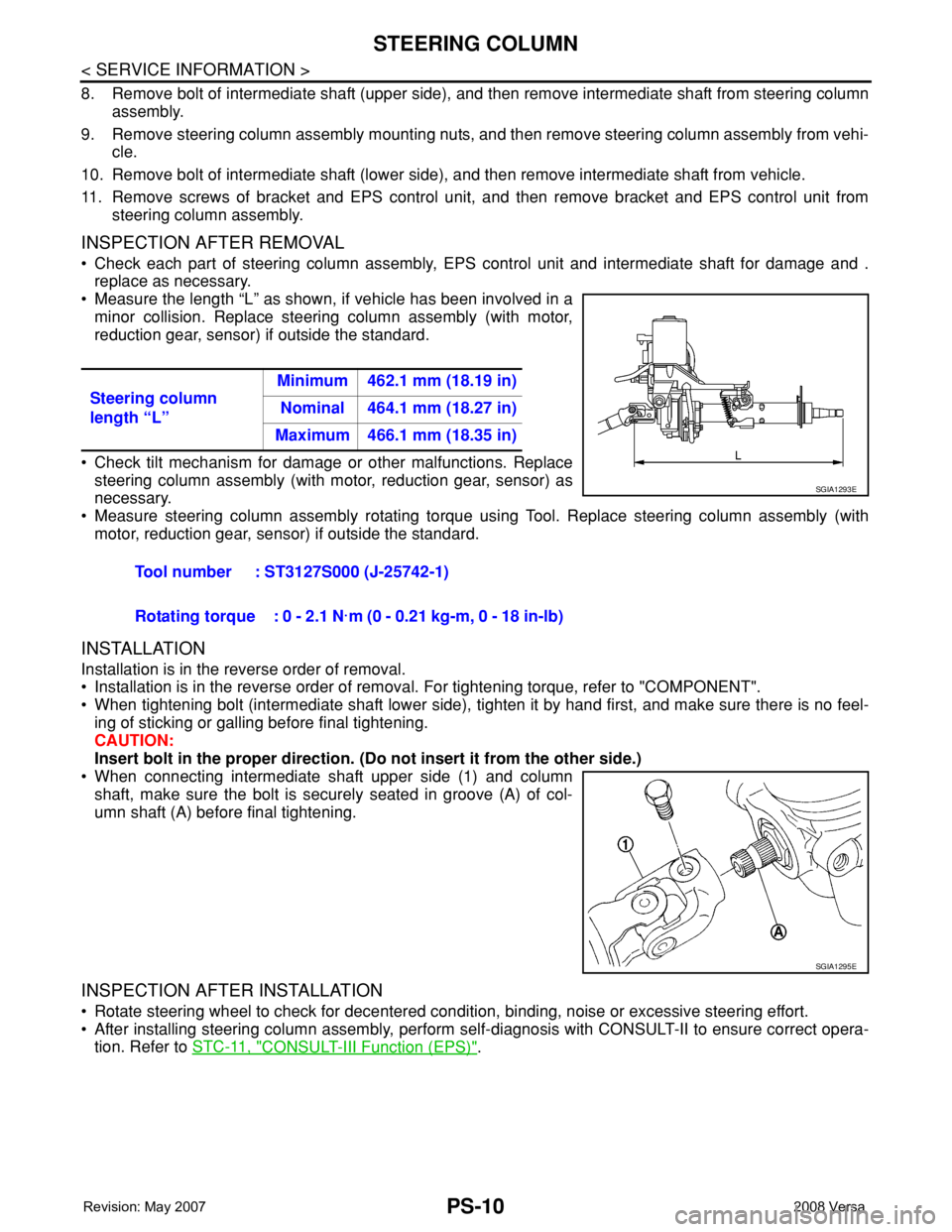
• Measure the length “L” as shown, if vehicle has been involved in a
minor collision. Replace steering column assembly (with motor,
reduction gear, sensor) if outside the standard.
• Check tilt mechanism for damage or other malfunctions. Replace
steering column assembly (with motor, reduction gear, sensor) as
necessary.
• Measure steering column assembly rotating torque using Tool. Replace steering column assembly (with
motor, reduction gear, sensor) if outside the standard.
INSTALLATION
Installation is in the reverse order of removal.
• Installation is in the reverse order of removal. For tightening torque, refer to "COMPONENT".
• When tightening bolt (intermediate shaft lower side), tighten it by hand first, and make sure there is no feel-
ing of sticking or galling before final tightening.
CAUTION:
Insert bolt in the proper direction. (Do not insert it from the other side.)
• When connecting intermediate shaft upper side (1) and column
shaft, make sure the bolt is securely seated in groove (A) of col-
umn shaft (A) before final tightening.
INSPECTION AFTER INSTALLATION
• Rotate steering wheel to check for decentered condition, binding, noise or excessive steering effort.
• After installing steering column assembly, perform self-diagnosis with CONSULT-II to ensure correct opera-
tion. Refer to STC-11, "
CONSULT-III Function (EPS)". Steering column
length “L”Minimum 462.1 mm (18.19 in)
Nominal 464.1 mm (18.27 in)
Maximum 466.1 mm (18.35 in)
Tool number : ST3127S000 (J-25742-1)
Rotating torque : 0 - 2.1 N·m (0 - 0.21 kg-m, 0 - 18 in-lb)
SGIA1293E
SGIA1295E
Page 2518 of 2771
PS-12
< SERVICE INFORMATION >
POWER STEERING GEAR
POWER STEERING GEAR
Removal and InstallationINFOID:0000000001703862
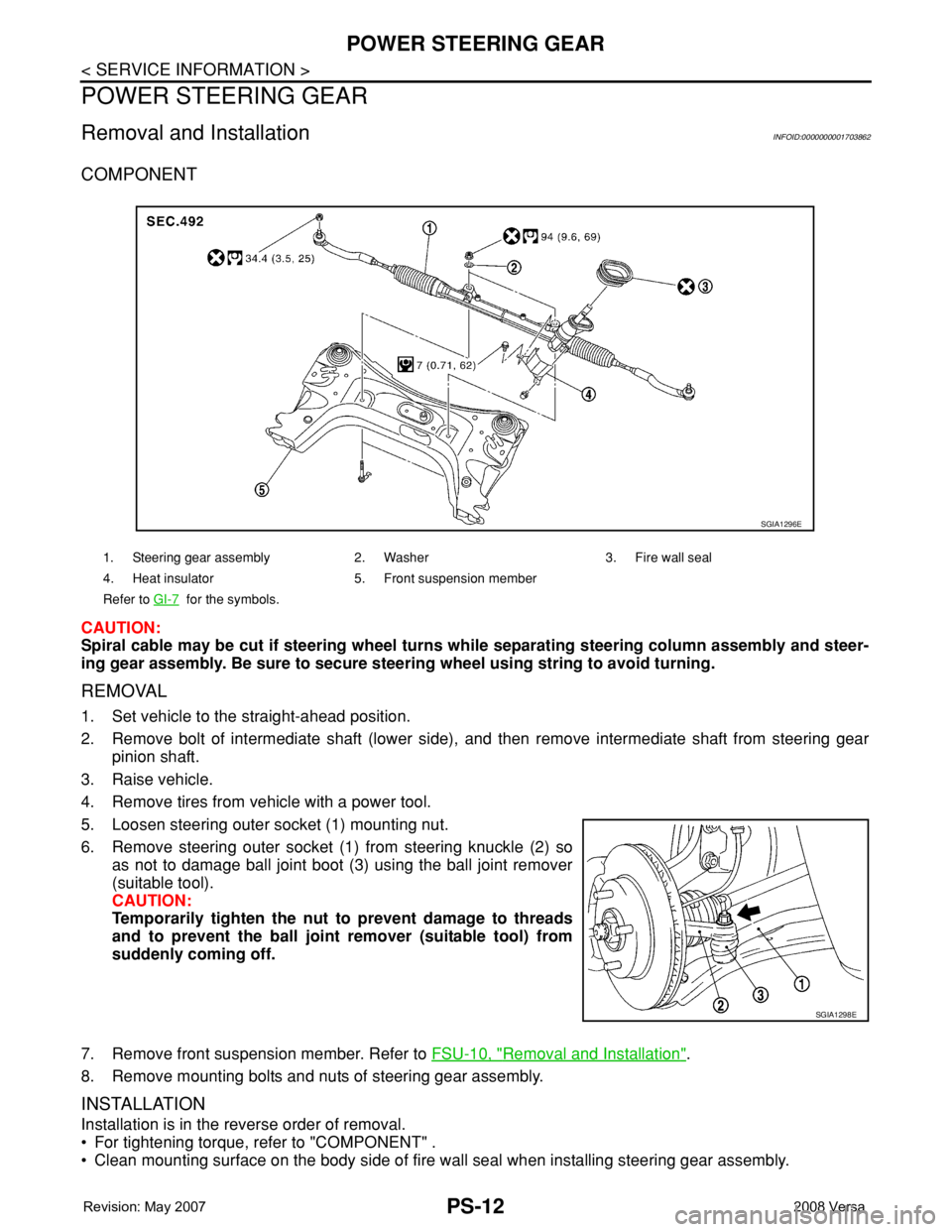
COMPONENT
CAUTION:
Spiral cable may be cut if steering wheel turns while separating steering column assembly and steer-
ing gear assembly. Be sure to secure steering wheel using string to avoid turning.
REMOVAL
1. Set vehicle to the straight-ahead position.
2. Remove bolt of intermediate shaft (lower side), and then remove intermediate shaft from steering gear
pinion shaft.
3. Raise vehicle.
4. Remove tires from vehicle with a power tool.
5. Loosen steering outer socket (1) mounting nut.
6. Remove steering outer socket (1) from steering knuckle (2) so
as not to damage ball joint boot (3) using the ball joint remover
(suitable tool).
CAUTION:
Temporarily tighten the nut to prevent damage to threads
and to prevent the ball joint remover (suitable tool) from
suddenly coming off.
7. Remove front suspension member. Refer to FSU-10, "
Removal and Installation".
8. Remove mounting bolts and nuts of steering gear assembly.
INSTALLATION
Installation is in the reverse order of removal.
• For tightening torque, refer to "COMPONENT" .
• Clean mounting surface on the body side of fire wall seal when installing steering gear assembly.
1. Steering gear assembly 2. Washer 3. Fire wall seal
4. Heat insulator 5. Front suspension member
Refer to GI-7
for the symbols.
SGIA1296E
SGIA1298E
Page 2520 of 2771
PS-14
< SERVICE INFORMATION >
POWER STEERING GEAR
3. Remove inner socket from rack assembly while holding the flat portion of the rack next to the inner socket
using a suitable tool.
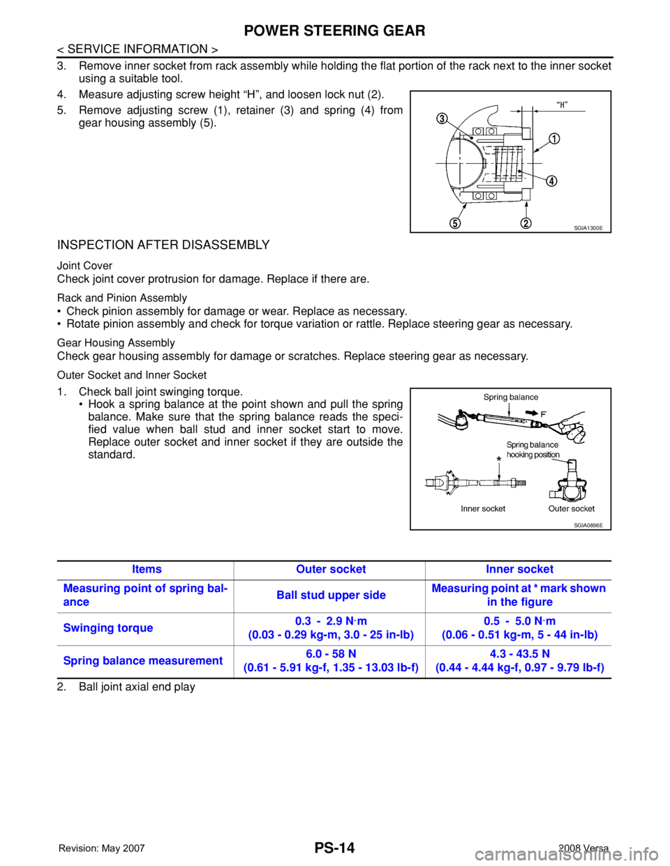
4. Measure adjusting screw height “H”, and loosen lock nut (2).
5. Remove adjusting screw (1), retainer (3) and spring (4) from
gear housing assembly (5).
INSPECTION AFTER DISASSEMBLY
Joint Cover
Check joint cover protrusion for damage. Replace if there are.
Rack and Pinion Assembly
• Check pinion assembly for damage or wear. Replace as necessary.
• Rotate pinion assembly and check for torque variation or rattle. Replace steering gear as necessary.
Gear Housing Assembly
Check gear housing assembly for damage or scratches. Replace steering gear as necessary.
Outer Socket and Inner Socket
1. Check ball joint swinging torque.
• Hook a spring balance at the point shown and pull the spring
balance. Make sure that the spring balance reads the speci-
fied value when ball stud and inner socket start to move.
Replace outer socket and inner socket if they are outside the
standard.
2. Ball joint axial end play
SGIA1300E
SGIA0896E
Items Outer socket Inner socket
Measuring point of spring bal-
anceBall stud upper sideMeasuring point at * mark shown
in the figure
Swinging torque0.3 - 2.9 N·m
(0.03 - 0.29 kg-m, 3.0 - 25 in-lb)0.5 - 5.0 N·m
(0.06 - 0.51 kg-m, 5 - 44 in-lb)
Spring balance measurement6.0 - 58 N
(0.61 - 5.91 kg-f, 1.35 - 13.03 lb-f)4.3 - 43.5 N
(0.44 - 4.44 kg-f, 0.97 - 9.79 lb-f)
Page 2521 of 2771
POWER STEERING GEAR
PS-15
< SERVICE INFORMATION >
C
D
E
F
H
I
J
K
L
MA
B
PS
N
O
P
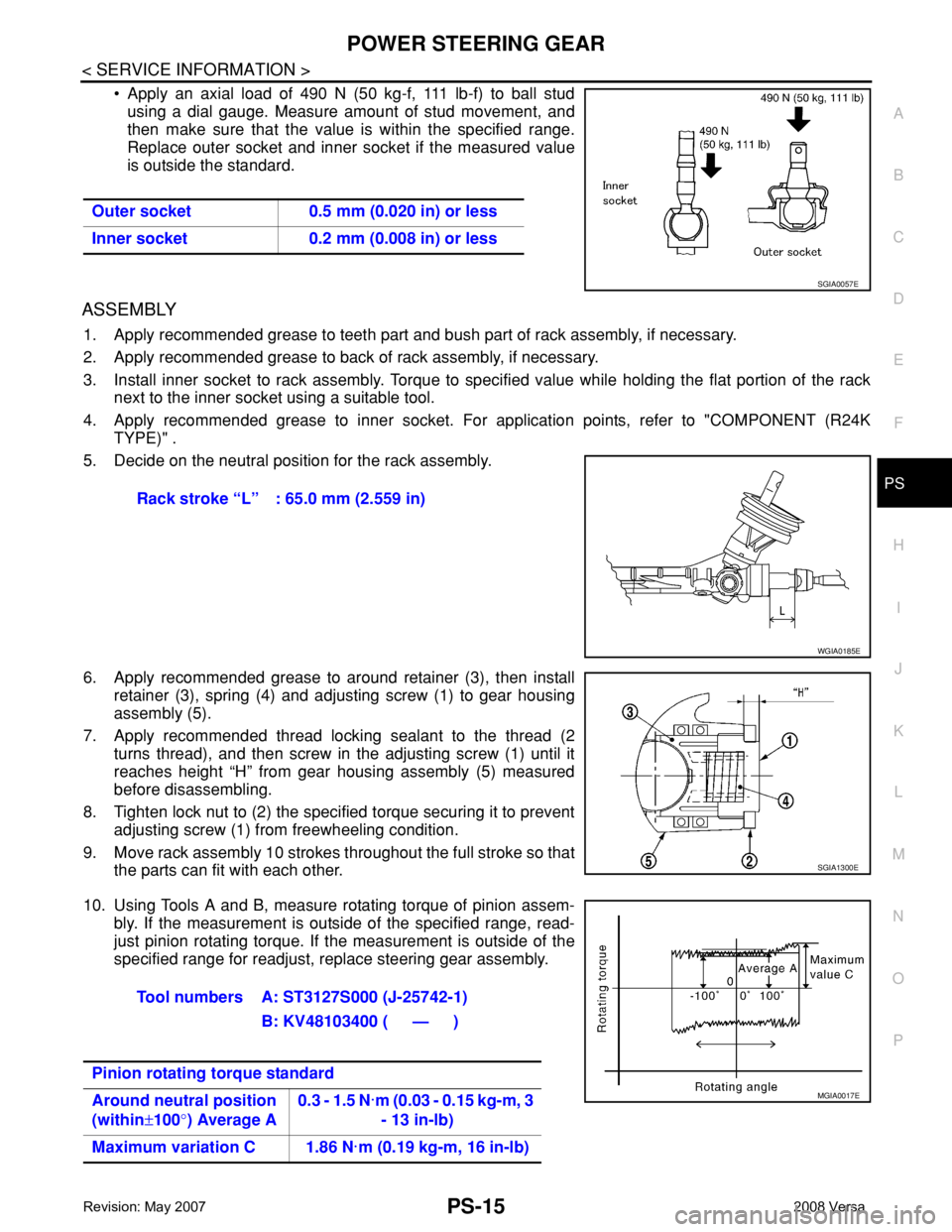
• Apply an axial load of 490 N (50 kg-f, 111 lb-f) to ball stud
using a dial gauge. Measure amount of stud movement, and
then make sure that the value is within the specified range.
Replace outer socket and inner socket if the measured value
is outside the standard.
ASSEMBLY
1. Apply recommended grease to teeth part and bush part of rack assembly, if necessary.
2. Apply recommended grease to back of rack assembly, if necessary.
3. Install inner socket to rack assembly. Torque to specified value while holding the flat portion of the rack
next to the inner socket using a suitable tool.
4. Apply recommended grease to inner socket. For application points, refer to "COMPONENT (R24K
TYPE)" .
5. Decide on the neutral position for the rack assembly.
6. Apply recommended grease to around retainer (3), then install
retainer (3), spring (4) and adjusting screw (1) to gear housing
assembly (5).
7. Apply recommended thread locking sealant to the thread (2
turns thread), and then screw in the adjusting screw (1) until it
reaches height “H” from gear housing assembly (5) measured
before disassembling.
8. Tighten lock nut to (2) the specified torque securing it to prevent
adjusting screw (1) from freewheeling condition.
9. Move rack assembly 10 strokes throughout the full stroke so that
the parts can fit with each other.
10. Using Tools A and B, measure rotating torque of pinion assem-
bly. If the measurement is outside of the specified range, read-
just pinion rotating torque. If the measurement is outside of the
specified range for readjust, replace steering gear assembly. Outer socket 0.5 mm (0.020 in) or less
Inner socket 0.2 mm (0.008 in) or less
SGIA0057E
Rack stroke “L” : 65.0 mm (2.559 in)
WGIA0185E
SGIA1300E
Tool numbers A: ST3127S000 (J-25742-1)
B: KV48103400 ( — )
Pinion rotating torque standard
Around neutral position
(within±100°) Average A0.3 - 1.5 N·m (0.03 - 0.15 kg-m, 3
- 13 in-lb)
Maximum variation C 1.86 N·m (0.19 kg-m, 16 in-lb)
MGIA0017E
Page 2522 of 2771
PS-16
< SERVICE INFORMATION >
POWER STEERING GEAR
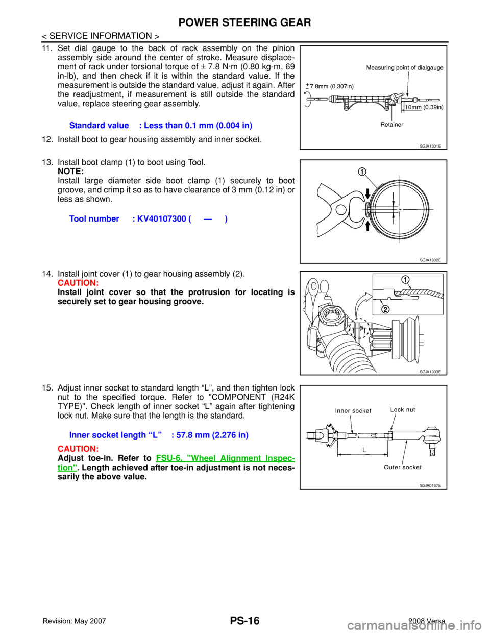
11. Set dial gauge to the back of rack assembly on the pinion
assembly side around the center of stroke. Measure displace-
ment of rack under torsional torque of ± 7.8 N·m (0.80 kg-m, 69
in-lb), and then check if it is within the standard value. If the
measurement is outside the standard value, adjust it again. After
the readjustment, if measurement is still outside the standard
value, replace steering gear assembly.
12. Install boot to gear housing assembly and inner socket.
13. Install boot clamp (1) to boot using Tool.
NOTE:
Install large diameter side boot clamp (1) securely to boot
groove, and crimp it so as to have clearance of 3 mm (0.12 in) or
less as shown.
14. Install joint cover (1) to gear housing assembly (2).
CAUTION:
Install joint cover so that the protrusion for locating is
securely set to gear housing groove.
15. Adjust inner socket to standard length “L”, and then tighten lock
nut to the specified torque. Refer to "COMPONENT (R24K
TYPE)". Check length of inner socket “L” again after tightening
lock nut. Make sure that the length is the standard.
CAUTION:
Adjust toe-in. Refer to FSU-6, "
Wheel Alignment Inspec-
tion". Length achieved after toe-in adjustment is not neces-
sarily the above value.Standard value : Less than 0.1 mm (0.004 in)
SGIA1301E
Tool number : KV40107300 ( — )
SGIA1302E
SGIA1303E
Inner socket length “L” : 57.8 mm (2.276 in)
SGIA0167E
Page 2523 of 2771
SERVICE DATA AND SPECIFICATIONS (SDS)
PS-17
< SERVICE INFORMATION >
C
D
E
F
H
I
J
K
L
MA
B
PS
N
O
P
SERVICE DATA AND SPECIFICATIONS (SDS)
Steering WheelINFOID:0000000001703864
Steering AngleINFOID:0000000001703865
Steering ColumnINFOID:0000000001703866
Steering Outer Socket and Inner SocketINFOID:0000000001703867
Steering wheel axial end play 0 mm (0 in)
Steering wheel play 0 - 35 mm (0 - 1.38 in)
Steering wheel turning force Less than 36 N (3.7 kg-f, 8.2 lb-f)
Inner wheel
Degree minute (Decimal degree)Minimum 35° 00′ (35.0°)
Nominal 38° 00′ (38.0°)
Maximum 39° 00′ (39.0°)
Outer wheel
Degree minute (Decimal degree)33° 00′ (33.0°)
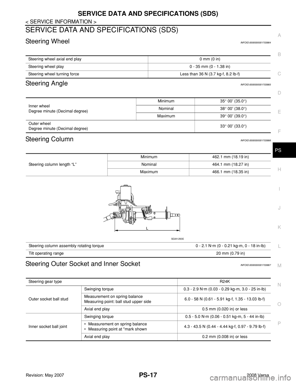
Steering column length “L”Minimum 462.1 mm (18.19 in)
Nominal 464.1 mm (18.27 in)
Maximum 466.1 mm (18.35 in)
Steering column assembly rotating torque 0 - 2.1 N·m (0 - 0.21 kg-m, 0 - 18 in-lb)
Tilt operating range20 mm (0.79 in)
SGIA1293E
Steering gear typeR24K
Outer socket ball studSwinging torque 0.3 - 2.9 N·m (0.03 - 0.29 kg-m, 3.0 - 25 in-lb)
Measurement on spring balance
Measuring point: ball stud upper side6.0 - 58 N (0.61 - 5.91 kg-f, 1.35 - 13.03 lb-f)
Axial end play 0.5 mm (0.020 in) or less
Inner socket ball jointSwinging torque 0.5 - 5.0 N·m (0.06 - 0.51 kg-m, 5 - 44 in-lb)
• Measurement on spring balance
• Measuring point at *mark shown4.3 - 43.5 N (0.44 - 4.44 kg-f, 0.97 - 9.79 lb-f)
Axial end play 0.2 mm (0.008 in) or less
Page 2524 of 2771
PS-18
< SERVICE INFORMATION >
SERVICE DATA AND SPECIFICATIONS (SDS)
Steering Gear
INFOID:0000000001703868
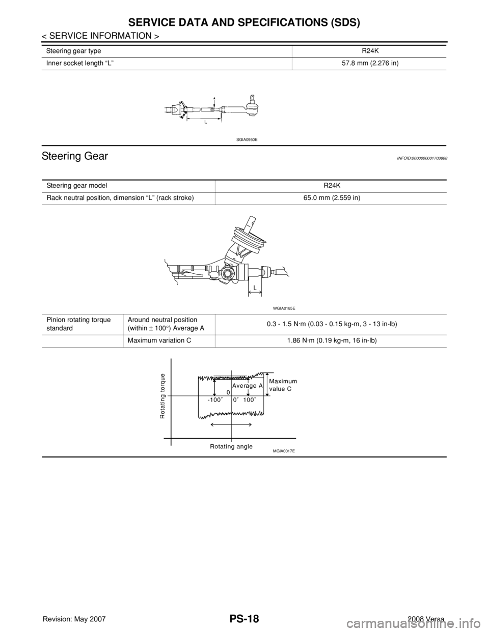
Inner socket length “L”57.8 mm (2.276 in) Steering gear typeR24K
SGIA0950E
Steering gear modelR24K
Rack neutral position, dimension “L” (rack stroke) 65.0 mm (2.559 in)
Pinion rotating torque
standardAround neutral position
(within ± 100°) Average A0.3 - 1.5 N·m (0.03 - 0.15 kg-m, 3 - 13 in-lb)
Maximum variation C 1.86 N·m (0.19 kg-m, 16 in-lb)
WGIA0185E
MGIA0017E