2008 NISSAN LATIO torque
[x] Cancel search: torquePage 2532 of 2771
RF-2
< PRECAUTION >
PRECAUTIONS
PRECAUTION
PRECAUTIONS
Precaution for Supplemental Restraint System (SRS) "AIR BAG" and "SEAT BELT
PRE-TENSIONER"
INFOID:0000000001704185
The Supplemental Restraint System such as “AIR BAG” and “SEAT BELT PRE-TENSIONER”, used along
with a front seat belt, helps to reduce the risk or severity of injury to the driver and front passenger for certain
types of collision. This system includes seat belt switch inputs and dual stage front air bag modules. The SRS
system uses the seat belt switches to determine the front air bag deployment, and may only deploy one front
air bag, depending on the severity of a collision and whether the front occupants are belted or unbelted.
Information necessary to service the system safely is included in the SR and SB section of this Service Man-
ual.
WARNING:
• To avoid rendering the SRS inoperative, which could increase the risk of personal injury or death in
the event of a collision which would result in air bag inflation, all maintenance must be performed by
an authorized NISSAN/INFINITI dealer.
• Improper maintenance, including incorrect removal and installation of the SRS, can lead to personal
injury caused by unintentional activation of the system. For removal of Spiral Cable and Air Bag
Module, see the SR section.
• Do not use electrical test equipment on any circuit related to the SRS unless instructed to in this
Service Manual. SRS wiring harnesses can be identified by yellow and/or orange harnesses or har-
ness connectors.
PrecautionINFOID:0000000001704186
• Disconnect both battery cables in advance.
• Do not tamper with or force air bag lid open, as this may adversely affect air bag performance.
• Be careful not to scratch pad and other parts.
• When removing or disassembling any part, be careful not to damage or deform it. Protect parts which may
get in the way with cloth.
• When removing parts with a screwdriver or other tool, protect parts by wrapping them with vinyl or tape.
• Keep removed parts protected with cloth.
• If a clip is deformed or damaged, replace it.
• If an unreusable part is removed, replace it with a new one.
• Tighten bolts and nuts firmly to the specified torque.
• After re-assembly has been completed, make sure each part functions correctly.
• Remove stains in the following way.
Water-soluble stains:
Dip a soft cloth in warm water, and then squeeze it tightly. After wiping the stain, wipe with a soft dry cloth.
Oil stain:
Dissolve a synthetic detergent in warm water (density of 2 to 3% or less), dip the cloth, then clean off the stain
with the cloth. Next, dip the cloth in fresh water and squeeze it tightly. Then clean off the detergent completely.
Then wipe the area with a soft dry cloth.
• Do not use any organic solvent, such as thinner or benzine.
Page 2555 of 2771
SUNROOF
RF-25
< ON-VEHICLE REPAIR >
C
D
E
F
G
H
J
K
L
MA
B
RF
N
O
P
1. Position the glass lid on sunroof unit assembly.
2. Partially install glass lid bolts. Tighten left front bolt first, then right rear to prevent uneven torque while
tightening remaining bolts.
3. After installation, check sunroof operation and glass lid assembly alignment. Refer to RF-26, "
Fitting
Adjustment" .
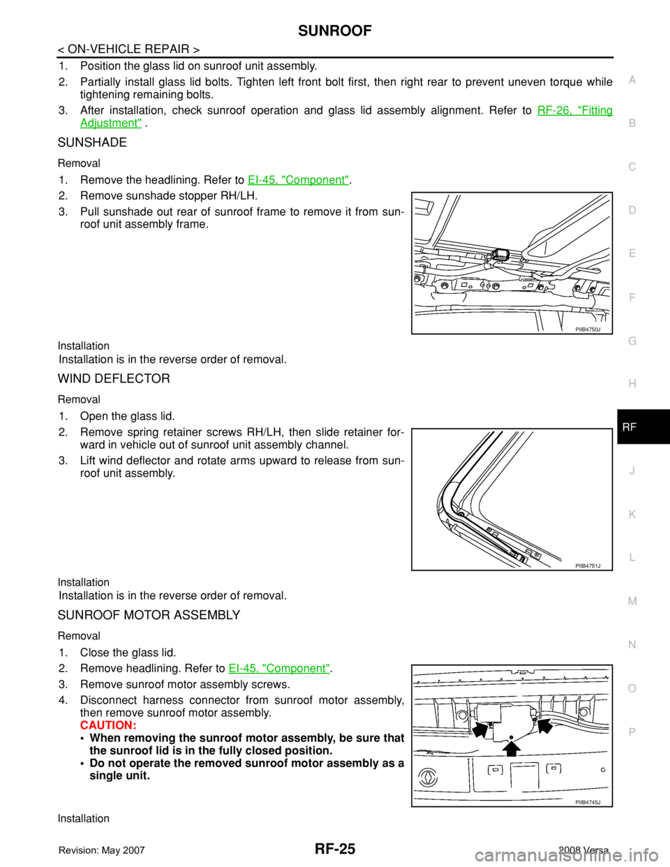
SUNSHADE
Removal
1. Remove the headlining. Refer to EI-45, "Component".
2. Remove sunshade stopper RH/LH.
3. Pull sunshade out rear of sunroof frame to remove it from sun-
roof unit assembly frame.
Installation
Installation is in the reverse order of removal.
WIND DEFLECTOR
Removal
1. Open the glass lid.
2. Remove spring retainer screws RH/LH, then slide retainer for-
ward in vehicle out of sunroof unit assembly channel.
3. Lift wind deflector and rotate arms upward to release from sun-
roof unit assembly.
Installation
Installation is in the reverse order of removal.
SUNROOF MOTOR ASSEMBLY
Removal
1. Close the glass lid.
2. Remove headlining. Refer to EI-45, "
Component".
3. Remove sunroof motor assembly screws.
4. Disconnect harness connector from sunroof motor assembly,
then remove sunroof motor assembly.
CAUTION:
• When removing the sunroof motor assembly, be sure that
the sunroof lid is in the fully closed position.
• Do not operate the removed sunroof motor assembly as a
single unit.
Installation
PIIB4750J
PIIB4751J
PIIB4745J
Page 2556 of 2771
RF-26
< ON-VEHICLE REPAIR >
SUNROOF
CAUTION:
• Before installing the sunroof motor assembly, be sure the link assembly is in the symmetrical and
fully closed position.
• Align the link notch with the hole of the guide track (fully closed: RH and LH).
1. Place the sunroof motor assembly flat onto the sunroof unit assembly surface.
2. Laterally move the assembly little by little so that the gear is completely engaged into the wire and there is
no gap between the sunroof unit assembly and sunroof motor assembly.
3. Install the sunroof motor assembly screws, then connect the harness connector.
4. After installing, perform the initialization procedure. Refer to RF-10, "
System Description" .
LINK ASSEMBLY
Removal
1. Remove sunroof unit assembly. Refer to RF-21, "Removal and Installation".
2. Remove screws, then remove rear drain assembly.
3. Remove sunroof motor assembly. Refer to RF-21, "
Removal and Installation".
4. Remove link assembly from the rear end of the sunroof frame.
Installation
Installation is in the reverse order of removal.
Fitting AdjustmentINFOID:0000000001704208
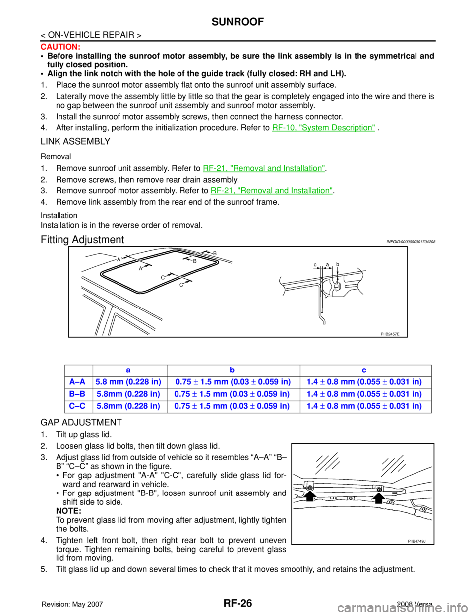
GAP ADJUSTMENT
1. Tilt up glass lid.
2. Loosen glass lid bolts, then tilt down glass lid.
3. Adjust glass lid from outside of vehicle so it resembles “A–A” “B–
B” “C–C” as shown in the figure.
• For gap adjustment "A-A" "C-C", carefully slide glass lid for-
ward and rearward in vehicle.
• For gap adjustment "B-B", loosen sunroof unit assembly and
shift side to side.
NOTE:
To prevent glass lid from moving after adjustment, lightly tighten
the bolts.
4. Tighten left front bolt, then right rear bolt to prevent uneven
torque. Tighten remaining bolts, being careful to prevent glass
lid from moving.
5. Tilt glass lid up and down several times to check that it moves smoothly, and retains the adjustment.
PIIB2457E
ab c
A–A 5.8 mm (0.228 in) 0.75 ± 1.5 mm (0.03 ± 0.059 in) 1.4 ± 0.8 mm (0.055 ± 0.031 in)
B–B 5.8mm (0.228 in) 0.75 ± 1.5 mm (0.03 ± 0.059 in) 1.4 ± 0.8 mm (0.055 ± 0.031 in)
C–C 5.8mm (0.228 in) 0.75 ± 1.5 mm (0.03 ± 0.059 in) 1.4 ± 0.8 mm (0.055 ± 0.031 in)
PIIB4749J
Page 2557 of 2771
SUNROOF
RF-27
< ON-VEHICLE REPAIR >
C
D
E
F
G
H
J
K
L
MA
B
RF
N
O
P
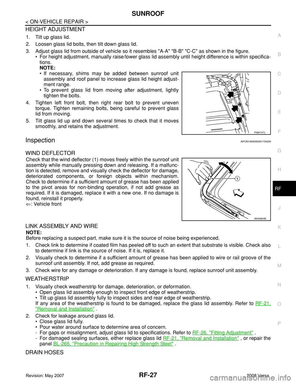
HEIGHT ADJUSTMENT
1. Tilt up glass lid.
2. Loosen glass lid bolts, then tilt down glass lid.
3. Adjust glass lid from outside of vehicle so it resembles "A-A" "B-B" "C-C" as shown in the figure.
• For height adjustment, manually raise/lower glass lid assembly until height difference is within specifica-
tions.
NOTE:
• If necessary, shims may be added between sunroof unit
assembly and roof panel to increase glass lid height adjust-
ment range.
• To prevent glass lid from moving after adjustment, lightly
tighten the bolts.
4. Tighten left front bolt, then right rear bolt to prevent uneven
torque. Tighten remaining bolts, being careful to prevent glass
lid from moving.
5. Tilt glass lid up and down several times to check that it moves
smoothly, and retains the adjustment.
InspectionINFOID:0000000001704209
WIND DEFLECTOR
Check that the wind deflector (1) moves freely within the sunroof unit
assembly while manually pressing down and releasing. If a malfunc-
tion is detected, remove and visually check the deflector for damage,
deteriorated components, or foreign objects within mechanism.
Check to determine if a sufficient amount of grease has been applied
to the pivot areas for non-binding operation, if not add grease as
required. If it is damaged, replace it with a new one. If no damage is
found, reinstall it properly.
⇐: Vehicle front
LINK ASSEMBLY AND WIRE
NOTE:
Before replacing a suspect part, make sure it is the source of noise being experienced.
1. Check link to determine if coated film has peeled off to such an extent that substrate is visible. Check also
to determine if link is the source of noise. If it is, replace it.
2. Visually check to determine if a sufficient amount of grease has been applied to wire or rail groove of the
sunroof unit assembly. If not, add grease as required.
3. Check wire for any damage or deterioration. If any damage is found, replace sunroof unit assembly.
WEATHERSTRIP
1. Visually check weatherstrip for damage, deterioration, or deformation.
• Open glass lid assembly enough to inspect front edge of weatherstrip.
• Tilt up glass lid assembly fully to inspect sides and rear edge of weatherstrip.
If any area of the weatherstrip is found to be damaged, replace the glass lid assembly. Refer to RF-21,
"Removal and Installation" .
2. Check for leakage around glass lid.
• Close glass lid fully.
• Pour water around surface to determine area of concern.
- For gaps or misalignment, adjust glass lid to specifications. Refer to RF-26, "
Fitting Adjustment" .
- For damaged sealing surfaces, either replace glass lid RF-21, "
Removal and Installation" , or repair the
panel BL-265, "
Precaution in Repairing High Strength Steel" .
DRAIN HOSES
PIIB4747J
WIIA0849E
Page 2567 of 2771
RSU-8
< SERVICE INFORMATION >
SHOCK ABSORBER
SHOCK ABSORBER
Removal and InstallationINFOID:0000000001703739
REMOVAL
1. Remove rear tires from vehicle using power tool.
2. Remove wheel sensor from wheel hub and bearing assembly and rear suspension beam. Refer to BRC-
32 .
CAUTION:
Do not pull on wheel sensor harness.
3. Remove shock absorber mask from trunk side finisher using a flat-bladed screwdriver. Refer to EI-51
.
CAUTION:
Wrap the tip of a screwdriver with cloth to avoid damaging components.
4. Set jack under rear suspension beam.
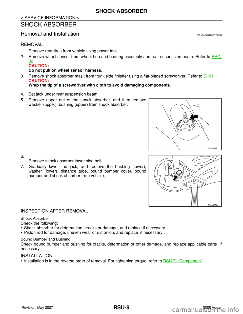
5. Remove upper nut of the shock absorber, and then remove
washer (upper), bushing (upper) from shock absorber.
6.
Remove shock absorber lower side bolt.
7. Gradually lower the jack, and remove the bushing (lower),
washer (lower), distance tube, bound bumper cover, bound
bumper and shock absorber from vehicle.
INSPECTION AFTER REMOVAL
Shock Absorber
Check the following:
• Shock absorber for deformation, cracks or damage, and replace if necessary.
• Piston rod for damage, uneven wear or distortion, and replace if necessary .
Bound Bumper and Bushing
Check bound bumper and bushing for cracks, deformation or other damage, and replace applicable parts if
necessary .
INSTALLATION
• Installation is in the reverse order of removal. For tightening torque, refer to RSU-7, "Component" .
SEIA0147J
SEIA0146J
Page 2569 of 2771
RSU-10
< SERVICE INFORMATION >
COIL SPRING
COIL SPRING
Removal and InstallationINFOID:0000000001703740
REMOVAL
1. Remove rear tires from vehicle using power tool.
2. Remove wheel sensor from wheel hub and bearing assembly. Refer to BRC-32
.
CAUTION:
Do not pull on wheel sensor harness.
3. Separate brake tube from wheel cylinder. Refer to BR-10
.
4. Set jack under rear suspension beam.
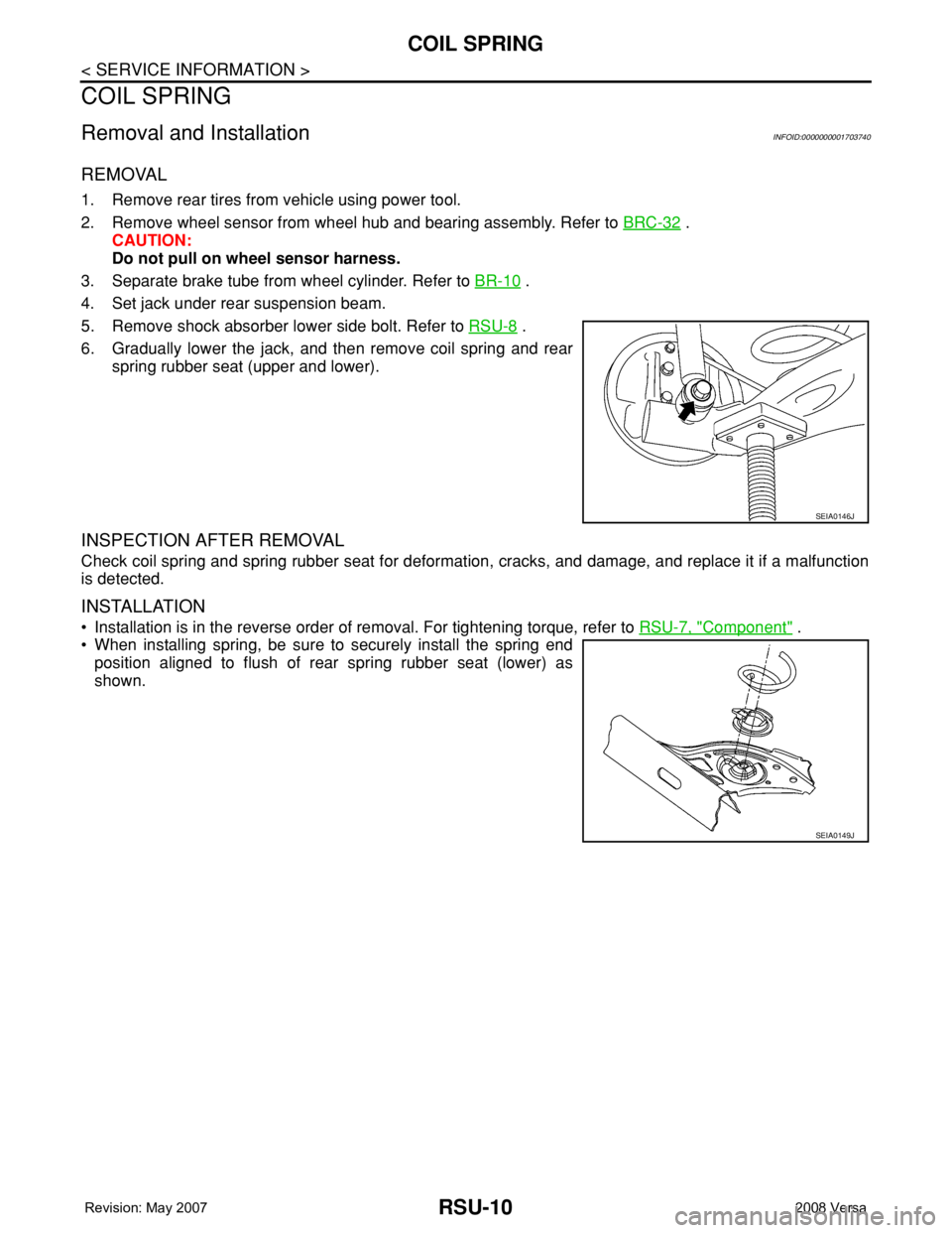
5. Remove shock absorber lower side bolt. Refer to RSU-8
.
6. Gradually lower the jack, and then remove coil spring and rear
spring rubber seat (upper and lower).
INSPECTION AFTER REMOVAL
Check coil spring and spring rubber seat for deformation, cracks, and damage, and replace it if a malfunction
is detected.
INSTALLATION
• Installation is in the reverse order of removal. For tightening torque, refer to RSU-7, "Component" .
• When installing spring, be sure to securely install the spring end
position aligned to flush of rear spring rubber seat (lower) as
shown.
SEIA0146J
SEIA0149J
Page 2570 of 2771
REAR SUSPENSION BEAM
RSU-11
< SERVICE INFORMATION >
C
D
F
G
H
I
J
K
L
MA
B
RSU
N
O
P
REAR SUSPENSION BEAM
Removal and InstallationINFOID:0000000001703741
REMOVAL
1. Remove rear tires from vehicle using power tool.
2. Separate parking brake rear cable from rear drum brake and rear suspension beam. Refer to PB-4
.
3. Remove wheel sensor and wheel sensor harness from wheel hub and bearing assembly and rear suspen-
sion beam. Refer to BRC-32
.
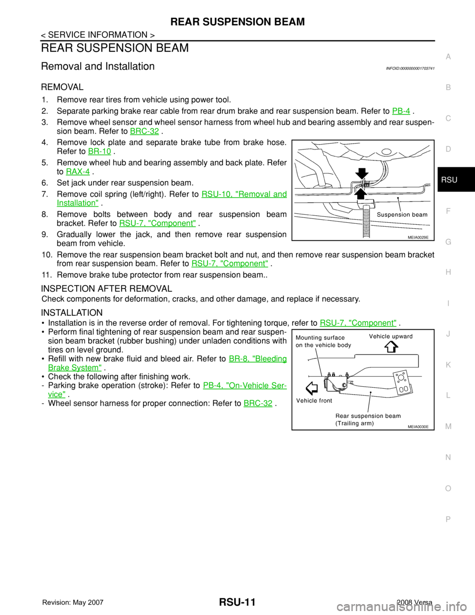
4. Remove lock plate and separate brake tube from brake hose.
Refer to BR-10
.
5. Remove wheel hub and bearing assembly and back plate. Refer
to RAX-4
.
6. Set jack under rear suspension beam.
7. Remove coil spring (left/right). Refer to RSU-10, "
Removal and
Installation" .
8. Remove bolts between body and rear suspension beam
bracket. Refer to RSU-7, "
Component" .
9. Gradually lower the jack, and then remove rear suspension
beam from vehicle.
10. Remove the rear suspension beam bracket bolt and nut, and then remove rear suspension beam bracket
from rear suspension beam. Refer to RSU-7, "
Component" .
11. Remove brake tube protector from rear suspension beam..
INSPECTION AFTER REMOVAL
Check components for deformation, cracks, and other damage, and replace if necessary.
INSTALLATION
• Installation is in the reverse order of removal. For tightening torque, refer to RSU-7, "Component" .
• Perform final tightening of rear suspension beam and rear suspen-
sion beam bracket (rubber bushing) under unladen conditions with
tires on level ground.
• Refill with new brake fluid and bleed air. Refer to BR-8, "
Bleeding
Brake System" .
• Check the following after finishing work.
- Parking brake operation (stroke): Refer to PB-4, "
On-Vehicle Ser-
vice" .
- Wheel sensor harness for proper connection: Refer to BRC-32
.
MEIA0029E
MEIA0030E
Page 2610 of 2771
SE-2
< SERVICE INFORMATION >
PRECAUTIONS
SERVICE INFORMATION
PRECAUTIONS
Precaution for Supplemental Restraint System (SRS) "AIR BAG" and "SEAT BELT
PRE-TENSIONER"
INFOID:0000000001704254
The Supplemental Restraint System such as “AIR BAG” and “SEAT BELT PRE-TENSIONER”, used along
with a front seat belt, helps to reduce the risk or severity of injury to the driver and front passenger for certain
types of collision. Information necessary to service the system safely is included in the SR and SB section of
this Service Manual.
WARNING:
• To avoid rendering the SRS inoperative, which could increase the risk of personal injury or death in
the event of a collision which would result in air bag inflation, all maintenance must be performed by
an authorized NISSAN/INFINITI dealer.
• Improper maintenance, including incorrect removal and installation of the SRS, can lead to personal
injury caused by unintentional activation of the system. For removal of Spiral Cable and Air Bag
Module, see the SR section.
• Do not use electrical test equipment on any circuit related to the SRS unless instructed to in this
Service Manual. SRS wiring harnesses can be identified by yellow and/or orange harnesses or har-
ness connectors.
Service NoticeINFOID:0000000001704255
• When removing or installing various parts, place a cloth or padding onto the vehicle body to prevent
scratches.
• Handle trim, molding instruments, grille, etc. carefully during removing or installing. Be careful not to oil or
damage them.
• Apply sealing compound where necessary when installing parts.
• When applying sealing compound, be careful that the sealing compound does not protrude from parts.
• When replacing any metal parts (for example body outer panel, member, etc.), be sure to take rust preven-
tion measures.
PrecautionINFOID:0000000001704256
• When removing or disassembling any part, be careful not to damage or deform it. Protect parts which may
get in the way with cloth.
• When removing parts with a screwdriver or other tool, protect parts by wrapping tools with vinyl or tape.
• Keep removed parts protected with cloth.
• If a clip is deformed or damaged, replace it.
• If an unreusable part is removed, replace it with a new one.
• Tighten bolts and nuts firmly to the specified torque.
• After re-assembly has been completed, make sure each part functions correctly.
• Remove stains in the following way.
Water-soluble stains:
Dip a soft cloth in warm water, and then squeeze it tightly. After wiping the stain, wipe with a soft dry cloth.
Oil stain:
Dissolve a synthetic detergent in warm water (density of 2 to 3% or less), dip the cloth, then clean off the stain
with the cloth. Next, dip the cloth in fresh water and squeeze it tightly. Then clean off the detergent completely.
Then wipe the area with a soft dry cloth.
• Do not use any organic solvent, such as thinner or benzine.