2008 NISSAN LATIO torque
[x] Cancel search: torquePage 1751 of 2771
EM-74
< SERVICE INFORMATION >
ENGINE ASSEMBLY
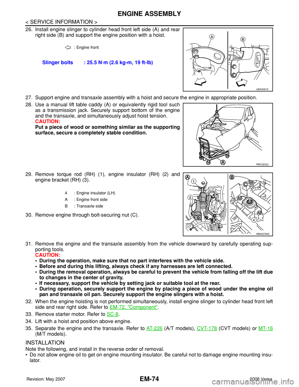
26. Install engine slinger to cylinder head front left side (A) and rear
right side (B) and support the engine position with a hoist.
27. Support engine and transaxle assembly with a hoist and secure the engine in appropriate position.
28. Use a manual lift table caddy (A) or equivalently rigid tool such
as a transmission jack. Securely support bottom of the engine
and the transaxle, and simultaneously adjust hoist tension.
CAUTION:
Put a piece of wood or something similar as the supporting
surface, secure a completely stable condition.
29. Remove torque rod (RH) (1), engine insulator (RH) (2) and
engine bracket (RH) (3).
30. Remove engine through bolt-securing nut (C).
31. Remove the engine and the transaxle assembly from the vehicle downward by carefully operating sup-
porting tools.
CAUTION:
• During the operation, make sure that no part interferes with the vehicle side.
• Before and during this lifting, always check if any harnesses are left connected.
• During the removal operation, always be careful to prevent the vehicle from falling off the lift due
to changes in the center of gravity.
• If necessary, support the vehicle by setting jack or suitable tool at the rear.
• During operation, securely support the engine by placing a piece of wood under the engine oil
pan and transaxle oil pan. Securely support the engine slingers with a hoist.
32. When the engine hoisting is not performed simultaneously, install engine slinger to cylinder head front left
side and rear right side. Refer to EM-72, "
Component".
33. Remove starter motor. Refer to SC-8
.
34. Lift with a hoist and position above engine.
35. Separate the engine and the transaxle. Refer to AT-226
(A/T models), CVT-178 (CVT models) or MT-16
(M/T models).
INSTALLATION
Note the following, and install in the reverse order of removal.
• Do not allow engine oil to get on engine mounting insulator. Be careful not to damage engine mounting insu-
lator.
: Engine front
Slinger bolts : 25.5 N·m (2.6 kg-m, 19 ft-lb)
LBIA0461E
PBIC3223J
4 : Engine insulator (LH)
A : Engine front side
B : Transaxle side
WBIA0784E
Page 1752 of 2771
ENGINE ASSEMBLY
EM-75
< SERVICE INFORMATION >
C
D
E
F
G
H
I
J
K
L
MA
EM
N
P O
• When installation directions are specified, install parts according to the directions. Refer to EM-72, "Compo-
nent".
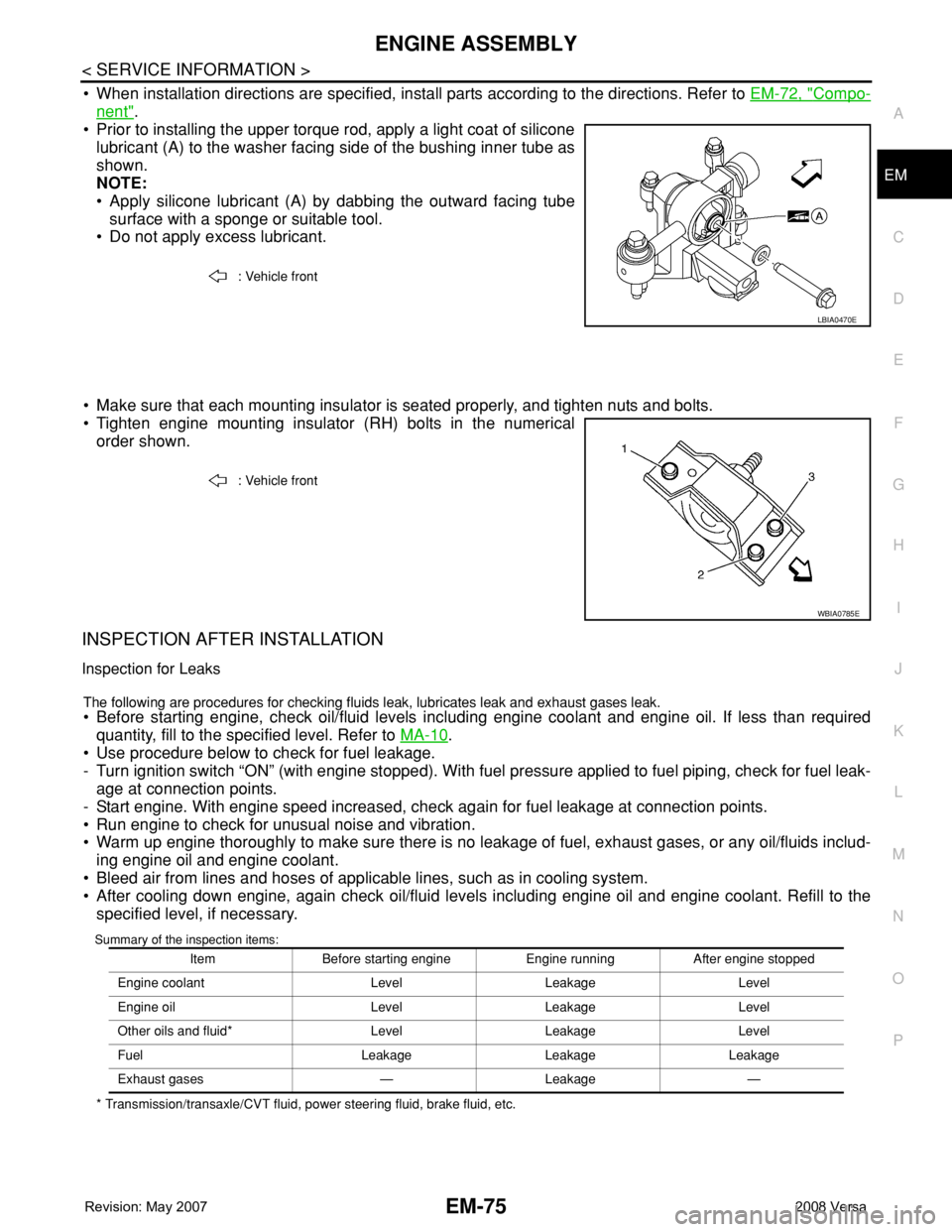
• Prior to installing the upper torque rod, apply a light coat of silicone
lubricant (A) to the washer facing side of the bushing inner tube as
shown.
NOTE:
• Apply silicone lubricant (A) by dabbing the outward facing tube
surface with a sponge or suitable tool.
• Do not apply excess lubricant.
• Make sure that each mounting insulator is seated properly, and tighten nuts and bolts.
• Tighten engine mounting insulator (RH) bolts in the numerical
order shown.
INSPECTION AFTER INSTALLATION
Inspection for Leaks
The following are procedures for checking fluids leak, lubricates leak and exhaust gases leak.
• Before starting engine, check oil/fluid levels including engine coolant and engine oil. If less than required
quantity, fill to the specified level. Refer to MA-10
.
• Use procedure below to check for fuel leakage.
- Turn ignition switch “ON” (with engine stopped). With fuel pressure applied to fuel piping, check for fuel leak-
age at connection points.
- Start engine. With engine speed increased, check again for fuel leakage at connection points.
• Run engine to check for unusual noise and vibration.
• Warm up engine thoroughly to make sure there is no leakage of fuel, exhaust gases, or any oil/fluids includ-
ing engine oil and engine coolant.
• Bleed air from lines and hoses of applicable lines, such as in cooling system.
• After cooling down engine, again check oil/fluid levels including engine oil and engine coolant. Refill to the
specified level, if necessary.
Summary of the inspection items:
* Transmission/transaxle/CVT fluid, power steering fluid, brake fluid, etc.: Vehicle front
LBIA0470E
: Vehicle front
WBIA0785E
Item Before starting engine Engine running After engine stopped
Engine coolant Level Leakage Level
Engine oil Level Leakage Level
Other oils and fluid* Level Leakage Level
Fuel Leakage Leakage Leakage
Exhaust gases — Leakage —
Page 1773 of 2771
EM-96
< SERVICE INFORMATION >
CYLINDER BLOCK
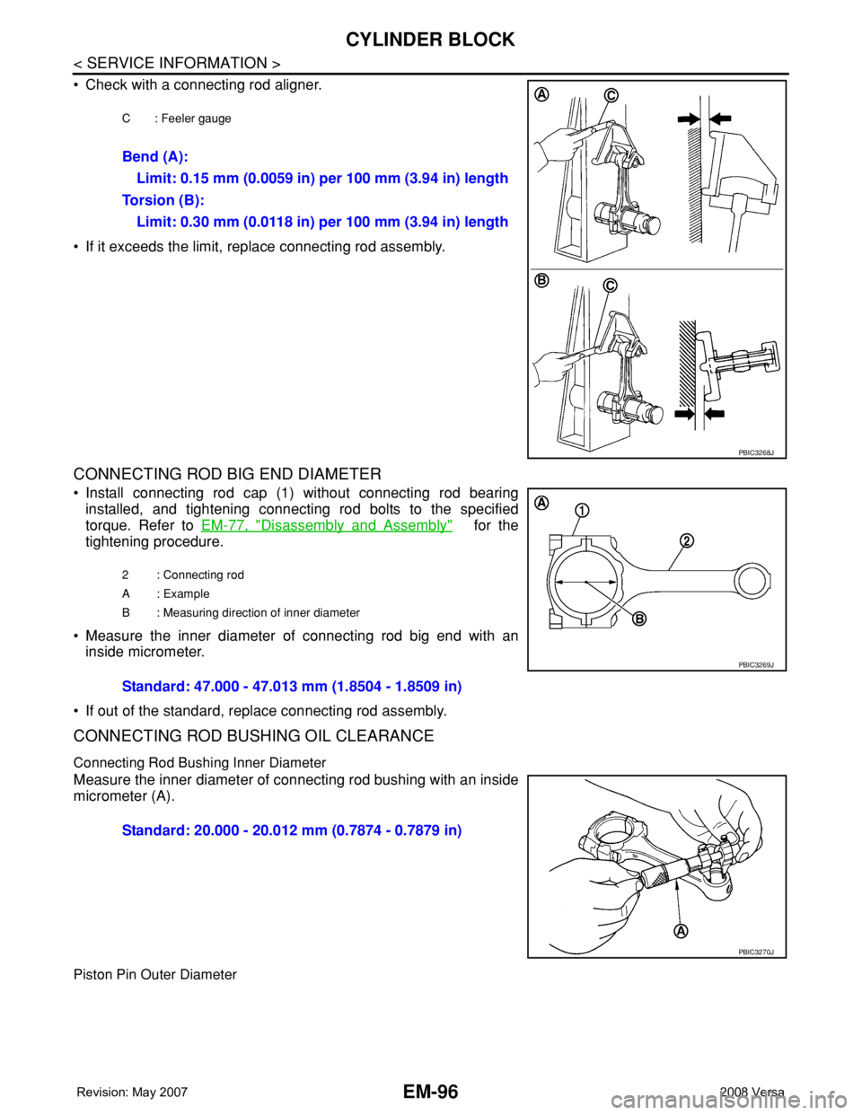
• Check with a connecting rod aligner.
• If it exceeds the limit, replace connecting rod assembly.
CONNECTING ROD BIG END DIAMETER
• Install connecting rod cap (1) without connecting rod bearing
installed, and tightening connecting rod bolts to the specified
torque. Refer to EM-77, "
Disassembly and Assembly" for the
tightening procedure.
• Measure the inner diameter of connecting rod big end with an
inside micrometer.
• If out of the standard, replace connecting rod assembly.
CONNECTING ROD BUSHING OIL CLEARANCE
Connecting Rod Bushing Inner Diameter
Measure the inner diameter of connecting rod bushing with an inside
micrometer (A).
Piston Pin Outer Diameter
C : Feeler gauge
Bend (A):
Limit: 0.15 mm (0.0059 in) per 100 mm (3.94 in) length
To r s i o n ( B ) :
Limit: 0.30 mm (0.0118 in) per 100 mm (3.94 in) length
PBIC3268J
2 : Connecting rod
A : Example
B : Measuring direction of inner diameter
Standard: 47.000 - 47.013 mm (1.8504 - 1.8509 in)
PBIC3269J
Standard: 20.000 - 20.012 mm (0.7874 - 0.7879 in)
PBIC3270J
Page 1774 of 2771
CYLINDER BLOCK
EM-97
< SERVICE INFORMATION >
C
D
E
F
G
H
I
J
K
L
MA
EM
N
P O
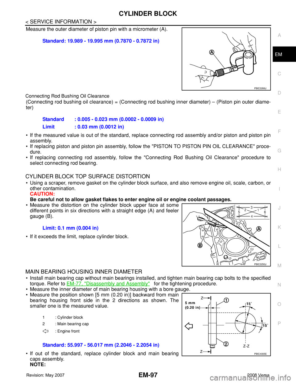
Measure the outer diameter of piston pin with a micrometer (A).
Connecting Rod Bushing Oil Clearance
(Connecting rod bushing oil clearance) = (Connecting rod bushing inner diameter) – (Piston pin outer diame-
ter)
• If the measured value is out of the standard, replace connecting rod assembly and/or piston and piston pin
assembly.
• If replacing piston and piston pin assembly, follow the "PISTON TO PISTON PIN OIL CLEARANCE" proce-
dure.
• If replacing connecting rod assembly, follow the "Connecting Rod Bushing Oil Clearance" procedure to
select connecting rod bearing.
CYLINDER BLOCK TOP SURFACE DISTORTION
• Using a scraper, remove gasket on the cylinder block surface, and also remove engine oil, scale, carbon, or
other contamination.
CAUTION:
Be careful not to allow gasket flakes to enter engine oil or engine coolant passages.
• Measure the distortion on the cylinder block upper face at some
different points in six directions with a straight edge (A) and feeler
gauge (B).
• If it exceeds the limit, replace cylinder block.
MAIN BEARING HOUSING INNER DIAMETER
• Install main bearing cap without main bearings installed, and tighten main bearing cap bolts to the specified
torque. Refer to EM-77, "
Disassembly and Assembly" for the tightening procedure.
• Measure the inner diameter of main bearing housing with a bore gauge.
• Measure the position shown [5 mm (0.20 in)] backward from main
bearing housing front side in the 2 directions as shown. The
smaller one is the measured value.
• If out of the standard, replace cylinder block and main bearing
caps assembly.
NOTE:Standard: 19.989 - 19.995 mm (0.7870 - 0.7872 in)
PBIC3266J
Standard : 0.005 - 0.023 mm (0.0002 - 0.0009 in)
Limit : 0.03 mm (0.0012 in)
Limit: 0.1 mm (0.004 in)
PBIC3250J
1 : Cylinder block
2 : Main bearing cap
: Engine front
Standard: 55.997 - 56.017 mm (2.2046 - 2.2054 in)
PBIC4005E
Page 1777 of 2771
EM-100
< SERVICE INFORMATION >
CYLINDER BLOCK
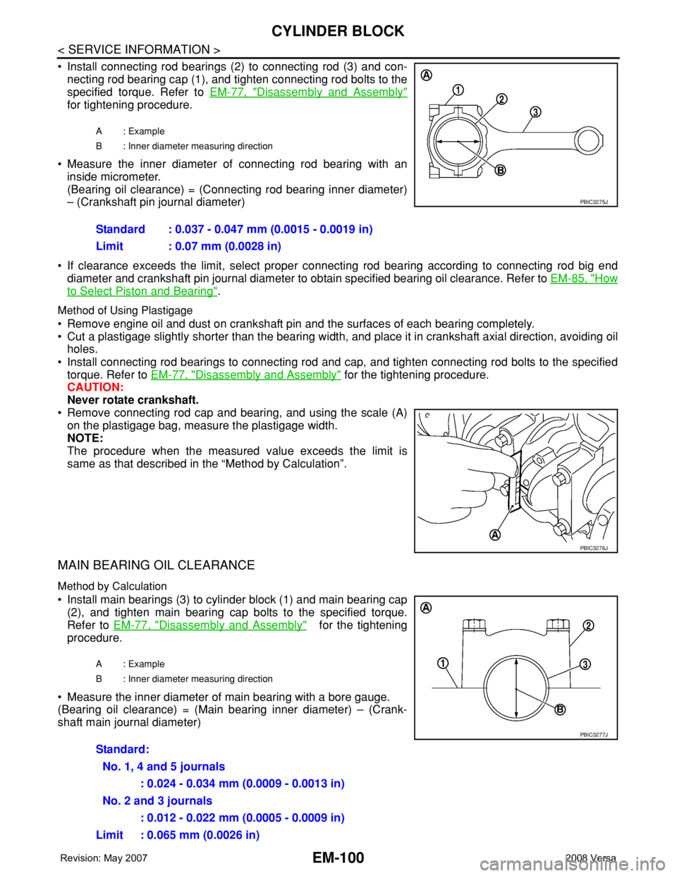
• Install connecting rod bearings (2) to connecting rod (3) and con-
necting rod bearing cap (1), and tighten connecting rod bolts to the
specified torque. Refer to EM-77, "
Disassembly and Assembly"
for tightening procedure.
• Measure the inner diameter of connecting rod bearing with an
inside micrometer.
(Bearing oil clearance) = (Connecting rod bearing inner diameter)
– (Crankshaft pin journal diameter)
• If clearance exceeds the limit, select proper connecting rod bearing according to connecting rod big end
diameter and crankshaft pin journal diameter to obtain specified bearing oil clearance. Refer to EM-85, "
How
to Select Piston and Bearing".
Method of Using Plastigage
• Remove engine oil and dust on crankshaft pin and the surfaces of each bearing completely.
• Cut a plastigage slightly shorter than the bearing width, and place it in crankshaft axial direction, avoiding oil
holes.
• Install connecting rod bearings to connecting rod and cap, and tighten connecting rod bolts to the specified
torque. Refer to EM-77, "
Disassembly and Assembly" for the tightening procedure.
CAUTION:
Never rotate crankshaft.
• Remove connecting rod cap and bearing, and using the scale (A)
on the plastigage bag, measure the plastigage width.
NOTE:
The procedure when the measured value exceeds the limit is
same as that described in the “Method by Calculation”.
MAIN BEARING OIL CLEARANCE
Method by Calculation
• Install main bearings (3) to cylinder block (1) and main bearing cap
(2), and tighten main bearing cap bolts to the specified torque.
Refer to EM-77, "
Disassembly and Assembly" for the tightening
procedure.
• Measure the inner diameter of main bearing with a bore gauge.
(Bearing oil clearance) = (Main bearing inner diameter) – (Crank-
shaft main journal diameter)
A : Example
B : Inner diameter measuring direction
Standard : 0.037 - 0.047 mm (0.0015 - 0.0019 in)
Limit : 0.07 mm (0.0028 in)
PBIC3275J
PBIC3276J
A : Example
B : Inner diameter measuring direction
Standard:
No. 1, 4 and 5 journals
: 0.024 - 0.034 mm (0.0009 - 0.0013 in)
No. 2 and 3 journals
: 0.012 - 0.022 mm (0.0005 - 0.0009 in)
Limit : 0.065 mm (0.0026 in)
PBIC3277J
Page 1778 of 2771
CYLINDER BLOCK
EM-101
< SERVICE INFORMATION >
C
D
E
F
G
H
I
J
K
L
MA
EM
N
P O
• If clearance exceeds the limit, select proper main bearing according to main bearing inner diameter and
crankshaft main journal diameter to obtain specified bearing oil clearance. Refer to EM-85, "
How to Select
Piston and Bearing".
Method of Using Plastigage
• Remove engine oil and dust on crankshaft main journal and the surfaces of each bearing completely.
• Cut a plastigage slightly shorter than the bearing width, and place it in crankshaft axial direction, avoiding oil
holes.
• Install main bearings to cylinder block and main bearing cap, and tighten main bearing cap bolts to the spec-
ified torque. Refer to EM-77, "
Disassembly and Assembly" for the tightening procedure.
CAUTION:
Never rotate crankshaft.
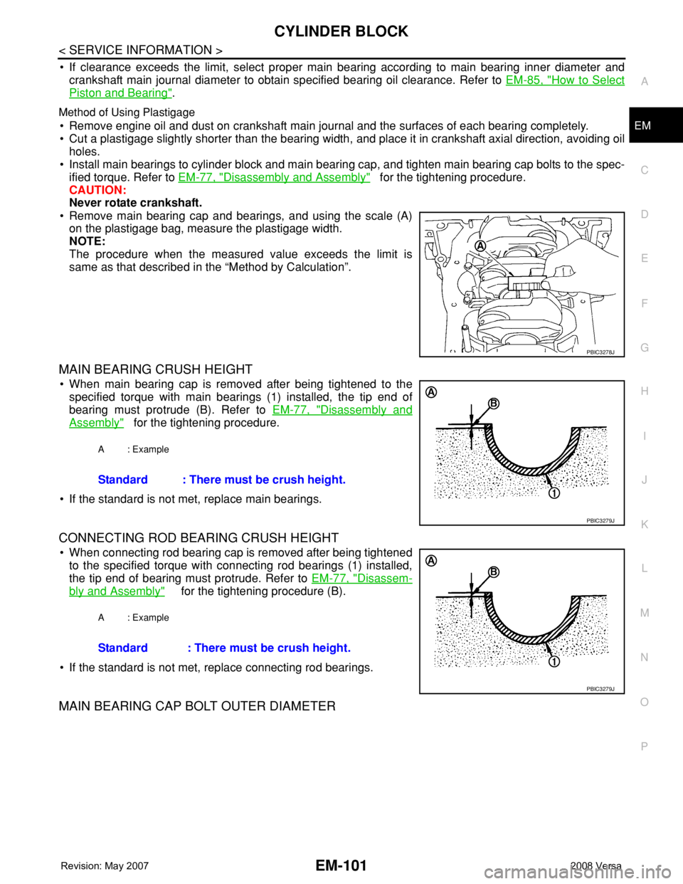
• Remove main bearing cap and bearings, and using the scale (A)
on the plastigage bag, measure the plastigage width.
NOTE:
The procedure when the measured value exceeds the limit is
same as that described in the “Method by Calculation”.
MAIN BEARING CRUSH HEIGHT
• When main bearing cap is removed after being tightened to the
specified torque with main bearings (1) installed, the tip end of
bearing must protrude (B). Refer to EM-77, "
Disassembly and
Assembly" for the tightening procedure.
• If the standard is not met, replace main bearings.
CONNECTING ROD BEARING CRUSH HEIGHT
• When connecting rod bearing cap is removed after being tightened
to the specified torque with connecting rod bearings (1) installed,
the tip end of bearing must protrude. Refer to EM-77, "
Disassem-
bly and Assembly" for the tightening procedure (B).
• If the standard is not met, replace connecting rod bearings.
MAIN BEARING CAP BOLT OUTER DIAMETER
PBIC3278J
A : Example
Standard : There must be crush height.
PBIC3279J
A : Example
Standard : There must be crush height.
PBIC3279J
Page 1780 of 2771
CYLINDER BLOCK
EM-103
< SERVICE INFORMATION >
C
D
E
F
G
H
I
J
K
L
MA
EM
N
P O
• If measured value is out of the standard, replace flywheel.
Movement Amount in Radial (Rotation) Direction
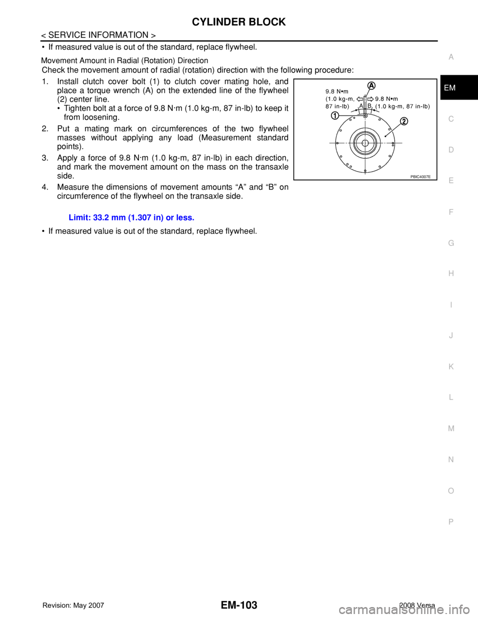
Check the movement amount of radial (rotation) direction with the following procedure:
1. Install clutch cover bolt (1) to clutch cover mating hole, and
place a torque wrench (A) on the extended line of the flywheel
(2) center line.
• Tighten bolt at a force of 9.8 N·m (1.0 kg-m, 87 in-lb) to keep it
from loosening.
2. Put a mating mark on circumferences of the two flywheel
masses without applying any load (Measurement standard
points).
3. Apply a force of 9.8 N·m (1.0 kg-m, 87 in-lb) in each direction,
and mark the movement amount on the mass on the transaxle
side.
4. Measure the dimensions of movement amounts “A” and “B” on
circumference of the flywheel on the transaxle side.
• If measured value is out of the standard, replace flywheel.Limit: 33.2 mm (1.307 in) or less.
PBIC4007E
Page 1796 of 2771
EXHAUST SYSTEM
EX-5
< SERVICE INFORMATION >
C
D
E
F
G
H
I
J
K
L
MA
EX
N
P O
• Be sure to use genuine NISSAN exhaust system parts or equivalents which are specially designed
for heat resistance, corrosion resistance and shape.
• Perform the operation with the exhaust system fully cooled down because the system will be hot
just after the engine stops.
• Be careful not to cut your hand on heat insulator edge.
1. Disconnect harness connector of heated oxygen sensor 2.
• Using Tool, remove heated oxygen sensor 2.
CAUTION:
Be careful not to damage heated oxygen sensor 2.
a.2. Disconnect each joint and mounting rubber.
INSTALLATION
Installation is in the reverse order of removal.
CAUTION:
• Always replace exhaust gaskets and seal bearings with new ones when installing.
• Discard any heated oxygen sensor 2 which has been dropped from a height of more than 0.5 m (19.7
in) onto a hard surface such as a concrete floor; use a new one.
• Before installing a new heated oxygen sensor 2, clean exhaust system threads using the heated oxy-
gen sensor thread cleaner and apply anti-seize lubricant (commercial service tool).
• Do not over tighten heated oxygen sensor 2. Doing so may cause damage to the heated oxygen sen-
sor 2, resulting in the “MIL” coming on.
• Remove deposits from the sealing surface of each connection. Connect them securely to avoid
exhaust leakage.
• Temporarily tighten nuts on the exhaust manifold side and bolts on the vehicle side. Check each part
for unusual interference, and then tighten them to the specified torque.
• When installing each mounting rubber, avoid twisting or unusual extension in up/down and right/left
directions.
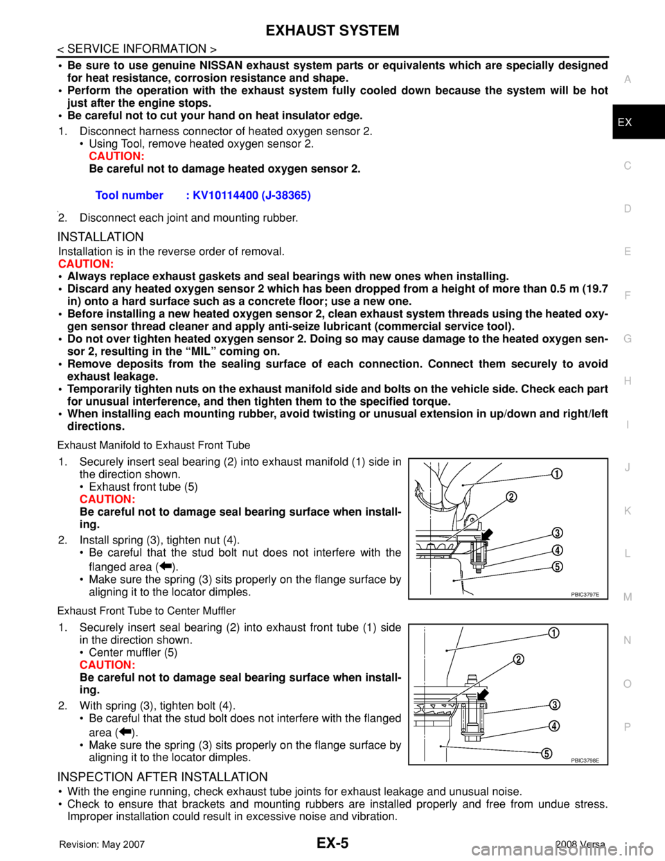
Exhaust Manifold to Exhaust Front Tube
1. Securely insert seal bearing (2) into exhaust manifold (1) side in
the direction shown.
• Exhaust front tube (5)
CAUTION:
Be careful not to damage seal bearing surface when install-
ing.
2. Install spring (3), tighten nut (4).
• Be careful that the stud bolt nut does not interfere with the
flanged area ( ).
• Make sure the spring (3) sits properly on the flange surface by
aligning it to the locator dimples.
Exhaust Front Tube to Center Muffler
1. Securely insert seal bearing (2) into exhaust front tube (1) side
in the direction shown.
• Center muffler (5)
CAUTION:
Be careful not to damage seal bearing surface when install-
ing.
2. With spring (3), tighten bolt (4).
• Be careful that the stud bolt does not interfere with the flanged
area ( ).
• Make sure the spring (3) sits properly on the flange surface by
aligning it to the locator dimples.
INSPECTION AFTER INSTALLATION
• With the engine running, check exhaust tube joints for exhaust leakage and unusual noise.
• Check to ensure that brackets and mounting rubbers are installed properly and free from undue stress.
Improper installation could result in excessive noise and vibration.Tool number : KV10114400 (J-38365)
PBIC3797E
PBIC3798E