2008 NISSAN LATIO torque
[x] Cancel search: torquePage 769 of 2771
![NISSAN LATIO 2008 Service Repair Manual BRC-4
< SERVICE INFORMATION >[ABS]
PREPARATION
PREPARATION
Special Service ToolINFOID:0000000001703823
The actual shapes of Kent-Moore tools may differ from those of special service tools illustrated NISSAN LATIO 2008 Service Repair Manual BRC-4
< SERVICE INFORMATION >[ABS]
PREPARATION
PREPARATION
Special Service ToolINFOID:0000000001703823
The actual shapes of Kent-Moore tools may differ from those of special service tools illustrated](/manual-img/5/57360/w960_57360-768.png)
BRC-4
< SERVICE INFORMATION >[ABS]
PREPARATION
PREPARATION
Special Service ToolINFOID:0000000001703823
The actual shapes of Kent-Moore tools may differ from those of special service tools illustrated here.
Commercial Service ToolINFOID:0000000001703824
Tool number
(Kent-Moore No.)
Tool nameDescription
KV991J0080
(J-45741)
ABS active wheel sensor testerChecking operation of ABS active wheel sen-
sors
WFIA0101E
Tool nameDescription
1. Flare nut crowfoot
2. Torque wrenchRemoving and installing brake piping
a: 10 mm (0.39 in)/12 mm (0.47 in)
S-NT360
Page 782 of 2771
![NISSAN LATIO 2008 Service Repair Manual TROUBLE DIAGNOSIS
BRC-17
< SERVICE INFORMATION >[ABS]
C
D
E
G
H
I
J
K
L
MA
B
BRC
N
O
P
• If ABS actuator and electric unit (control unit) connection is loose, tighten the piping to the specified
tor NISSAN LATIO 2008 Service Repair Manual TROUBLE DIAGNOSIS
BRC-17
< SERVICE INFORMATION >[ABS]
C
D
E
G
H
I
J
K
L
MA
B
BRC
N
O
P
• If ABS actuator and electric unit (control unit) connection is loose, tighten the piping to the specified
tor](/manual-img/5/57360/w960_57360-781.png)
TROUBLE DIAGNOSIS
BRC-17
< SERVICE INFORMATION >[ABS]
C
D
E
G
H
I
J
K
L
MA
B
BRC
N
O
P
• If ABS actuator and electric unit (control unit) connection is loose, tighten the piping to the specified
torque and recheck for leaks.
• If there is damage to the connection flare nut or ABS actuator and electric unit (control unit) threads,
replace the damaged part and recheck for leaks.
• When there is fluid leaking or seeping from a fluid connection, use a clean cloth to wipe off the fluid and
recheck for leaks. If fluid is still seeping out, replace the damaged part. If the fluid is leaking at the ABS
actuator and electric unit (control unit), replace the ABS actuator and electric unit (control unit) assem-
bly.
CAUTION:
The ABS actuator and electric unit (control unit) cannot be disassembled and must be replaced
as an assembly.
3. Check the brake pads for excessive wear.
POWER SYSTEM TERMINAL LOOSENESS AND BATTERY INSPECTION
Make sure the battery positive cable, negative cable and ground connection are not loose. In addition, make
sure the battery is sufficiently charged.
ABS WARNING LAMP INSPECTION
1. Make sure ABS warning lamp turns on for approximately 2 seconds when the ignition switch is turned ON.
If it does not, check CAN communications. If there are no errors with the CAN communication system,
replace the combination meter. Refer to IP-11, "
Removal and Installation".
2. Make sure the lamp turns off approximately 2 seconds after the ignition switch is turned ON. If the lamp
does not turn off, conduct self-diagnosis of ABS actuator and electric unit (control unit). If no malfunctions
are detected in self-diagnosis, replace combination meter. Refer to IP-11, "
Removal and Installation".
3. After conducting the self-diagnosis, be sure to erase the error memory. Refer to BRC-18, "
CONSULT-III
Function (ABS)".
Warning Lamp and Indicator TimingINFOID:0000000001703836
Note 1: Brake warning lamp will turn on when the parking brake is applied or when the brake fluid level is low.
x: ON
–: OFF
Control Unit Input/Output Signal StandardINFOID:0000000001703837
REFERENCE VALUE FROM CONSULT-III
CAUTION:
The display shows the control unit calculation data, so a normal value might be displayed even in the
event the output circuit (harness) is open or short circuited.
ConditionABS
warning lampBRAKE
warning lamp
[Note 1]Remarks
When the ignition switch is OFF – – –
After the ignition switch is turned ON for approx. 1
second××–
After the ignition switch is turned ON for approx. 2
seconds––Lamp goes off approx. 2 seconds after the
engine is started.
ABS malfunction×––
EBD malfunction××–
Page 797 of 2771
![NISSAN LATIO 2008 Service Repair Manual BRC-32
< SERVICE INFORMATION >[ABS]
WHEEL SENSORS
WHEEL SENSORS
Removal and InstallationINFOID:0000000001703850
NOTE:
The top portion of the figure (front side) shows view from LH side of vehicle. RH NISSAN LATIO 2008 Service Repair Manual BRC-32
< SERVICE INFORMATION >[ABS]
WHEEL SENSORS
WHEEL SENSORS
Removal and InstallationINFOID:0000000001703850
NOTE:
The top portion of the figure (front side) shows view from LH side of vehicle. RH](/manual-img/5/57360/w960_57360-796.png)
BRC-32
< SERVICE INFORMATION >[ABS]
WHEEL SENSORS
WHEEL SENSORS
Removal and InstallationINFOID:0000000001703850
NOTE:
The top portion of the figure (front side) shows view from LH side of vehicle. RH side is the mirror image.
REMOVAL
Pay attention to the following when removing wheel sensor.
CAUTION:
• As much as possible, avoid rotating wheel sensor when removing it. Pull wheel sensors out without
pulling on sensor harness.
• Take care to avoid damaging wheel sensor edges or rotor teeth. Remove wheel sensor first before
removing front or rear wheel hub. This is to avoid damage to wheel sensor wiring and loss of sensor
function.
INSTALLATION
Pay attention to the following when installing wheel sensor. Tighten installation bolts and nuts to the specified
torques.
• When installing, make sure there is no foreign material such as iron chips on and in the mounting hole of the
wheel sensor. Make sure no foreign material has been caught in the sensor rotor. Remove any foreign mate-
rial and clean the mount.
• When installing front wheel sensor, press rubber grommets of strut bracket and body all the way in until they
get locked, and be careful not to apply a twist to harness. Harness should not be twisted after installation.
(Install it with harness paint mark on body side grommet facing front of vehicle, and the strut side grommet
facing outside of vehicle.)
A. Front B. Rear 1. Front wheel sensor connector (LH)
2. Front wheel sensor (LH) 3. Rear wheel sensor (LH) 4. Rear wheel sensor connector (LH)
5. Rear wheel sensor connector (RH) 6. Rear wheel sensor (RH) 7. Side member
8. Left 9. Right : Front
Refer to GI section for symbol marks in the figure.
SFIA3090E
Page 800 of 2771
![NISSAN LATIO 2008 Service Repair Manual ACTUATOR AND ELECTRIC UNIT (ASSEMBLY)
BRC-35
< SERVICE INFORMATION >[ABS]
C
D
E
G
H
I
J
K
L
MA
B
BRC
N
O
P
ACTUATOR AND ELECTRIC UNIT (ASSEMBLY)
Removal and InstallationINFOID:0000000001703852
CAUTION NISSAN LATIO 2008 Service Repair Manual ACTUATOR AND ELECTRIC UNIT (ASSEMBLY)
BRC-35
< SERVICE INFORMATION >[ABS]
C
D
E
G
H
I
J
K
L
MA
B
BRC
N
O
P
ACTUATOR AND ELECTRIC UNIT (ASSEMBLY)
Removal and InstallationINFOID:0000000001703852
CAUTION](/manual-img/5/57360/w960_57360-799.png)
ACTUATOR AND ELECTRIC UNIT (ASSEMBLY)
BRC-35
< SERVICE INFORMATION >[ABS]
C
D
E
G
H
I
J
K
L
MA
B
BRC
N
O
P
ACTUATOR AND ELECTRIC UNIT (ASSEMBLY)
Removal and InstallationINFOID:0000000001703852
CAUTION:
• Before servicing, disconnect battery cables.
• To remove brake tube, use flare nut wrench to prevent flare nuts and brake tube from being dam-
aged. To install, use flare nut torque wrench, tighten flare nut to the specified torque. Refer to BR-10,
"Hydraulic Circuit" .
• Do not apply excessive impact to ABS actuator and electric unit (control unit), such as dropping it.
• Do not remove and install actuator by holding harness.
• After work is completed, bleed air from brake tube and hose. Refer to BR-8, "
Bleeding Brake Sys-
tem" .
REMOVAL
1. Disconnect ABS actuator and electric unit (control unit) connector.
2. Loosen brake tube flare nuts, then remove brake tubes from ABS actuator and electric unit (control unit).
3. Remove brake booster hose from engine. Refer to BR-21, "
Removal and Installation" .
4. Remove ABS actuator and electric unit (control unit) bracket mounting bolts.
5. Remove ABS actuator and electric unit (control unit) from vehicle.
INSTALLATION
1. To front right 2. To rear left 3. To rear right
4. To front left 5. From master cylinder primary side 6. From master cylinder secondary
side
7. ABS actuator and electric unit (con-
trol unit)8. Harness connector : Front
Refer to GI section for symbol marks in the figure.
WFIA0506E
Page 841 of 2771

CVT-2
Description ..............................................................60
CONSULT-III Reference Value in Data Monitor
Mode .......................................................................
60
On Board Diagnosis Logic ......................................60
Possible Cause .......................................................60
DTC Confirmation Procedure .................................60
Wiring Diagram - CVT - STSIG ...............................61
Diagnosis Procedure ..............................................62
DTC P0703 STOP LAMP SWITCH CIRCUIT ....63
Description ..............................................................63
CONSULT-III Reference Value in Data Monitor
Mode .......................................................................
63
On Board Diagnosis Logic ......................................63
Possible Cause .......................................................63
DTC Confirmation Procedure .................................63
Diagnosis Procedure ..............................................63
DTC P0705 PARK/NEUTRAL POSITION
SWITCH .............................................................
65
Description ..............................................................65
CONSULT-III Reference Value in Data Monitor
Mode .......................................................................
65
On Board Diagnosis Logic ......................................65
Possible Cause .......................................................65
DTC Confirmation Procedure .................................65
Wiring Diagram - CVT - PNP/SW ...........................67
Diagnosis Procedure ..............................................68
Component Inspection ............................................70
DTC P0710 CVT FLUID TEMPERATURE
SENSOR CIRCUIT .............................................
71
Description ..............................................................71
CONSULT-III Reference Value in Data Monitor
Mode .......................................................................
71
On Board Diagnosis Logic ......................................71
Possible Cause .......................................................71
DTC Confirmation Procedure .................................71
Wiring Diagram - CVT - FTS ...................................72
Diagnosis Procedure ..............................................73
Component Inspection ............................................74
DTC P0715 INPUT SPEED SENSOR CIR-
CUIT (PRI SPEED SENSOR) ............................
76
Description ..............................................................76
CONSULT-III Reference Value in Data Monitor
Mode .......................................................................
76
On Board Diagnosis Logic ......................................76
Possible Cause .......................................................76
DTC Confirmation Procedure .................................76
Wiring Diagram - CVT - PRSCVT ...........................77
Diagnosis Procedure ..............................................78
DTC P0720 VEHICLE SPEED SENSOR CVT
(SECONDARY SPEED SENSOR) .....................
80
Description ..............................................................80
CONSULT-III Reference Value in Data Monitor
Mode .......................................................................
80
On Board Diagnosis Logic ......................................80
Possible Cause .......................................................80
DTC Confirmation Procedure ..................................80
Wiring Diagram - CVT - SESCVT ...........................81
Diagnosis Procedure ...............................................82
DTC P0725 ENGINE SPEED SIGNAL ..............85
Description ..............................................................85
CONSULT-III Reference Value in Data Monitor
Mode .......................................................................
85
On Board Diagnosis Logic ......................................85
Possible Cause .......................................................85
DTC Confirmation Procedure ..................................85
Diagnosis Procedure ...............................................85
DTC P0730 BELT DAMAGE .............................87
Description ..............................................................87
CONSULT-III Reference Value in Data Monitor
Mode .......................................................................
87
On Board Diagnosis Logic ......................................87
Possible Cause .......................................................87
DTC Confirmation Procedure ..................................87
Diagnosis Procedure ...............................................87
DTC P0740 TORQUE CONVERTER CLUTCH
SOLENOID VALVE ...........................................
88
Description ..............................................................88
CONSULT-III Reference Value in Data Monitor
Mode .......................................................................
88
On Board Diagnosis Logic ......................................88
Possible Cause .......................................................88
DTC Confirmation Procedure ..................................88
Wiring Diagram - CVT - TCV ..................................89
Diagnosis Procedure ...............................................90
Component Inspection ............................................91
DTC P0744 A/T TCC S/V FUNCTION (LOCK-
UP) .....................................................................
93
Description ..............................................................93
CONSULT-III Reference Value in Data Monitor
Mode .......................................................................
93
On Board Diagnosis Logic ......................................93
Possible Cause .......................................................93
DTC Confirmation Procedure ..................................93
Diagnosis Procedure ...............................................93
DTC P0745 LINE PRESSURE SOLENOID
VALVE ...............................................................
95
Description ..............................................................95
CONSULT-III Reference Value in Data Monitor
Mode .......................................................................
95
On Board Diagnosis Logic ......................................95
Possible Cause .......................................................95
DTC Confirmation Procedure ..................................95
Wiring Diagram - CVT - LPSV ................................96
Diagnosis Procedure ...............................................97
Component Inspection ............................................98
DTC P0746 PRESSURE CONTROL SOLE-
NOID A PERFORMANCE (LINE PRESSURE
SOLENOID VALVE) .........................................
100
Description ............................................................100
Page 857 of 2771

CVT-18
< SERVICE INFORMATION >
CVT SYSTEM
CVT SYSTEM
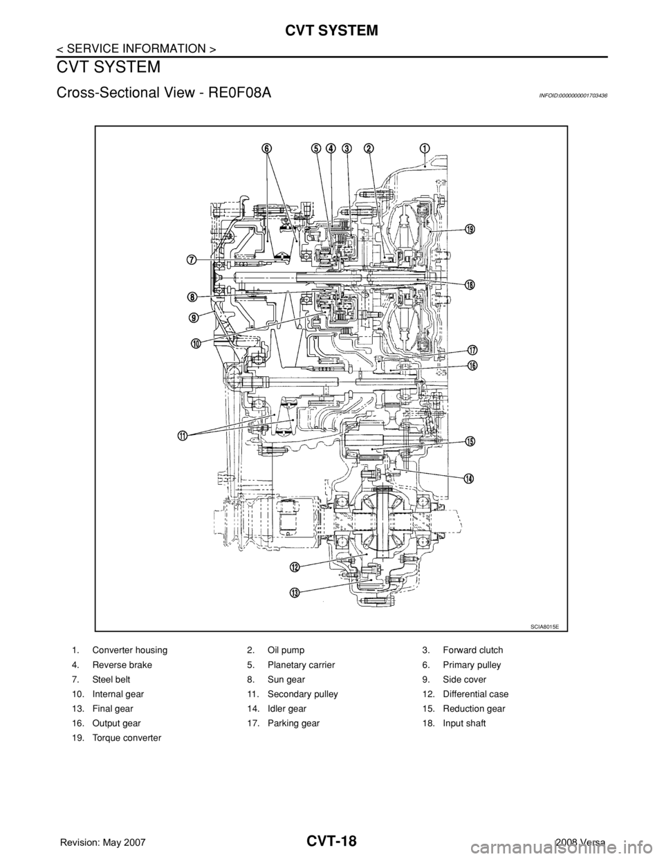
Cross-Sectional View - RE0F08AINFOID:0000000001703436
1. Converter housing 2. Oil pump 3. Forward clutch
4. Reverse brake 5. Planetary carrier 6. Primary pulley
7. Steel belt 8. Sun gear 9. Side cover
10. Internal gear 11. Secondary pulley 12. Differential case
13. Final gear 14. Idler gear 15. Reduction gear
16. Output gear 17. Parking gear 18. Input shaft
19. Torque converter
SCIA8015E
Page 859 of 2771

CVT-20
< SERVICE INFORMATION >
CVT SYSTEM
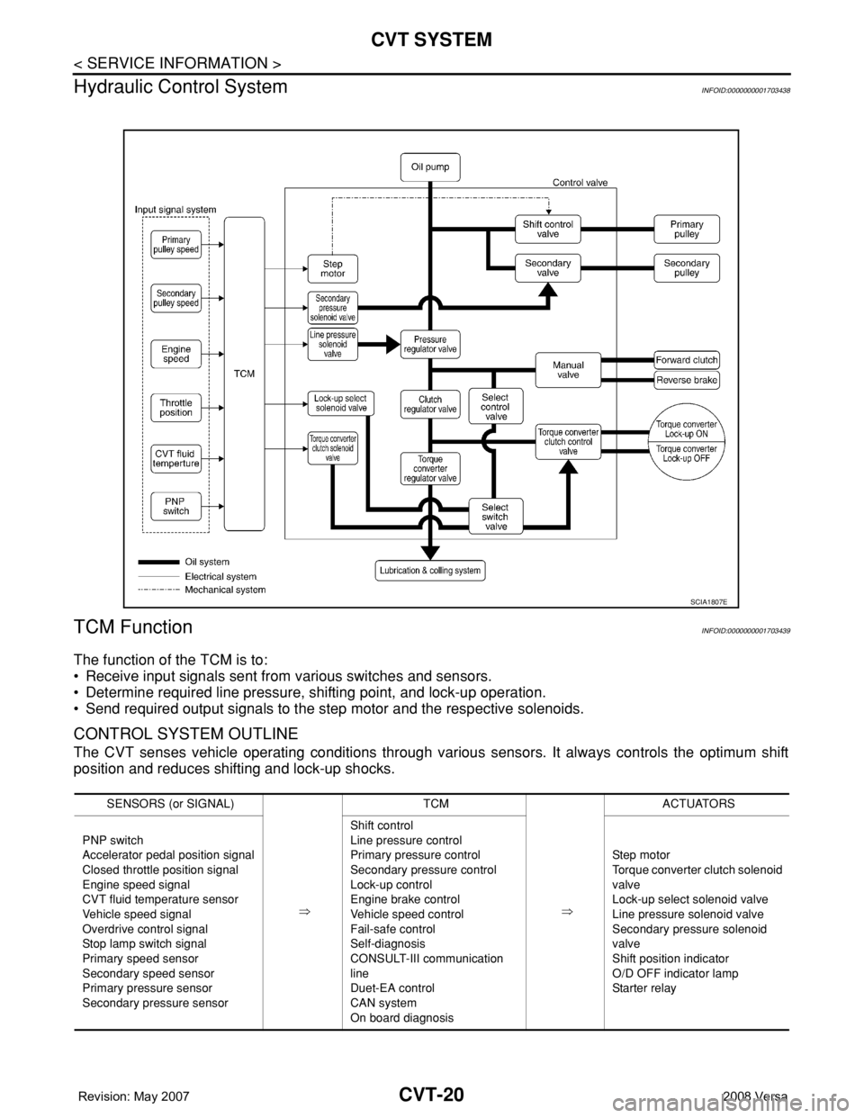
Hydraulic Control System
INFOID:0000000001703438
TCM FunctionINFOID:0000000001703439
The function of the TCM is to:
• Receive input signals sent from various switches and sensors.
• Determine required line pressure, shifting point, and lock-up operation.
• Send required output signals to the step motor and the respective solenoids.
CONTROL SYSTEM OUTLINE
The CVT senses vehicle operating conditions through various sensors. It always controls the optimum shift
position and reduces shifting and lock-up shocks.
SCIA1807E
SENSORS (or SIGNAL)
⇒TCM
⇒ACTUATORS
PNP switch
Accelerator pedal position signal
Closed throttle position signal
Engine speed signal
CVT fluid temperature sensor
Vehicle speed signal
Overdrive control signal
Stop lamp switch signal
Primary speed sensor
Secondary speed sensor
Primary pressure sensor
Secondary pressure sensorShift control
Line pressure control
Primary pressure control
Secondary pressure control
Lock-up control
Engine brake control
Vehicle speed control
Fail-safe control
Self-diagnosis
CONSULT-III communication
line
Duet-EA control
CAN system
On board diagnosisSte p m ot or
Torque converter clutch solenoid
valve
Lock-up select solenoid valve
Line pressure solenoid valve
Secondary pressure solenoid
valve
Shift position indicator
O/D OFF indicator lamp
Starter relay
Page 861 of 2771

CVT-22
< SERVICE INFORMATION >
CVT SYSTEM
Input/Output Signal of TCM
INFOID:0000000001703441
*1: Input by CAN communications.
*2: Output by CAN communications.
*3: If these input and output signals are different, the TCM triggers the fail-safe function.
Line Pressure and Secondary Pressure ControlINFOID:0000000001703442
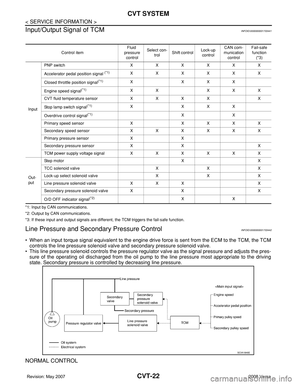
• When an input torque signal equivalent to the engine drive force is sent from the ECM to the TCM, the TCM
controls the line pressure solenoid valve and secondary pressure solenoid valve.
• This line pressure solenoid controls the pressure regulator valve as the signal pressure and adjusts the pres-
sure of the operating oil discharged from the oil pump to the line pressure most appropriate to the driving
state. Secondary pressure is controlled by decreasing line pressure.
NORMAL CONTROL
Control itemFluid
pressure
controlSelect con-
trolShift controlLock-up
controlCAN com-
munication
controlFail-safe
function
(*3)
InputPNP switch XXXXXX
Accelerator pedal position signal
(*1)XXXXXX
Closed throttle position signal
(*1)X XXX
Engine speed signal
(*1)XX XXX
CVT fluid temperature sensor X X X X X
Stop lamp switch signal
(*1)X XXX
Overdrive control signal
(*1)XX
Primary speed sensor X X X X X
Secondary speed sensor X X X X X X
Primary pressure sensor X X
Secondary pressure sensor X X X
TCM power supply voltage signal X X X X X X
Out-
putStep motor X X
TCC solenoid valve X X X
Lock-up select solenoid valve X X X
Line pressure solenoid valve X X X X
Secondary pressure solenoid valve X X X
O/D OFF indicator signal
(*2)XX
SCIA1846E