Page 332 of 2771

AT-320
< SERVICE INFORMATION >
ASSEMBLY
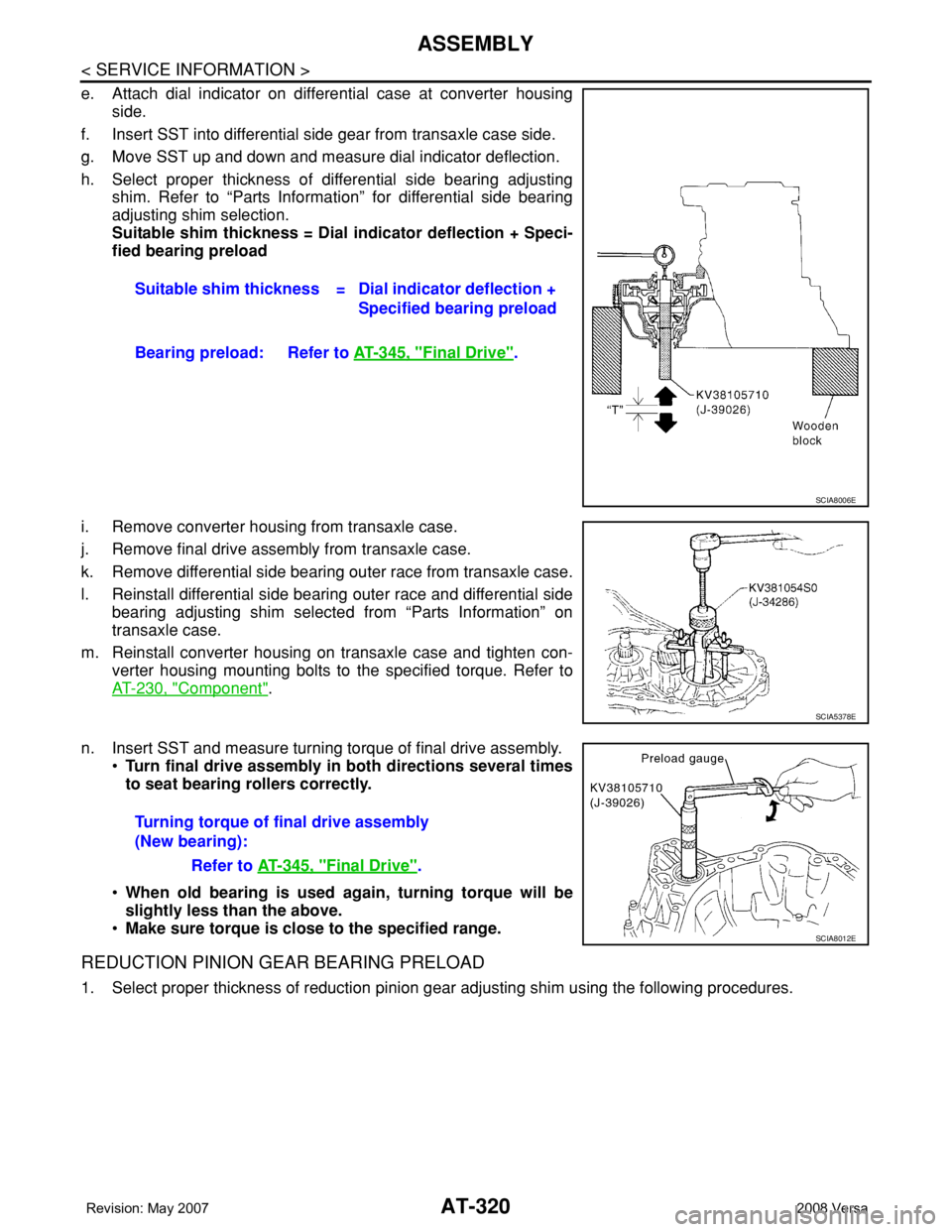
e. Attach dial indicator on differential case at converter housing
side.
f. Insert SST into differential side gear from transaxle case side.
g. Move SST up and down and measure dial indicator deflection.
h. Select proper thickness of differential side bearing adjusting
shim. Refer to “Parts Information” for differential side bearing
adjusting shim selection.
Suitable shim thickness = Dial indicator deflection + Speci-
fied bearing preload
i. Remove converter housing from transaxle case.
j. Remove final drive assembly from transaxle case.
k. Remove differential side bearing outer race from transaxle case.
l. Reinstall differential side bearing outer race and differential side
bearing adjusting shim selected from “Parts Information” on
transaxle case.
m. Reinstall converter housing on transaxle case and tighten con-
verter housing mounting bolts to the specified torque. Refer to
AT-230, "
Component".
n. Insert SST and measure turning torque of final drive assembly.
•Turn final drive assembly in both directions several times
to seat bearing rollers correctly.
•When old bearing is used again, turning torque will be
slightly less than the above.
•Make sure torque is close to the specified range.
REDUCTION PINION GEAR BEARING PRELOAD
1. Select proper thickness of reduction pinion gear adjusting shim using the following procedures.Suitable shim thickness = Dial indicator deflection +
Specified bearing preload
Bearing preload: Refer to AT-345, "
Final Drive".
SCIA8006E
SCIA5378E
Turning torque of final drive assembly
(New bearing):
Refer to AT-345, "
Final Drive".
SCIA8012E
Page 334 of 2771

AT-322
< SERVICE INFORMATION >
ASSEMBLY
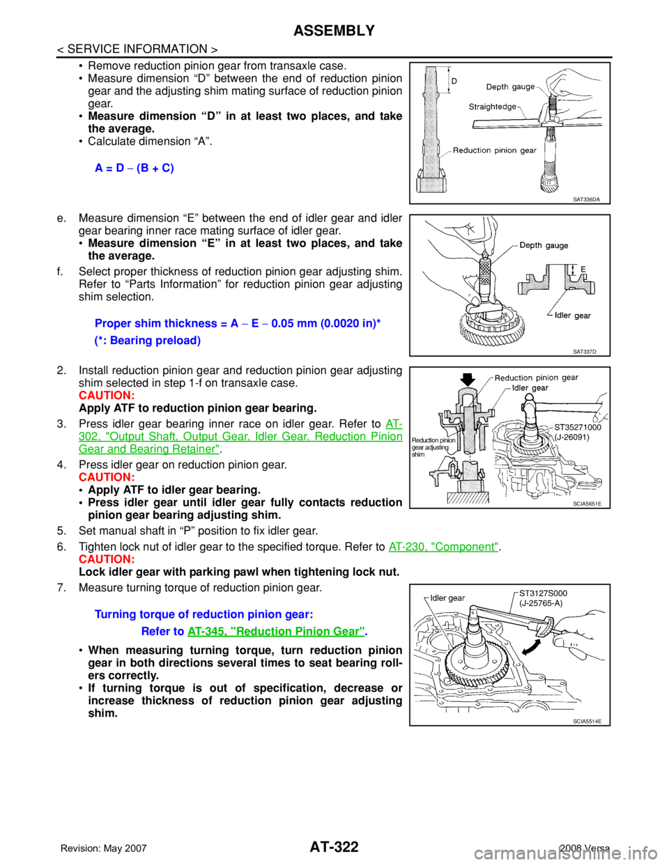
• Remove reduction pinion gear from transaxle case.
• Measure dimension “D” between the end of reduction pinion
gear and the adjusting shim mating surface of reduction pinion
gear.
•Measure dimension “D” in at least two places, and take
the average.
• Calculate dimension “A”.
e. Measure dimension “E” between the end of idler gear and idler
gear bearing inner race mating surface of idler gear.
•Measure dimension “E” in at least two places, and take
the average.
f. Select proper thickness of reduction pinion gear adjusting shim.
Refer to “Parts Information” for reduction pinion gear adjusting
shim selection.
2. Install reduction pinion gear and reduction pinion gear adjusting
shim selected in step 1-f on transaxle case.
CAUTION:
Apply ATF to reduction pinion gear bearing.
3. Press idler gear bearing inner race on idler gear. Refer to AT-
302, "Output Shaft, Output Gear, Idler Gear, Reduction Pinion
Gear and Bearing Retainer".
4. Press idler gear on reduction pinion gear.
CAUTION:
• Apply ATF to idler gear bearing.
• Press idler gear until idler gear fully contacts reduction
pinion gear bearing adjusting shim.
5. Set manual shaft in “P” position to fix idler gear.
6. Tighten lock nut of idler gear to the specified torque. Refer to AT-230, "
Component".
CAUTION:
Lock idler gear with parking pawl when tightening lock nut.
7. Measure turning torque of reduction pinion gear.
•When measuring turning torque, turn reduction pinion
gear in both directions several times to seat bearing roll-
ers correctly.
•If turning torque is out of specification, decrease or
increase thickness of reduction pinion gear adjusting
shim.A = D − (B + C)
SAT336DA
Proper shim thickness = A − E − 0.05 mm (0.0020 in)*
(*: Bearing preload)
SAT337D
Turning torque of reduction pinion gear:
Refer to AT-345, "
Reduction Pinion Gear".
SCIA5651E
SCIA5514E
Page 335 of 2771
ASSEMBLY
AT-323
< SERVICE INFORMATION >
D
E
F
G
H
I
J
K
L
MA
B
AT
N
O
P
8. After properly adjusting turning torque, clinch idler gear lock nut
as shown.
CAUTION:
Do not reuse idler gear lock nut.
OUTPUT SHAFT END PLAY
1. Select proper thickness of output shaft adjusting shim using the
following procedures.
a. Install bearing retainer (1) in transaxle case. Refer to AT-302,
"Output Shaft, Output Gear, Idler Gear, Reduction Pinion Gear
and Bearing Retainer".
b. Install needle bearing on bearing retainer.
CAUTION:
Be careful to direction of needle bearing.
SCIA4915E
SCIA8013E
SCIA5909J
SCIA4917E
Page 337 of 2771

ASSEMBLY
AT-325
< SERVICE INFORMATION >
D
E
F
G
H
I
J
K
L
MA
B
AT
N
O
P
• Completely remove all moisture, oil and old sealant, etc. from the transaxle case and side cover
mounting surfaces.
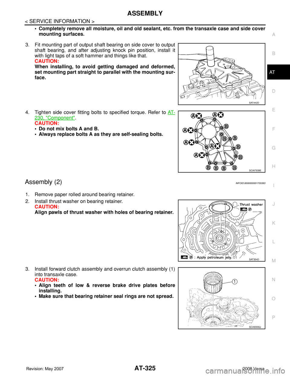
3. Fit mounting part of output shaft bearing on side cover to output
shaft bearing, and after adjusting knock pin position, install it
with light taps of a soft hammer and things like that.
CAUTION:
When installing, to avoid getting damaged and deformed,
set mounting part straight to parallel with the mounting sur-
face.
4. Tighten side cover fitting bolts to specified torque. Refer to AT-
230, "Component".
CAUTION:
• Do not mix bolts A and B.
• Always replace bolts A as they are self-sealing bolts.
Assembly (2)INFOID:0000000001703393
1. Remove paper rolled around bearing retainer.
2. Install thrust washer on bearing retainer.
CAUTION:
Align pawls of thrust washer with holes of bearing retainer.
3. Install forward clutch assembly and overrun clutch assembly (1)
into transaxle case.
CAUTION:
• Align teeth of low & reverse brake drive plates before
installing.
• Make sure that bearing retainer seal rings are not spread.
SAT442D
SCIA7939E
SAT354D
SCIA5900J
Page 346 of 2771
AT-334
< SERVICE INFORMATION >
ASSEMBLY
5. Place brake band on outside of reverse clutch drum.
6. Tighten anchor end pin just enough so that brake band is evenly
fitted on reverse clutch drum.
7. Install bearing race selected in total end play adjustment step on
oil pump cover.
8. Install thrust washer selected in reverse clutch end play adjust-
ment step on oil pump cover.
9. Install O-ring to oil pump assembly.
CAUTION:
• Do not reuse O-ring.
• Apply ATF to O-ring.
10. Install oil pump assembly (1) on transaxle case.
11. Tighten oil pump fitting bolts to the specified torque. Refer to AT-
230, "Component".
12. Install O-ring to input shaft assembly (high clutch drum).
13. Adjust brake band.
a. Tighten anchor end pin to the specified torque.
SAT038D
SCIA3629E
SCIA6036J
SCIA4928E
:4.9 N·m (0.50 kg-m, 43 in-lb)
SAT394D
Page 347 of 2771
ASSEMBLY
AT-335
< SERVICE INFORMATION >
D
E
F
G
H
I
J
K
L
MA
B
AT
N
O
P
b. Back off anchor end pin two and a half turns.
c. Tighten lock nut while holding anchor end pin. Refer to AT-230,
"Component".
14. Apply compressed air into oil holes of transaxle case and check
operation of brake band.
15. Install final drive assembly on transaxle case.
16. Install differential lubricant tube (1) and clips (2) on converter
housing.
: Bolt (3)
17. Tighten differential lubricant tube fitting bolts to the specified
torque. Refer to AT-230, "
Component".
SAT395D
SAT396D
SAT397D
SAT228F
SCIA7817E
Page 348 of 2771
AT-336
< SERVICE INFORMATION >
ASSEMBLY
18. Install O-ring on differential oil port of transaxle case.
19. Apply locking sealant (loctite #518) to transaxle case as shown
in the figure.
: Inside of transaxle case
CAUTION:
Completely remove all moisture, oil and old sealant, etc.
from the transaxle case and converter housing mating sur-
faces.
20. Install converter housing on transaxle case.
21. Install bracket on converter housing.
22. Tighten converter housing fitting bolts (1) and (2) to the specified
torque. Refer to AT-230, "
Component".
23. Install plug or speedometer pinion according to the following
procedures.
a. With ABS
i. Install O-ring (3) to plug (1).
ii. Install plug (1) to converter housing (2).
: Bolt (1)
SCIA3281E
“A”: 3 - 5 mm (0.12 - 0.20 in)
“B”: 8 mm (0.31 in) R
“C”: 1.5 mm (0.059 in) dia.
“D”: 4 mm (0.16 in)
SCIA7089E
Bolt 1 2
Bolt length
[mm (in)]
32.8 (1.291) 40 (1.57)
Number of bolts 10 10
SCIA7970E
SCIA7747E
Page 349 of 2771
ASSEMBLY
AT-337
< SERVICE INFORMATION >
D
E
F
G
H
I
J
K
L
MA
B
AT
N
O
P
b. Without ABS
i. Install O-ring (3) to speedometer pinion (1).
ii. Install speedometer pinion (1) to converter housing (2).
: Bolt (1)
24. Tighten plug or speedometer pinion fitting bolt to the specified torque. Refer to AT-230, "
Component".
25. Install accumulator pistons.
a. Install O-rings (1) on servo release accumulator piston (2) and
N-D accumulator piston (3). Refer to AT-343, "
Accumulator".
b. Install return springs (1), servo release accumulator piston (2)
and N-D accumulator piston (3) into transaxle case (4). Refer to
AT-343, "
Accumulator".
26. Install lip seals (1) for band servo oil holes on transaxle case.
27. Install control valve assembly on transaxle case.
a. Install O-ring on terminal body.
CAUTION:
• Do not reuse O-ring.
• Apply ATF to O-ring.
SCIA7462E
SCIA6033J
SCIA6042J
SCIA5895J