Page 282 of 2771
AT-270
< SERVICE INFORMATION >
REPAIR FOR COMPONENT PARTS
c. Install pilot filter (1) on control valve upper body (2).
d. Place control valve inter body as shown in figure (side of control
valve lower body face up). Install steel balls in their proper posi-
tions.
e. Install control valve inter body (1) on control valve upper body
(2) using reamer bolts (F) as guides.
CAUTION:
Be careful not to dislocate or drop steel balls.
f. Install check balls (1), line pressure relief valve springs (2) and
torque converter pressure holding spring (3) in their proper posi-
tions in control valve lower body (4).
g. Install bolts (E) from bottom of control valve lower body (1).
Using bolts (E) as guides, install separating plate (2) as a set.
h. Install support plates (3) on control valve lower body (1).
SCIA7011E
SAT870J
SCIA7012E
SCIA6491J
SCIA7013E
Page 283 of 2771
REPAIR FOR COMPONENT PARTS
AT-271
< SERVICE INFORMATION >
D
E
F
G
H
I
J
K
L
MA
B
AT
N
O
P
i. Install control valve lower body (1) on control valve inter body (2)
using reamer bolts (F) as guides, and tighten reamer bolts (F)
slightly.
2. Install O-rings on solenoid valves and terminal body.
3. Install and tighten bolts.
(1): Control valve upper body
(2): Control valve inter body
(3): Control valve lower body
(4): Support plate
Bolt length, number and location:
*: Reamer bolt and nut.
SCIA7014E
SCIA7180E
SCIA7058E
Bolt symbol A B C D E F*G
Bolt length “ ” [mm (in)]
13.5
(0.531)58.0
(2.283) 40.0
(1.575)66.0
(2.598)33.0
(1.299)78.0
(3.071)18.0
(0.709)
Number of bolts 6 3 6 11 2 2 1
Tightening torque
[N·m (kg-m, in-lb)]7.84 (0.80, 69)3.92
(0.40, 35)7.84 (0.80, 69)
Page 284 of 2771
AT-272
< SERVICE INFORMATION >
REPAIR FOR COMPONENT PARTS
a. Install and tighten bolts (B) to the specified torque.
b. Install solenoid valve assembly (1) on control valve assembly.
c. Tighten bolts (A), (C) and (G) to the specified torque.
d. Remove reamer bolts (F), and then set oil strainer (1) on control
valve assembly
e. Install and tighten bolts (A), (D), reamer bolts (F) and nuts to the
specified torque.
f. Tighten bolts (E) to the specified torque.
Control Valve Upper BodyINFOID:0000000001703381
COMPONENTS
:7.84 N·m (0.80 kg-m, 69 in-lb)
ATL0032D
:7.84 N·m (0.80 kg-m, 69 in-lb)
SCIA7008E
:7.84 N·m (0.80 kg-m, 69 in-lb)
SCIA7131E
:3.92 N·m (0.40 kg-m, 35 in-lb)
ATL0035D
Page 286 of 2771

AT-274
< SERVICE INFORMATION >
REPAIR FOR COMPONENT PARTS
DISASSEMBLY
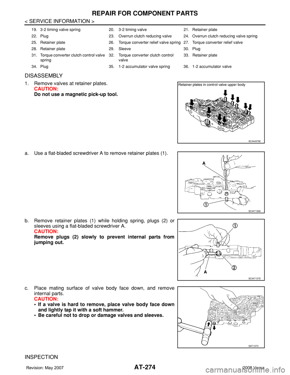
1. Remove valves at retainer plates.
CAUTION:
Do not use a magnetic pick-up tool.
a. Use a flat-bladed screwdriver A to remove retainer plates (1).
b. Remove retainer plates (1) while holding spring, plugs (2) or
sleeves using a flat-bladed screwdriver A.
CAUTION:
Remove plugs (2) slowly to prevent internal parts from
jumping out.
c. Place mating surface of valve body face down, and remove
internal parts.
CAUTION:
• If a valve is hard to remove, place valve body face down
and lightly tap it with a soft hammer.
• Be careful not to drop or damage valves and sleeves.
INSPECTION
19. 3-2 timing valve spring 20. 3-2 timing valve 21. Retainer plate
22. Plug 23. Overrun clutch reducing valve 24. Overrun clutch reducing valve spring
25. Retainer plate 26. Torque converter relief valve spring 27. Torque converter relief valve
28. Retainer plate 29. Sleeve 30. Plug
31. Torque converter clutch control valve
spring32. Torque converter clutch control
valve33. Retainer plate
34. Plug 35. 1-2 accumulator valve spring 36. 1-2 accumulator valve
SCIA4979E
SCIA7136E
SCIA7137E
SAT137D
Page 288 of 2771

AT-276
< SERVICE INFORMATION >
REPAIR FOR COMPONENT PARTS
• Install retainer plates (1).
- While pushing plug or return spring, install retainer plate (1) using
a flat-bladed screwdriver A.
1-2 Accumulator Valve
• Install 1-2 accumulator valve (1), 1-2 accumulator valve spring and
plug. Align 1-2 accumulator retainer plate (2) from opposite side of
control valve body.
• Install 1-2 accumulator valve piston spring (3), 1-2 accumulator
piston (4), plug (5) and retainer plate (6).
Retainer Plate (Control Valve Upper Body)
Install proper retainer plates. Refer to "COMPONENTS".
Unit: mm (in)
Control Valve Lower BodyINFOID:0000000001703382
COMPONENTS
SCIA7139E
SCIA7182E
Lo-
cat-
ionRetainer plate designation Width “A” Length “B”
L14 Pilot valve
6.0 (0.236)21.5 (0.846)
L151-2 accumulator valve
40.5 (1.594)
1-2 accumulator piston
L16 1st reducing valve
21.5 (0.846)
L17 3-2 timing valve
L18 Overrun clutch reducing valve 24.0 (0.945)
L19 Torque converter relief valve 21.5 (0.846)
L20 Torque converter clutch control valve 28.0 (1.102)
L21 Cooler check valve 24.0 (0.945)
SAT086F
Page 329 of 2771
REPAIR FOR COMPONENT PARTS
AT-317
< SERVICE INFORMATION >
D
E
F
G
H
I
J
K
L
MA
B
AT
N
O
P
6. Set drift A [commercial service tool] on differential side bearing
inner race, and press differential side bearing inner race into dif-
ferential case.
CAUTION:
Apply ATF to differential side bearings.
7. Install differential side bearing outer race and differential side
bearing adjusting shim on transaxle case. Refer to AT-318,
"Assembly (1)".
8. Tighten final gear and tighten fixing bolts to the specified torque
in numerical order as shown in the figure after temporarily tight-
ening them. Refer to "COMPONENTS".
SCIA8005E
SCIA8004E
Page 330 of 2771

AT-318
< SERVICE INFORMATION >
ASSEMBLY
ASSEMBLY
Assembly (1)INFOID:0000000001703391
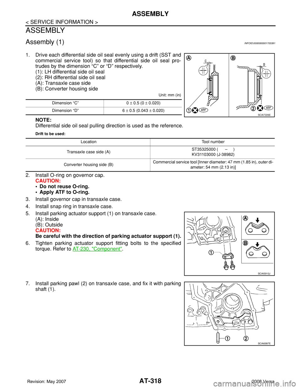
1. Drive each differential side oil seal evenly using a drift (SST and
commercial service tool) so that differential side oil seal pro-
trudes by the dimension “C” or “D” respectively.
(1): LH differential side oil seal
(2): RH differential side oil seal
(A): Transaxle case side
(B): Converter housing side
Unit: mm (in)
NOTE:
Differential side oil seal pulling direction is used as the reference.
Drift to be used:
2. Install O-ring on governor cap.
CAUTION:
• Do not reuse O-ring.
• Apply ATF to O-ring.
3. Install governor cap in transaxle case.
4. Install snap ring in transaxle case.
5. Install parking actuator support (1) on transaxle case.
(A): Inside
(B): Outside
CAUTION:
Be careful with the direction of parking actuator support (1).
6. Tighten parking actuator support fitting bolts to the specified
torque. Refer to AT-230, "
Component".
7. Install parking pawl (2) on transaxle case, and fix it with parking
shaft (1).
Dimension “C” 0 ± 0.5 (0 ± 0.020)
Dimension “D” 6 ± 0.5 (0.043 ± 0.020)
SCIA7226E
Location Tool number
Transaxle case side (A)ST35325000 ( – )
KV31103000 (J-38982)
Converter housing side (B)Commercial service tool [Inner diameter: 47 mm (1.85 in), outer di-
ameter: 54 mm (2.13 in)]
SCIA5910J
SCIA6997E
Page 331 of 2771
ASSEMBLY
AT-319
< SERVICE INFORMATION >
D
E
F
G
H
I
J
K
L
MA
B
AT
N
O
P
8. Install return spring (2) on parking shaft (3) and parking pawl (1)
using a flat-bladed screwdriver.
Adjustment (1)INFOID:0000000001703392
DIFFERENTIAL SIDE BEARING PRELOAD
1. Select proper thickness of differential side bearing adjusting shim using the following procedures.
a. Install differential side bearing outer race without differential side
bearing adjusting shim on transaxle case.
CAUTION:
Apply ATF to differential side bearing outer race.
b. Install differential side bearing outer race on converter housing.
CAUTION:
Apply ATF to differential side bearing outer race.
c. Place final drive assembly on transaxle case.
d. Tighten converter housing fitting bolts (1) and (2) to the specified
torque. Refer to AT-313, "
Final Drive".
SCIA6996E
SAT947DA
Bolt 1 2
Bolt length
[mm (in)]
32.8 (1.291) 40 (1.57)
Number of bolts 10 10
SCIA7970E