2008 INFINITI QX56 tire pressure
[x] Cancel search: tire pressurePage 3288 of 4083
![INFINITI QX56 2008 Factory Service Manual SEC-80
< ECU DIAGNOSIS >[WITH INTELLIGENT KEY SYSTEM]
BCM (BODY CONTROL MODULE)
CONSULT display
Fail-safeIntelligent Key
warning lamp ON Tire pressure
monitor warning lamp ON Reference page
No DTC INFINITI QX56 2008 Factory Service Manual SEC-80
< ECU DIAGNOSIS >[WITH INTELLIGENT KEY SYSTEM]
BCM (BODY CONTROL MODULE)
CONSULT display
Fail-safeIntelligent Key
warning lamp ON Tire pressure
monitor warning lamp ON Reference page
No DTC](/manual-img/42/57030/w960_57030-3287.png)
SEC-80
< ECU DIAGNOSIS >[WITH INTELLIGENT KEY SYSTEM]
BCM (BODY CONTROL MODULE)
CONSULT display
Fail-safeIntelligent Key
warning lamp ON Tire pressure
monitor warning lamp ON Reference page
No DTC is detected.
further testing
may be required. ————
U1000: CAN COMM CIRCUIT ———BCS-30
U1010: CONTROL UNIT (CAN) ———BCS-31
B2190: NATS ANTENNA AMP ———SEC-29
B2191: DIFFERENCE OF KEY ———SEC-32
B2192: ID DISCORD BCM-ECM ———SEC-33
B2193: CHAIN OF BCM-ECM ———SEC-35
B2552: INTELLIGENT KEY ———SEC-37
B2590: NATS MALFUNCTION ———SEC-38
C1704: LOW PRESSURE FL ———WT-31
C1705: LOW PRESSURE FR ———WT-31
C1706: LOW PRESSURE RR ———WT-31
C1707: LOW PRESSURE RL ———WT-31
C1708: [NO DATA] FL ———WT-14
C1709: [NO DATA] FR ———WT-14
C1710: [NO DATA] RR ———WT-14
C1711: [NO DATA] RL ———WT-14
C1712: [CHECKSUM ERR] FL ———WT-16
C1713: [CHECKSUM ERR] FR ———WT-16
C1714: [CHECKSUM ERR] RR ———WT-16
C1715: [CHECKSUM ERR] RL ———WT-16
C1716: [PRESSDATA ERR] FL ———WT-18
C1717: [PRESSDATA ERR] FR ———WT-18
C1718: [PRESSDATA ERR] RR ———WT-18
C1719: [PRESSDATA ERR] RL ———WT-18
C1720: [CODE ERR] FL ———WT-16
C1721: [CODE ERR] FR ———WT-16
C1722: [CODE ERR] RR ———WT-16
C1723: [CODE ERR] RL ———WT-16
C1724: [BATT VOLT LOW] FL ———WT-16
C1725: [BATT VOLT LOW] FR ———WT-16
C1726: [BATT VOLT LOW] RR ———WT-16
C1727: [BATT VOLT LOW] RL ———WT-16
C1729: VHCL SPEED SIG ERR ———WT-19
C1735: IGNITION SIGNAL ———WT-20
Revision: March 2010 2008 QX56
Page 3396 of 4083
SR-20
< ON-VEHICLE REPAIR >
COLLISION DIAGNOSIS
For Side and Ro llover Collision
INFOID:0000000001602211
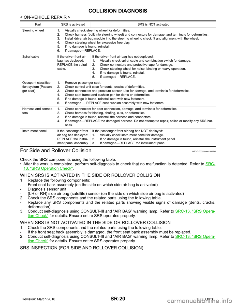
Check the SRS components using the following table.
• After the work is completed, perform self-diagnosis to check that no malfunction is detected. Refer to SRC-
13, "SRS Operation Check".
WHEN SRS IS ACTIVATED IN THE SIDE OR ROLLOVER COLLISION
1. Replace the following components:
- Front seat back assembly (on the side on which side air bag is activated)
- Diagnosis sensor unit
- (LH or RH) side air bag (satellite) sensor (on the side on which side air bag is activated)
2. Check the SRS components and the related parts using the following table.
- Replace any SRS components and the related parts showing visible signs of damage (dents, cracks,
deformation).
3. Conduct self-diagnosis using CONSULT-III and “AIR BAG” warning lamp. Refer to SRC-13, "
SRS Opera-
tion Check" for details. Ensure entire SRS operates properly.
WHEN SRS IS NOT ACTIVATED IN THE SIDE OR ROLLOVER COLLISION
1. Check the SRS components and the related parts using the following table.
- If the front seat back assembly is damaged, the front seat back assembly must be replaced.
2. Conduct self-diagnosis using CONSULT-III and “AIR BAG” warning lamp. Refer to SRC-13, "
SRS Opera-
tion Check" for details. Ensure entire SRS operates properly.
SRS INSPECTION (FOR SIDE AND ROLLOVER COLLISION)
Steering wheel 1. Visually check steering wheel for deformities.
2. Check harness (built into steering wheel) and connectors for damage, and terminals for deformities.
3. Install driver air bag module into the steering wheel to check fit and alignment with the wheel.
4. Check steering wheel for excessive free play.
5. If no damage is found, reinstall.
6. If damaged—REPLACE.
Spiral cable If the driver front air
bag has deployed:
REPLACE the spiral
cable. If the driver front air bag has not deployed:
1. Visually check spiral cable and combination switch for damage.
2. Check connectors and protective tape for damage.
3. Check steering wheel for noise, binding or heavy operation.
4. If no damage is found, reinstall.
5. If damaged—REPLACE.
Occupant classifica-
tion system (Passen-
ger seat) 1. Remove passenger seat.
2. Check control unit case for dents, cracks of deformities.
3. Check connectors and pressure sensor tube for damage, and terminals for deformities.
4. Check seat frame and cushion pan for dents or deformities.
5. If no damage is found, reinstall seat with new fasteners.
6. If damaged — REPLACE seat cushion assembly with new fasteners.
Harness and connec-
tors 1. Check connectors for poor connection, damage, and terminals for deformities.
2. Check harness for binding, chafing, cuts, or deformities.
3. If no damage is found, reinstall the harness and connectors.
4. If damaged—REPLACE the damaged harness. Do not attempt to repair, splice or modify any SRS har-
ness.
Instrument panel If the passenger front air bag has deployed:
REPLACE the instru-
ment panel assembly. If the passenger front air bag has NOT deployed:
1. Visually check instrument panel for damage.
2. If no damage is found, reinstall the instrument panel.
3. If damaged—REPLACE the instrument panel.
Part
SRS is activated SRS is NOT activated
Revision: March 2010 2008 QX56
Page 3506 of 4083
STEERING WHEELST-15
< ON-VEHICLE REPAIR >
C
DE
F
H I
J
K L
M A
B
ST
N
O P
ON-VEHICLE REPAIR
STEERING WHEEL
On-Vehicle Inspection and ServiceINFOID:0000000004920096
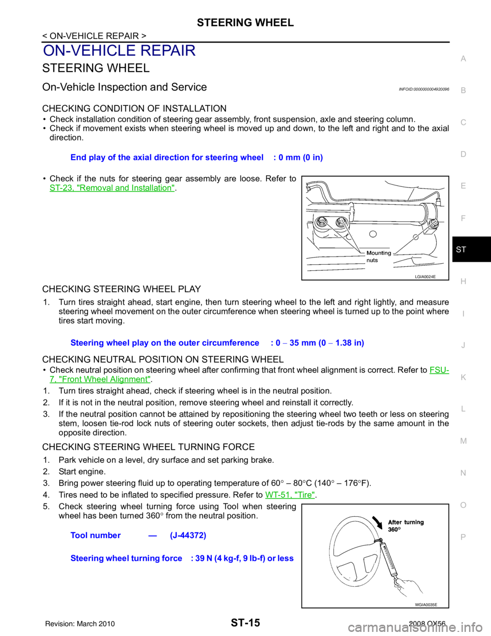
CHECKING CONDITION OF INSTALLATION
• Check installation condition of steering gear assembly, front suspension, axle and steering column.
• Check if movement exists when steering wheel is mo ved up and down, to the left and right and to the axial
direction.
• Check if the nuts for steering gear assembly are loose. Refer to ST-23, "
Removal and Installation".
CHECKING STEERING WHEEL PLAY
1. Turn tires straight ahead, start engine, then turn steer ing wheel to the left and right lightly, and measure
steering wheel movement on the outer circumference when steering wheel is turned up to the point where
tires start moving.
CHECKING NEUTRAL POSITION ON STEERING WHEEL
• Check neutral position on steering wheel after confirming that front wheel alignment is correct. Refer to FSU-
7, "Front Wheel Alignment".
1. Turn tires straight ahead, check if steering wheel is in the neutral position.
2. If it is not in the neutral position, remo ve steering wheel and reinstall it correctly.
3. If the neutral position cannot be attained by repositi oning the steering wheel two teeth or less on steering
stem, loosen tie-rod lock nuts of steering outer socket s, then adjust tie-rods by the same amount in the
opposite direction.
CHECKING STEERING WHEEL TURNING FORCE
1. Park vehicle on a level, dry surface and set parking brake.
2. Start engine.
3. Bring power steering fluid up to operating temperature of 60 ° – 80 °C (140 ° – 176 °F).
4. Tires need to be inflated to specified pressure. Refer to WT-51, "
Tire".
5. Check steering wheel turning force using Tool when steering wheel has been turned 360 ° from the neutral position.
End play of the axial direction
for steering wheel : 0 mm (0 in)
LGIA0024E
Steering wheel play on the outer circumference : 0 − 35 mm (0 − 1.38 in)
Tool number — (J-44372)
Steering wheel turning force : 39 N (4 kg-f, 9 lb-f) or less
WGIA0035E
Revision: March 2010 2008 QX56
Page 3662 of 4083

TCM
TM-115
< ECU DIAGNOSIS >
C EF
G H
I
J
K L
M A
B
TM
N
O P
Even when the electronic circuits are normal, under s pecial conditions (for example, when slamming on the
brake with the wheels spinning drastically and stopping the tire rotation), the transmission can go into fail-safe
mode. If this happens, switch “OFF” the ignition switch for 10 seconds, then switch it “ON” again to return to
the normal shift pattern. Therefore, the customer's vehicle has returned to normal, so handle according to the
“diagnostics flow” (Refer to TM-5, "
Work Flow").
FAIL-SAFE FUNCTION
If any malfunction occurs in a sensor or solenoid, th is function controls the A/T to mark driving possible.
Output Speed Sensor
• Signals are input from two systems - from output s peed sensor installed on the transmission and from com-
bination meter so normal driving is possible even if t here is a malfunction in one of the systems. And if output
speed sensor has unusual cases, 5GR is prohibited.
Accelerator Pedal Position Sensor
• If there is a malfunction in one of the systems, the accelerator opening angle is controlled by ECM according
to a pre-determined accelerator angle to make driving possible. And if there are malfunctions in tow sys-
tems, the engine speed is fixed by ECM to a pre-determined engine speed to make driving possible.
Throttle Position Sensor
• If there is a malfunction in one of the systems, the accelerator opening angle is controlled by ECM according
to a pre-determined accelerator angle to make driving possible. And if there are malfunctions in tow sys-
tems, the accelerator opening angle is controlled by the idle signal sent from the ECM which is based on
input indicating either idle condition or off-idle condition (pre-determined accelerator opening) in order to
make driving possible.
Transmission Range Switch
• In the unlikely event that a malfunction signal enters t he TCM, the position indicator is switched “OFF”, the
starter relay is switched “OFF” (starter starting is disabled), the back-up lamp relay switched “OFF” (back-up
lamp is OFF) and the position is fixed to the “D” range to make driving possible.
Starter Relay
• The starter relay is switched “OFF”. (Starter starting is disabled.)
Interlock
• If there is an interlock judgment malfunction, the tr ansmission is fixed in 2GR to make driving possible.
NOTE:
When the vehicle is driven fixed in 2GR, a inpu t speed sensor malfunction is displayed, but this is
not a input speed sensor malfunction.
• When the interlock is detected at the 3GR or more, it is locked at the 2GR.
1st Engine Braking
• When there is an 1st engine brake judgment malfunction, the low coast brake solenoid is switched “OFF” to
avoid the engine brake operation.
Line Pressure Solenoid
• The solenoid is switched “OFF” and the line pressure is set to the maximum hydraulic pressure to make driv- ing possible.
Torque Converter Clutch Solenoid
• The solenoid is switched “OFF” to release the lock-up.
Low Coast Brake Solenoid
• When a (electrical or functional) malfunction occurs, in order to make driving possible, the engine brake is
not applied in 1GR and 2GR.
Input Clutch Solenoid
• If a (electrical or functional) malfunction occurs with the solenoid either “ON” or “OFF”, the transmission is
held in 4th gear to make driving possible.
Direct Clutch Solenoid
• If a (electrical or functional) malfunction occurs with the solenoid either “ON” or “OFF”, the transmission is
held in 4GR to make driving possible.
Front Brake Solenoid
• If a (electrical or functional) malfunction occurs with the solenoid “ON”, in order to make driving possible, the
A/T is held in 5GR; if the solenoid is OFF, 4GR.
Revision: March 2010 2008 QX56
Page 3734 of 4083
LINE PRESSURE TESTTM-187
< ON-VEHICLE MAINTENANCE >
CEF
G H
I
J
K L
M A
B
TM
N
O P
LINE PRESSURE TEST
Inspection and JudgmentINFOID:0000000001696157
LINE PRESSURE TEST
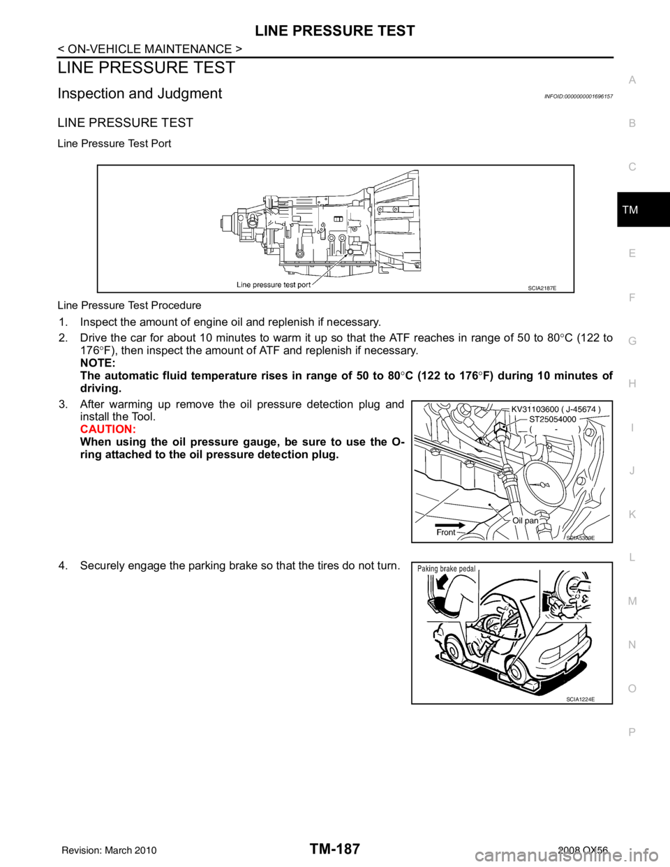
Line Pressure Test Port
Line Pressure Test Procedure
1. Inspect the amount of engine oil and replenish if necessary.
2. Drive the car for about 10 minutes to warm it up so that the ATF reaches in range of 50 to 80 °C (122 to
176° F), then inspect the amount of ATF and replenish if necessary.
NOTE:
The automatic fluid temperature rises in range of 50 to 80 °C (122 to 176° F) during 10 minutes of
driving.
3. After warming up remove the oil pressure detection plug and install the Tool.
CAUTION:
When using the oil pressure ga uge, be sure to use the O-
ring attached to the oil pressure detection plug.
4. Securely engage the parking brake so that the tires do not turn.
SCIA2187E
SCIA5309E
SCIA1224E
Revision: March 2010 2008 QX56
Page 3891 of 4083
![INFINITI QX56 2008 Factory Service Manual WCS-14
< FUNCTION DIAGNOSIS >
DIAGNOSIS SYSTEM (METER)
X: Applicable
Display item [Unit]MAIN
SIGNALS SELECTION
FROM MENU Description
SPEED METER [km/h] or [mph] X X Displays the value of vehicle spee INFINITI QX56 2008 Factory Service Manual WCS-14
< FUNCTION DIAGNOSIS >
DIAGNOSIS SYSTEM (METER)
X: Applicable
Display item [Unit]MAIN
SIGNALS SELECTION
FROM MENU Description
SPEED METER [km/h] or [mph] X X Displays the value of vehicle spee](/manual-img/42/57030/w960_57030-3890.png)
WCS-14
< FUNCTION DIAGNOSIS >
DIAGNOSIS SYSTEM (METER)
X: Applicable
Display item [Unit]MAIN
SIGNALS SELECTION
FROM MENU Description
SPEED METER [km/h] or [mph] X X Displays the value of vehicle speed signal.
SPEED OUTPUT [km/h] or [mph] X XDisplays the value of vehicle speed signal, which is transmitted to
each unit with
CAN communication.
TACHO METER [rpm] XX Displays the value of engine speed signal, which is input from ECM.
FUEL METER [lit.] XXDisplays the value, which processes a resistance signal from fuel
gauge.
W TEMP METER [ °C] or [° F] X XDisplays the value of engine coolant temperature signal, which is in-
put from ECM.
ABS W/L [ON/OFF] X Displays [ON/OFF] condition of ABS warning lamp.
VDC/TCS IND [ON/OFF] X Displays [ON/OFF] condition of VDC OFF indicator lamp.
SLIP IND [ON/OFF] X Displays [ON/OFF] condition of SLIP indicator lamp.
BRAKE W/L [ON/OFF] X Displays [ON/OFF] condition of brake warning lamp.*
DOOR W/L [ON/OFF] X Displays [ON/OFF] condition of door warning lamp.
TRUNK W/L [ON/OFF] X Displays [ON/OFF] condition of glass hatch warning lamp.
HI-BEAM IND [ON/OFF] X Displays [ON/OFF] condition of high beam indicator.
TURN IND [ON/OFF] X Displays [ON/OFF] conditio n of turn indicator.
OIL W/L [ON/OFF] X Displays [ON/OFF] condition of oil pressure warning lamp.
C-ENG W/L [ON/OFF] X Displays [ON/OFF] condition of malfunction indicator lamp.
CRUISE IND [ON/OFF] X Displays [ON/OFF] condition of CRUISE indicator.
SET IND [ON/OFF] X Displays [ON/OFF] condition of SET indicator.
AT CHECK W/L [ON/OFF] X Displays [ON/OFF] condition of AT CHECK warning lamp.
FUEL W/L [ON/OFF] XX Displays [ON/OFF] condition of low-fuel warning lamp.
AIR PRES W/L [ON/OFF] X Displays [ON/OFF] condition of tire pressure warning lamp.
KEY G W/L [ON/OFF] X Displays [ON/OFF] condition of key green warning lamp.
KEY R W/L [ON/OFF] X Displays [ON/OFF] condition of key red warning lamp.
KEY KNOB W/L [ON/OFF] X Displays [ON/OFF] condition of key knob warning lamp.
M RANGE SW [ON/OFF] XX Displays [ON/OFF] condition of manual mode range switch.
NM RANGE SW [ON/OFF] XXDisplays [ON/OFF] condition of except for manual mode range
switch.
AT SFT UP SW [ON/OFF] XX Displays [ON/OFF] condition of A/T shift-up switch.
AT SFT DWN SW [ON/OFF] XX Displays [ON/OF F] condition of A/T shift-down switch.
DISTANCE [km] or [mile] XXDisplays the value, which is calculated by vehicle speed signal, fuel
gauge and fuel consumption from ECM.
BUZZER [ON/OFF] XX Displays [ON/ OFF] condition of buzzer.
BRAKE SW [ON/OFF] X Indicates [ON/OFF] condition of parking brake switch.
AT-M GEAR [1, 2, 3, 4, 5] XX Indicates [1, 2, 3, 4, 5] condition of A/T manual mode gear position.
P RANGE IND [ON/OFF] XX Indicates [ON/OFF] condition of A/T shift P range indicator.
R RANGE IND [ON/OFF] XX Indicates [ON/OFF] condition of A/T shift R range indicator.
N RANGE IND [ON/OFF] XX Indicates [ON/OFF] condition of A/T shift N range indicator.
D RANGE IND [ON/OFF] XX Indicates [ON/OFF] condition of A/T shift D range indicator.
4 RANGE IND [ON/OFF] XX Indicates [ON/OFF] condition of A/T shift 4 range indicator.
3 RANGE IND [ON/OFF] XX Indicates [ON/OFF] condition of A/T shift 3 range indicator.
2 RANGE IND [ON/OFF] XX Indicates [ON/OFF] condition of A/T shift 2 range indicator.
1 RANGE IND [ON/OFF] XX Indicates [ON/OFF] condition of A/T shift 1range indicator.
Revision: March 2010 2008 QX56
Page 3926 of 4083
WCS
COMBINATION METERWCS-49
< ECU DIAGNOSIS >
C
DE
F
G H
I
J
K L
M B A
O P
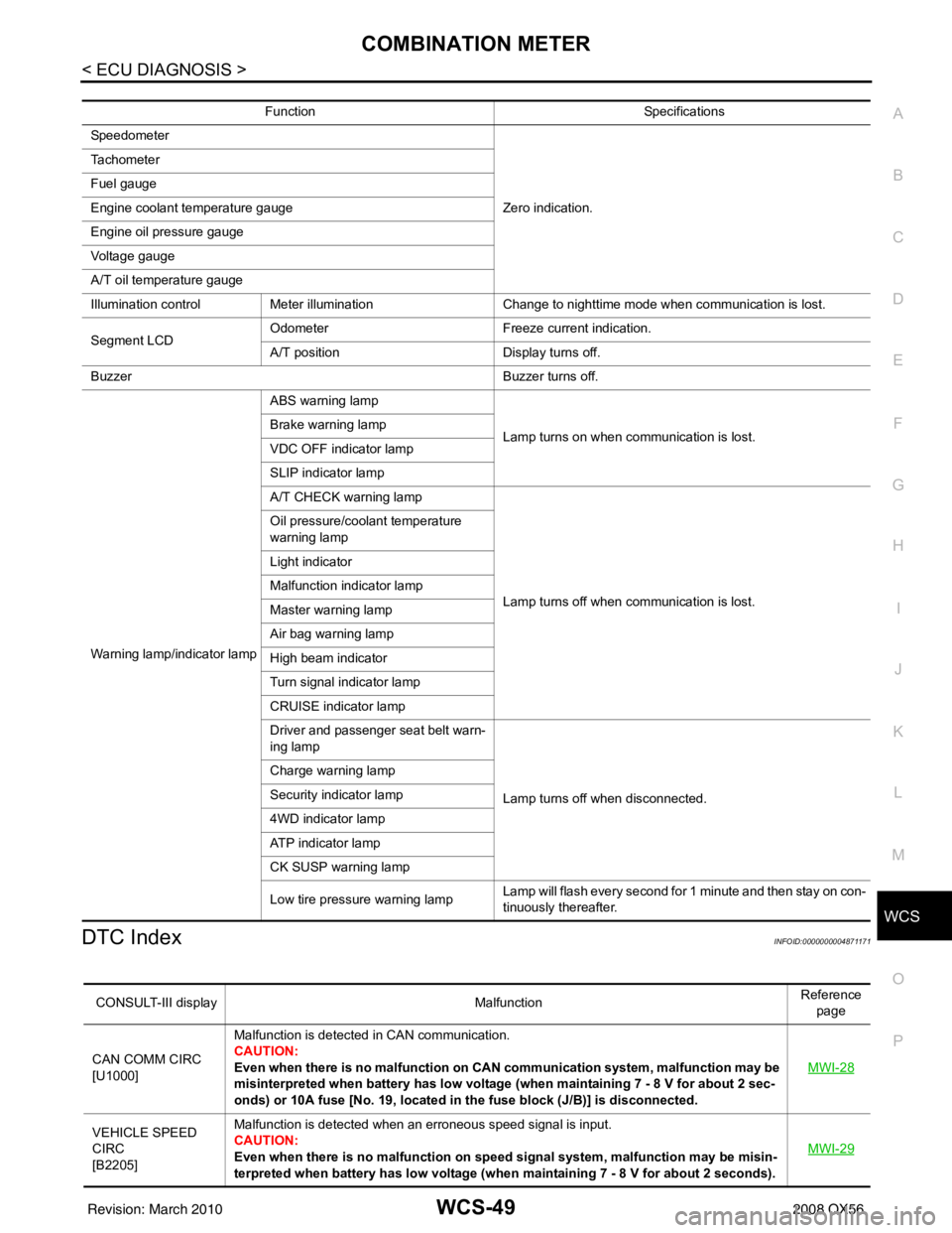
DTC IndexINFOID:0000000004871171
Function Specifications
Speedometer
Zero indication.
Tachometer
Fuel gauge
Engine coolant temperature gauge
Engine oil pressure gauge
Voltage gauge
A/T oil temperature gauge
Illumination control
Meter illumination Change to nighttime mode when communication is lost.
Segment LCD Odometer
Freeze current indication.
A/T position Display turns off.
Buzzer Buzzer turns off.
Warning lamp/indicator lamp ABS warning lamp
Lamp turns on when communication is lost.
Brake warning lamp
VDC OFF indicator lamp
SLIP indicator lamp
A/T CHECK warning lamp
Lamp turns off when communication is lost.
Oil pressure/coolant temperature
warning lamp
Light indicator
Malfunction indicator lamp
Master warning lamp
Air bag warning lamp
High beam indicator
Turn signal indicator lamp
CRUISE indicator lamp
Driver and passenger seat belt warn-
ing lamp
Lamp turns off when disconnected.
Charge warning lamp
Security indicator lamp
4WD indicator lamp
ATP indicator lamp
CK SUSP warning lamp
Low tire pressu
re warning lamp Lamp will flash every second for 1 minute and then stay on con-
tinuously thereafter.
CONSULT-III display
MalfunctionReference
page
CAN COMM CIRC
[U1000] Malfunction is detected in CAN communication.
CAUTION:
Even when there is no ma
lfunction on CAN communication system, malfunction may be
misinterpreted when battery has low voltag e (when maintaining 7 - 8 V for about 2 sec-
onds) or 10A fuse [No. 19, located in the fuse block (J/B)] is disconnected. MWI-28
VEHICLE SPEED
CIRC
[B2205]Malfunction is detected when an erroneous speed signal is input.
CAUTION:
Even when there is no malfunction on speed signal system, malfunction may be misin-
terpreted when battery has low voltage (whe
n maintaining 7 - 8 V for about 2 seconds). MWI-29
Revision: March 2010
2008 QX56
Page 3931 of 4083
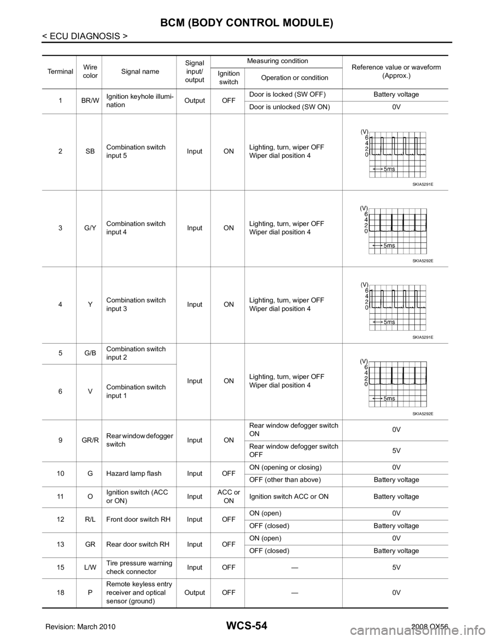
WCS-54
< ECU DIAGNOSIS >
BCM (BODY CONTROL MODULE)
Te r m i n a lWire
color Signal name Signal
input/
output Measuring condition
Reference value or waveform
(Approx.)
Ignition
switch Operation or condition
1BR/W Ignition keyhole illumi-
nation Output OFFDoor is locked (SW OFF)
Battery voltage
Door is unlocked (SW ON) 0V
2SB Combination switch
input 5 Input ON
Lighting, turn, wiper OFF
Wiper dial position 4
3G/Y Combination switch
input 4 Input ONLighting, turn, wiper OFF
Wiper dial position 4
4Y Combination switch
input 3 Input ON
Lighting, turn, wiper OFF
Wiper dial position 4
5G/B Combination switch
input 2
Input ONLighting, turn, wiper OFF
Wiper dial position 4
6V Combination switch
input 1
9GR/R Rear window defogger
switch
Input ONRear window defogger switch
ON
0V
Rear window defogger switch
OFF 5V
10 G Hazard lamp flash Input OFF ON (opening or closing)
0V
OFF (other than above) Battery voltage
11 O Ignition switch (ACC
or ON)
InputACC or
ON Ignition switch ACC or ON
Battery voltage
12 R/L Front door switch RH Input OFF ON (open)
0V
OFF (closed) Battery voltage
13 GR Rear door switch RH Input OFF ON (open)
0V
OFF (closed) Battery voltage
15 L/W Tire pressure warning
check connector
Input OFF
—5V
18 P Remote keyless entry
receiver and optical
sensor (ground)
Output OFF
—0V
SKIA5291E
SKIA5292E
SKIA5291E
SKIA5292E
Revision: March 2010 2008 QX56