2008 INFINITI QX56 tire pressure
[x] Cancel search: tire pressurePage 1405 of 4083
![INFINITI QX56 2008 Factory Service Manual EC-106
< COMPONENT DIAGNOSIS >[VK56DE]
P0101 MAF SENSOR
P0101 MAF SENSOR
Component DescriptionINFOID:0000000001351401
The mass air flow sensor is placed in the stream of intake air. It mea-
sures the INFINITI QX56 2008 Factory Service Manual EC-106
< COMPONENT DIAGNOSIS >[VK56DE]
P0101 MAF SENSOR
P0101 MAF SENSOR
Component DescriptionINFOID:0000000001351401
The mass air flow sensor is placed in the stream of intake air. It mea-
sures the](/manual-img/42/57030/w960_57030-1404.png)
EC-106
< COMPONENT DIAGNOSIS >[VK56DE]
P0101 MAF SENSOR
P0101 MAF SENSOR
Component DescriptionINFOID:0000000001351401
The mass air flow sensor is placed in the stream of intake air. It mea-
sures the intake flow rate by measuring a part of the entire intake
flow. The mass air flow sensor c
ontrols the temperature of the hot
wire to a certain amount. The heat generated by the hot wire is
reduced as the intake air flows around it. The more air, the greater
the heat loss.
Therefore, the electric current supplied to the hot wire is changed to
maintain the temperature of the hot wire as air flow increases. The
ECM detects the air flow by means of this current change.
On Board Diagn osis LogicINFOID:0000000001351403
DTC Confirmation ProcedureINFOID:0000000001351404
Perform PROCEDURE FOR MALFUNCTION A first.
If the DTC cannot be confirmed, perform PROCEDURE FOR MALFUNCTION B.
NOTE:
If DTC Confirmation Procedure has been previously conducted, always turn ignition switch OFF and wait at
least 10 seconds before conducting the next test.
PROCEDURE FOR MALFUNCTION A
NOTE:
If engine will not start or stops soon, wait at leas t 10 seconds with engine stopped (Ignition switch ON) instead
of running engine at idle speed.
With CONSULT-III
1. Start engine and warm it up to normal operating temperature.
2. Run engine for at least 10 seconds at idle speed.
3. Check 1st trip DTC.
4. If 1st trip DTC is detected, go to EC-109, "
Diagnosis Procedure".
With GST
Follow the procedure “With CONSULT-III” above.
PROCEDURE FOR MALFUNCTION B
NOTE:
Check vehicle specifications and VIN, then select the procedure to be performed. (Refer to the table below.)
BBIA0355E
DTC No. Trouble diagnosis name DTC detecting conditionPossible cause
P0101
0101 Mass air flow sensor circuit
range/performance A)
A high voltage from the sensor is sent to ECM
under light load driving condition. • Harness or connectors
(The sensor circuit is open or
shorted.)
• Mass air flow sensor
• EVAP control system pressure sensor
• Intake air temperature sensor
B) A low voltage from the sensor is sent to ECM
under heavy load driving condition. • Harness or connectors
(The sensor circuit is open or
shorted.)
• Intake air leaks
• Mass air flow sensor
• EVAP control system pressure sensor
• Intake air temperature sensor
Revision: March 2010 2008 QX56
Page 1797 of 4083
![INFINITI QX56 2008 Factory Service Manual EC-498
< ON-VEHICLE REPAIR >[VK56DE]
EVAP CANISTER
ON-VEHICLE REPAIR
EVAP CANISTER
Component InspectionINFOID:0000000006054101
EVAP CANISTER
Check EVAP canister as follows:
1. Block port
(B).
2. Blow INFINITI QX56 2008 Factory Service Manual EC-498
< ON-VEHICLE REPAIR >[VK56DE]
EVAP CANISTER
ON-VEHICLE REPAIR
EVAP CANISTER
Component InspectionINFOID:0000000006054101
EVAP CANISTER
Check EVAP canister as follows:
1. Block port
(B).
2. Blow](/manual-img/42/57030/w960_57030-1796.png)
EC-498
< ON-VEHICLE REPAIR >[VK56DE]
EVAP CANISTER
ON-VEHICLE REPAIR
EVAP CANISTER
Component InspectionINFOID:0000000006054101
EVAP CANISTER
Check EVAP canister as follows:
1. Block port
(B).
2. Blow air into port (A) and confirm that it flows freely out of port
(C) .
3. Release blocked port (B) .
4. Apply vacuum pressure to port (B) and confirm that vacuum
pressure exists at the ports (A) and (C).
5. Block port (A) and (B).
6. Apply pressure to port (C) and check that there is no leakage.
Removal and InstallationINFOID:0000000006211822
EVAP CANISTER
Tighten EVAP canister as shown in the figure.
REMOVAL
1. Remove the left rear wheel and tire using power tool.
2. Disconnect the EVAP canister control pressure sensor hose.
3. Disconnect the EVAP canister c ontrol pressure sensor connector
4. Remove the EVAP canister control pres sure sensor and O-ring, if necessary.
5. Disconnect the fuel tank EVAP breather hose.
6. Remove the seat belt latch anchor.
7. Disconnect the EVAP canister vent control valve connector.
8. Disconnect the EVAP canister vent control valve hose.
9. Remove the EVAP canister retaining bolt.
10. Remove the EVAP canister.
11. Remove the EVAP canister vent c ontrol valve and O-ring, if necessary.
PBIB1212E
: N·m (kg-m, ft-lb)
BBIA0349E
Revision: March 2010 2008 QX56
Page 1798 of 4083
![INFINITI QX56 2008 Factory Service Manual EVAP CANISTEREC-499
< ON-VEHICLE REPAIR > [VK56DE]
C
D
E
F
G H
I
J
K L
M A
EC
NP
O
Installation
Installation is in the reverse order of removal.
CAUTION:
Always replace O-rings with a new one.
EVAP CA INFINITI QX56 2008 Factory Service Manual EVAP CANISTEREC-499
< ON-VEHICLE REPAIR > [VK56DE]
C
D
E
F
G H
I
J
K L
M A
EC
NP
O
Installation
Installation is in the reverse order of removal.
CAUTION:
Always replace O-rings with a new one.
EVAP CA](/manual-img/42/57030/w960_57030-1797.png)
EVAP CANISTEREC-499
< ON-VEHICLE REPAIR > [VK56DE]
C
D
E
F
G H
I
J
K L
M A
EC
NP
O
Installation
Installation is in the reverse order of removal.
CAUTION:
Always replace O-rings with a new one.
EVAP CANISTER CONTROL PRESSURE SENSOR
REMOVAL
1. Remove the left rear wheel and tire using power tool.
2. Disconnect the fuel t
ank EVAP breather hose.
3. Disconnect the EVAP canister control pressure sensor connector.
4. Remove the EVAP canister control pressure sensor and O-ring.
Installation
Installation is in the reverse order of removal.
CAUTION:
Always replace O-ring with a new one.
EVAP CANISTER VENT CONTROL VALVE
REMOVAL
1. Remove the left rear wheel and tire using power tool.
2. Disconnect the EVAP canister vent control valve connector.
3. Disconnect the EVAP canister vent control valve hose.
4. Turn EVAP canister vent control valve counterclockwise.
5. Remove the EVAP canister vent control valve and O-ring.
Installation
Installation is in the reverse order of removal.
CAUTION:
Always replace O-ring with a new one.
BBIA0350E
Revision: March 2010 2008 QX56
Page 2038 of 4083
EXL-110
< ON-VEHICLE REPAIR >
ADJUSTMENT AND INSPECTION
ON-VEHICLE REPAIR
ADJUSTMENT AND INSPECTION
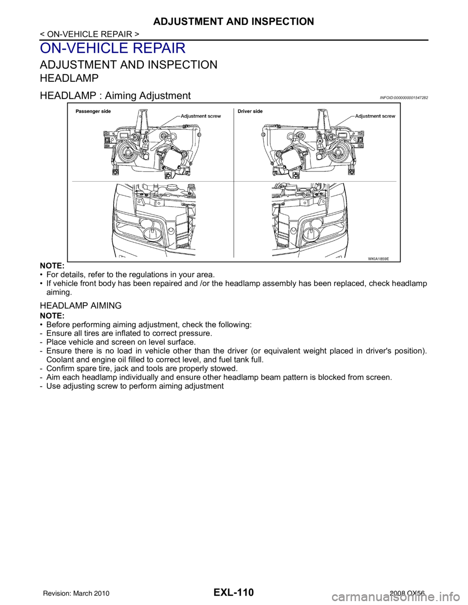
HEADLAMP
HEADLAMP : Aiming AdjustmentINFOID:0000000001547282
NOTE:
• For details, refer to the regulations in your area.
• If vehicle front body has been repaired and /or the headlamp assembly has been replaced, check headlamp
aiming.
HEADLAMP AIMING
NOTE:
• Before performing aiming adjustment, check the following:
- Ensure all tires are inflated to correct pressure.
- Place vehicle and screen on level surface.
- Ensure there is no load in vehicle other than the driver (or equivalent weight placed in driver's position).
Coolant and engine oil filled to correct level, and fuel tank full.
- Confirm spare tire, jack and tools are properly stowed.
- Aim each headlamp individually and ensure other headlamp beam pattern is blocked from screen.
- Use adjusting screw to perform aiming adjustment
WKIA1859E
Revision: March 2010 2008 QX56
Page 2039 of 4083
ADJUSTMENT AND INSPECTIONEXL-111
< ON-VEHICLE REPAIR >
C
DE
F
G H
I
J
K
M A
B
EXL
N
O P
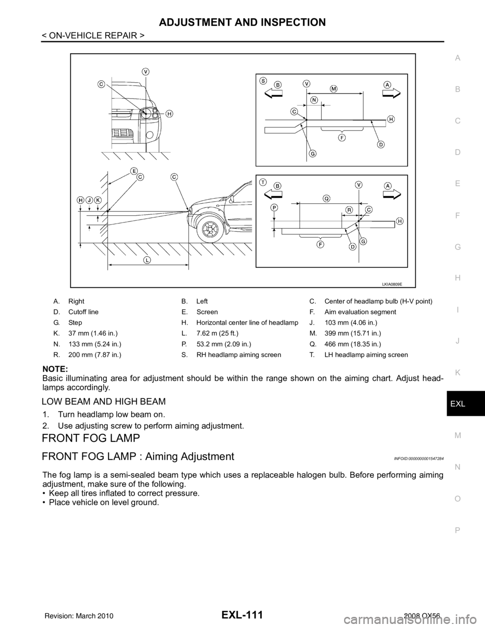
NOTE:
Basic illuminating area for adjustment should be within the range shown on the aiming chart. Adjust head-
lamps accordingly.
LOW BEAM AND HIGH BEAM
1. Turn headlamp low beam on.
2. Use adjusting screw to perform aiming adjustment.
FRONT FOG LAMP
FRONT FOG LAMP : Aiming AdjustmentINFOID:0000000001547284
The fog lamp is a semi-sealed beam type which uses a replaceable halogen bulb. Before performing aiming
adjustment, make sure of the following.
• Keep all tires inflated to correct pressure.
• Place vehicle on level ground.
A. Right B. LeftC. Center of headlamp bulb (H-V point)
D. Cutoff line E. ScreenF. Aim evaluation segment
G. Step H. Horizontal center line of headlamp J. 103 mm (4.06 in.)
K. 37 mm (1.46 in.) L. 7.62 m (25 ft.)M. 399 mm (15.71 in.)
N. 133 mm (5.24 in.) P. 53.2 mm (2.09 in.)Q. 466 mm (18.35 in.)
R. 200 mm (7.87 in.) S. RH headlamp aiming screen T. LH headlamp aiming screen
LKIA0809E
Revision: March 2010 2008 QX56
Page 2107 of 4083
FUEL LEVEL SENSOR UNIT, FUEL FILTER AND FUEL PUMP ASSEMBLYFL-7
< REMOVAL AND INSTALLATION >
C
DE
F
G H
I
J
K L
M A
FL
NP
O
REMOVAL AND INSTALLATION
FUEL LEVEL SENSOR UNIT, FUEL FI
LTER AND FUEL PUMP ASSEMBLY
Removal and InstallationINFOID:0000000004900805
REMOVAL
WARNING:
Follow the “General Precautions” before working on the fuel system. Refer to FL-4, "
General Precau-
tion" .
1. Remove the fuel filler cap to release the pressure from inside the fuel tank.
2. Check the fuel level on level gauge. If the fuel gauge indicates more than the level as shown (full or almost full), drain the fuel
from the fuel tank until the fuel gauge indicates the level as
shown, or less.
• If the fuel pump does not operate, use the following procedureto drain the fuel to the specified level.
a. Insert a suitable hose of less than 15 mm (0.59 in) diameter into the fuel filler pipe through the fuel filler opening to drain the fuel
from fuel filler pipe.
b. Remove the LH rear wheel and tire. Refer to WT-48, "
Rotation" .
c. Remove the four clips and remove the rear fender protector, front.
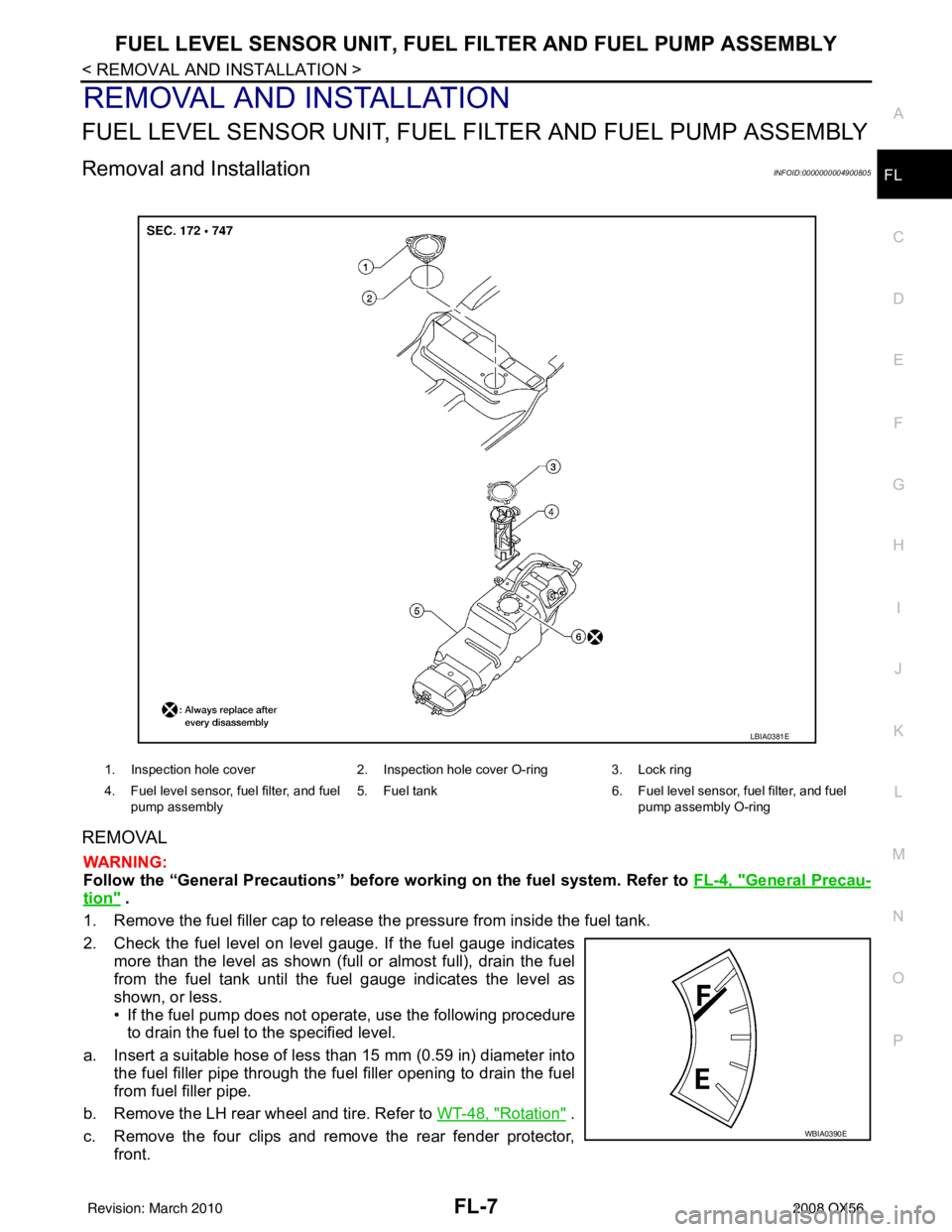
1. Inspection hole cover 2. Inspection hole cover O-ring 3. Lock ring
4. Fuel level sensor, fuel filter, and fuel pump assembly 5. Fuel tank
6. Fuel level sensor, fuel filter, and fuel
pump assembly O-ring
LBIA0381E
WBIA0390E
Revision: March 2010 2008 QX56
Page 2112 of 4083
FL-12
< REMOVAL AND INSTALLATION >
FUEL TANK
REMOVAL
WARNING:
Follow the “General Precautions” before working on the fuel system. Refer to FL-4, "
General Precau-
tion" .
1. Drain the fuel from the fuel tank, if necessary. • Position the vehicle so it is level.
2. Remove the fuel filler cap to release the pressure from inside the fuel tank.
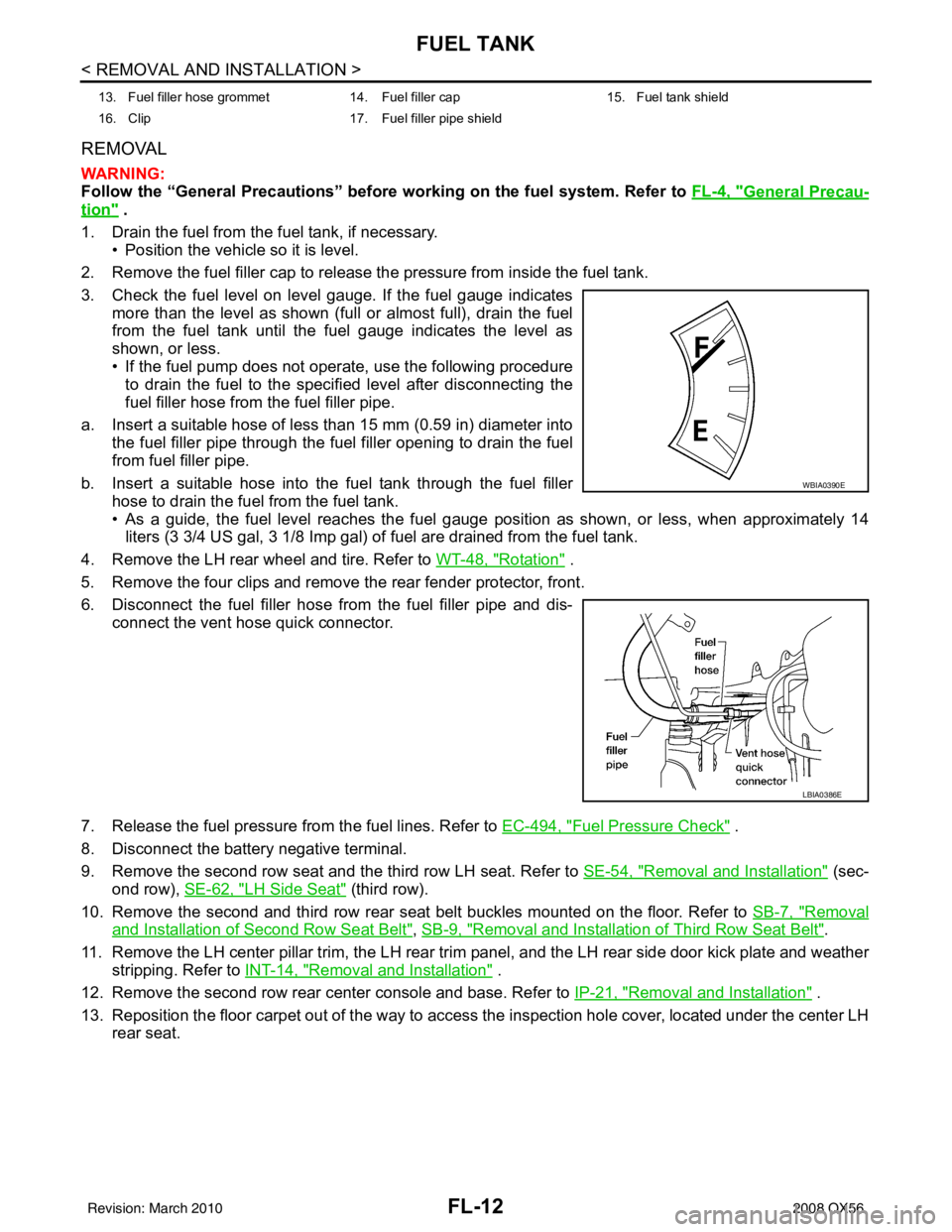
3. Check the fuel level on level gauge. If the fuel gauge indicates more than the level as shown (full or almost full), drain the fuel
from the fuel tank until the fuel gauge indicates the level as
shown, or less.
• If the fuel pump does not operate, use the following procedure
to drain the fuel to the specified level after disconnecting the
fuel filler hose from the fuel filler pipe.
a. Insert a suitable hose of less than 15 mm (0.59 in) diameter into the fuel filler pipe through the fuel filler opening to drain the fuel
from fuel filler pipe.
b. Insert a suitable hose into the fuel tank through the fuel filler hose to drain the fuel from the fuel tank.
• As a guide, the fuel level reaches the fuel gauge position as shown, or less, when approximately 14
liters (3 3/4 US gal, 3 1/8 Imp gal) of fuel are drained from the fuel tank.
4. Remove the LH rear wheel and tire. Refer to WT-48, "
Rotation" .
5. Remove the four clips and remove the rear fender protector, front.
6. Disconnect the fuel filler hose from the fuel filler pipe and dis- connect the vent hose quick connector.
7. Release the fuel pressure from the fuel lines. Refer to EC-494, "
Fuel Pressure Check" .
8. Disconnect the battery negative terminal.
9. Remove the second row seat and the third row LH seat. Refer to SE-54, "
Removal and Installation" (sec-
ond row), SE-62, "
LH Side Seat" (third row).
10. Remove the second and third row rear seat belt buckles mounted on the floor. Refer to SB-7, "
Removal
and Installation of Second Row Seat Belt", SB-9, "Removal and Installation of Third Row Seat Belt".
11. Remove the LH center pillar trim, the LH rear trim panel, and the LH rear side door kick plate and weather
stripping. Refer to INT-14, "
Removal and Installation" .
12. Remove the second row rear center console and base. Refer to IP-21, "
Removal and Installation" .
13. Reposition the floor carpet out of the way to access the inspection hole cover, located under the center LH
rear seat.
13. Fuel filler hose grommet 14. Fuel filler cap 15. Fuel tank shield
16. Clip 17. Fuel filler pipe shield
WBIA0390E
LBIA0386E
Revision: March 2010 2008 QX56
Page 2124 of 4083
ON-VEHICLE SERVICEFSU-7
< ON-VEHICLE MAINTENANCE >
C
DF
G H
I
J
K L
M A
B
FSU
N
O P
ON-VEHICLE MAINTENANCE
ON-VEHICLE SERVICE
Front Suspension PartsINFOID:0000000001534627
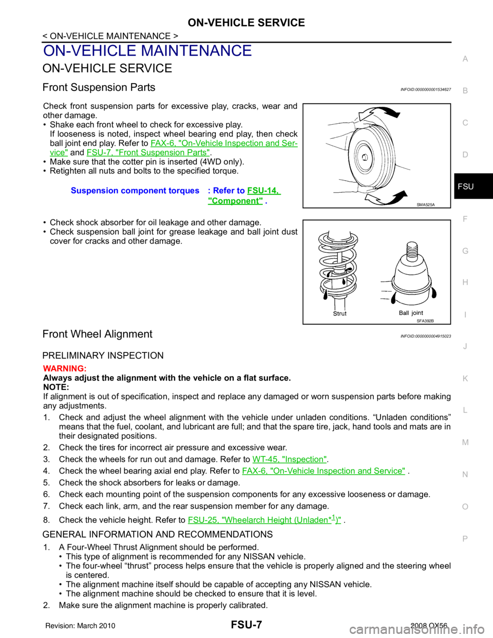
Check front suspension parts for excessive play, cracks, wear and
other damage.
• Shake each front wheel to check for excessive play. If looseness is noted, inspect wheel bearing end play, then check
ball joint end play. Refer to FA X - 6 , "
On-Vehicle Inspection and Ser-
vice" and FSU-7, "Front Suspension Parts".
• Make sure that the cotter pin is inserted (4WD only).
• Retighten all nuts and bolts to the specified torque.
• Check shock absorber for oil leakage and other damage.
• Check suspension ball joint for grease leakage and ball joint dust cover for cracks and other damage.
Front Wheel AlignmentINFOID:0000000004915023
PRELIMINARY INSPECTION
WARNING:
Always adjust the alignment with the vehicle on a flat surface.
NOTE:
If alignment is out of specificat ion, inspect and replace any damaged or worn suspension parts before making
any adjustments.
1. Check and adjust the wheel alignment with the vehicle under unladen conditions. “Unladen conditions”
means that the fuel, coolant, and lubricant are full; and that the spare tire, jack, hand tools and mats are in
their designated positions.
2. Check the tires for incorrect air pressure and excessive wear.
3. Check the wheels for run out and damage. Refer to WT-45, "
Inspection".
4. Check the wheel bearing axial end play. Refer to FAX-6, "
On-Vehicle Inspection and Service" .
5. Check the shock absorbers for leaks or damage.
6. Check each mounting point of the suspension components for any excessive looseness or damage.
7. Check each link, arm, and the rear suspension member for any damage.
8. Check the vehicle height. Refer to FSU-25, "
Wheelarch Height (Unladen*1)" .
GENERAL INFORMATION AND RECOMMENDATIONS
1. A Four-Wheel Thrust Alignment should be performed.
• This type of alignment is re commended for any NISSAN vehicle.
• The four-wheel “thrust” process helps ensure that the vehicle is properly aligned and the steering wheel
is centered.
• The alignment machine itself should be ca pable of accepting any NISSAN vehicle.
• The alignment machine should be checked to ensure that it is level.
2. Make sure the alignment machine is properly calibrated. Suspension component torques : Refer to
FSU-14,
"Component" . SMA525A
SFA392B
Revision: March 2010 2008 QX56