2008 INFINITI QX56 tire pressure
[x] Cancel search: tire pressurePage 2236 of 4083
COMPRESSORHA-31
< ON-VEHICLE REPAIR >
C
DE
F
G H
J
K L
M A
B
HA
N
O P
COMPRESSOR
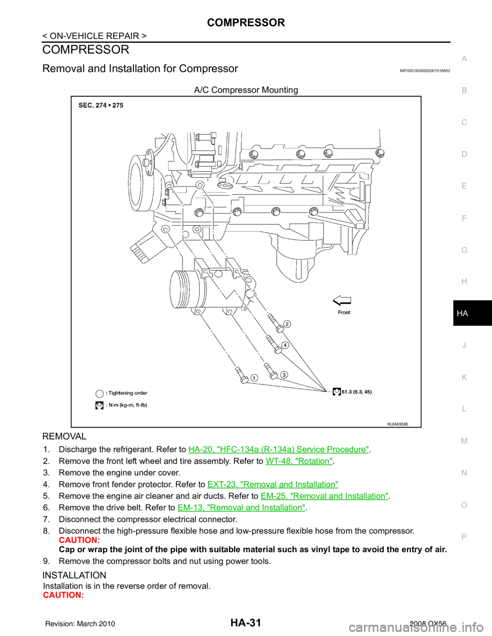
Removal and Installation for CompressorINFOID:0000000001516652
A/C Compressor Mounting
REMOVAL
1. Discharge the refrigerant. Refer to HA-20, "HFC-134a (R-134a) Service Procedure".
2. Remove the front left wheel and tire assembly. Refer to WT-48, "
Rotation".
3. Remove the engine under cover.
4. Remove front fender protector. Refer to EXT-23, "
Removal and Installation"
5. Remove the engine air cleaner and air ducts. Refer to EM-25, "Removal and Installation".
6. Remove the drive belt. Refer to EM-13, "
Removal and Installation".
7. Disconnect the compressor electrical connector.
8. Disconnect the high-pressure flexible hose and low-pressure flexible hose from the compressor. CAUTION:
Cap or wrap the joint of the pipe with suitable mate rial such as vinyl tape to avoid the entry of air.
9. Remove the compressor bolts and nut using power tools.
INSTALLATION
Installation is in the reverse order of removal.
CAUTION:
WJIA0958E
Revision: March 2010 2008 QX56
Page 2244 of 4083
LOW-PRESSURE PIPEHA-39
< ON-VEHICLE REPAIR >
C
DE
F
G H
J
K L
M A
B
HA
N
O P
5. Remove the front and rear bumper fascia. Refer to EXT-13, "Removal and Installation" (front), EXT-15,
"Removal and Installation" (rear).
6. Reposition the front fender protector out of the way. Refer to EXT-23, "
Removal and Installation".
7. Disconnect the chassis harness connector.
8. Remove the spare wheel and tire.
9. Remove the tailpipe and tailpipe hanger bracket. Refer to EX-6, "
Removal and Installation".
10. Remove the seatbelt latch anchor. Refer to EX-6, "
Removal and Installation".
11. Remove the front floor heat shield.
12. Disconnect each end of the underfloor rear high- and low-pressure A/C and heater core pipes. Refer to HA-29, "
Component".
CAUTION:
Cap or wrap the joint of the pipes with suitable material such as viny l tape to avoid the entry of air.
13. Set two suitable jacks at the RH body mount points to support the vehicle body when it is separated from the RH side of the frame.
14. Remove the RH body mount bolts. Refer to BRM-2, "
Body Mounting".
15. Use the vehicle hoist to lower the RH side of the frame from the RH side of the body [approximately 305 mm (12 in)] until there is sufficient clearance to remove the underfloor rear high- and low-pressure A/C
and heater core pipes from between the body and the frame.
16. Remove the underfloor rear high- and low-pressure A/C and heater core pipes from the back of the vehi- cle.
INSTALLATION
Installation is in the reverse order of removal.
CAUTION:
• Replace the O-rings of the underfloor rear high - and low-pressure A/C and heater core pipes with
new ones, then apply compressor oil to them for installation.
• After charging refrigerant, check for leaks.
Revision: March 2010 2008 QX56
Page 2246 of 4083
HIGH-PRESSURE PIPEHA-41
< ON-VEHICLE REPAIR >
C
DE
F
G H
J
K L
M A
B
HA
N
O P
HIGH-PRESSURE PIPE
Removal and Installation for High-Pressure PipeINFOID:0000000001516657
REMOVAL
1. Remove the cowl top extension. Refer to EXT-18, "Removal and Installation".
2. Disconnect the battery negative terminal and positive battery terminal.
3. Reposition the IPDM E/R aside.
4. Remove the front right wheel and tire assembly. Refer to WT-48, "
Rotation".
5. Remove front right fender protector. Refer to EXT-23, "
Removal and Installation"
6. Position aside the front floor insulator.
7. Discharge the refrigerant. Refer to HA-20, "
HFC-134a (R-134a) Service Procedure".
8. Remove the low pressure pipe. Refer to HA-37, "
Removal and Installation for Low-Pressure Pipe".
9. Remove the high-pressure pipe. CAUTION:
Cap or wrap the joint of the pipe with suitable mate rial such as vinyl tape to avoid the entry of air.
INSTALLATION
Installation is in the reverse order of removal.
Refer to HA-29, "
Component".
CAUTION:
• Replace the O-ring of the high-pressure pipe with a new one, then apply compressor oil to it when
installing it.
• After charging refrigerant, check for leaks.
Removal and Installation for Rear High- and Low-Pressure A/C and Heater Core Pipes
INFOID:0000000002975448
REMOVAL
1. Discharge the refrigerant from the A/C system. Refer to HA-20, "HFC-134a (R-134a) Service Procedure".
2. Drain the coolant from the engine cooling system. Refer to CO-11, "
Changing Engine Coolant".
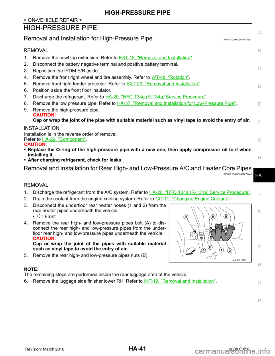
3. Disconnect the underfloor rear heater hoses (1 and 2) from the rear heater pipes underneath the vehicle.
• : Front
4. Remove the rear high- and low-pressure pipes bolt (A) to dis- connect the rear high- and low-pressure pipes from the under-
floor rear high- and low-pressure pipes underneath the vehicle.
CAUTION:
Cap or wrap the joint of the pipes with suitable material
such as vinyl tape to avo id the entry of air.
5. Remove the rear high- and low-pressure pipes nuts (B).
NOTE:
The remaining steps are performed inside the rear luggage area of the vehicle.
6. Remove the luggage side finisher lower RH. Refer to INT-19, "
Removal and Installation".
ALIIA0216ZZ
Revision: March 2010 2008 QX56
Page 2248 of 4083
HIGH-PRESSURE PIPEHA-43
< ON-VEHICLE REPAIR >
C
DE
F
G H
J
K L
M A
B
HA
N
O P
• Replace the O-rings on the rear high- and low-pr essure A/C pipes with a new ones, then apply com-
pressor oil to them for installation.
• After charging the refrigerant, check for leaks.
Removal and Installation for Underfloor Rear High- and Lo w-Pressure A/C and Heater
Core Pipes
INFOID:0000000002975449
REMOVAL
1. Drain the engine coolant. Refer to CO-11, "Changing Engine Coolant".
2. Disconnect the battery negative terminal.
3. Disconnect the generator harness.
4. Discharge the refrigerant. Refer to HA-20, "
HFC-134a (R-134a) Service Procedure".
5. Remove the front and rear bumper fascia. Refer to EXT-13, "
Removal and Installation" (front), EXT-15,
"Removal and Installation" (rear).
6. Reposition the front fender protector out of the way. Refer to EXT-23, "
Removal and Installation".
7. Disconnect the chassis harness connector.
8. Remove the spare wheel and tire.
9. Remove the tailpipe and tailpipe hanger bracket. Refer to EX-6, "
Removal and Installation".
10. Remove the seatbelt latch anchor. Refer to EX-6, "
Removal and Installation".
11. Remove the front floor heat shield.
12. Disconnect each end of the underfloor rear high- and low-pressure A/C and heater core pipes. Refer to HA-29, "
Component".
CAUTION:
Cap or wrap the joint of the pipes with suitable material such as viny l tape to avoid the entry of air.
13. Set two suitable jacks at the RH body mount points to support the vehicle body when it is separated from the RH side of the frame.
14. Remove the RH body mount bolts. Refer to BRM-2, "
Body Mounting".
15. Use the vehicle hoist to lower the RH side of the frame from the RH side of the body [approximately 305 mm (12 in)] until there is sufficient clearance to remove the underfloor rear high- and low-pressure A/C
and heater core pipes from between the body and the frame.
16. Remove the underfloor rear high- and low-pressure A/C and heater core pipes from the back of the vehi- cle.
INSTALLATION
Installation is in the reverse order of removal.
CAUTION:
• Replace the O-rings of the underfloor rear high - and low-pressure A/C and heater core pipes with
new ones, then apply compressor oil to them for installation.
• After charging refrigerant, check for leaks.
Revision: March 2010 2008 QX56
Page 2541 of 4083
![INFINITI QX56 2008 Factory Service Manual LAN-46
< FUNCTION DIAGNOSIS >[CAN]
CAN COMMUNICATION SYSTEM
NOTE:
CAN data of the air bag diagnosis sensor unit is not us
ed by usual service work, thus it is omitted.
Tire pressure data signal R T
T INFINITI QX56 2008 Factory Service Manual LAN-46
< FUNCTION DIAGNOSIS >[CAN]
CAN COMMUNICATION SYSTEM
NOTE:
CAN data of the air bag diagnosis sensor unit is not us
ed by usual service work, thus it is omitted.
Tire pressure data signal R T
T](/manual-img/42/57030/w960_57030-2540.png)
LAN-46
< FUNCTION DIAGNOSIS >[CAN]
CAN COMMUNICATION SYSTEM
NOTE:
CAN data of the air bag diagnosis sensor unit is not us
ed by usual service work, thus it is omitted.
Tire pressure data signal R T
Tire pressure signal R TR
Turn indicator signal TR
Buzzer output signal TR
Door lock/unlock request signal RT
Hazard request signal RT
Hazard warning lamp request signal RT
Ignition knob switch signal RT
KEY warning signal TR
LOCK warning signal TR
Panic alarm request signal RT
Power window open request signal RT
1st position switch signal R T
4th position switch signal R T
Distance to empty signal RT
Fuel level low warning signal RT
Fuel level sensor signal R T
Parking brake switch signal RT
Seat belt buckle switch signal RT
Stop lamp switch signal R T
Tow mode switch signal R T
Vehicle speed signal RRR RRR R T
RRRT
Steering angle sensor signal TR
ABS malfunction signal RT
ABS warning lamp signal RT
Brake pressure sensor signal RT
Brake warning lamp signal RT
SLIP indicator lamp signal RT
TCS malfunction signal RT
VDC malfunction signal RT
VDC OFF indicator lamp signal RRT
VDC operation signal RT
Front wiper stop position signal RT
High beam status signal R T
Hood switch signal RT
Low beam status signal R T
Rear window defogger control signal R RT
Ambient sensor signal RT
Signal name/Connecting unit
ECM
TCM
LASER ICC
ADP
AV
BCM
HVAC I-KEY M&A
STRG 4WDABS
IPDM-E
Revision: March 2010 2008 QX56
Page 2604 of 4083
MA-6
< ON-VEHICLE MAINTENANCE >
GENERAL MAINTENANCE
ON-VEHICLE MAINTENANCE
GENERAL MAINTENANCE
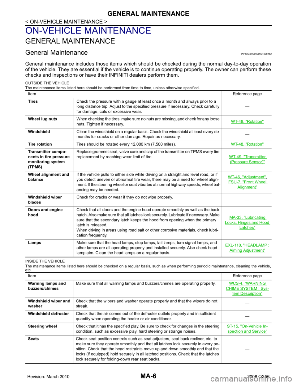
General MaintenanceINFOID:0000000001606163
General maintenance includes those items which should be checked during the normal day-to-day operation
of the vehicle. They are essential if the vehicle is to continue operating properly. The owner can perform these
checks and inspections or have thei r INFINITI dealers perform them.
OUTSIDE THE VEHICLE
The maintenance items listed here should be performed fr om time to time, unless otherwise specified.
INSIDE THE VEHICLE
The maintenance items listed here should be checked on a regular basis, such as when performing periodic maintenance, cleaning the vehicle,
etc.
Item Reference page
Tires Check the pressure with a gauge at least once a month and always prior to a
long distance trip. Adjust to the specified pressure if necessary. Check carefully
for damage, cuts or excessive wear. —
Wheel lug nuts When checking the tires, make sure no nuts are missing, and check for any loose
nuts. Tighten if necessary. WT-48, "
Rotation"
Windshield
Clean the windshield on a regular basis. Check the windshield at least every six
months for cracks or other damage. Repair as necessary. —
Tire rotation Tires should be rotated every 12,000 km (7,500 miles). WT-48, "
Rotation"
Transmitter compo-
nents in tire pressure
monitoring system
(TPMS)Replace grommet seat, valve core and cap of the transmitter on TPMS every tire
replacement by reaching wear limit of tire.
WT-49, "
Transmitter
(Pressure Sensor)"
Wheel alignment and
balanceIf the vehicle pulls to either side while driving on a straight and level road, or if
you detect uneven or abnormal tire wear, there may be a need for wheel align-
ment. If the steering wheel or seat vibrates at normal highway speeds, wheel bal-
ancing may be needed. WT-46, "Adjustment",
FSU-7, "
Front Wheel
Alignment"
Windshield wiper
blades Check for cracks or wear if they do not wipe properly.
—
Doors and engine
hood Check that all doors and the engine hood operate smoothly as well as the back
hatch. Also make sure that all latches lock securely. Lubricate if necessary. Make
sure that the secondary latch keeps the hood from opening when the primary
latch is released.
When driving in areas using road salt or other corrosive materials, check lubri-
cation frequently. MA-33, "
Lubricating
Locks, Hinges and Hood
Latches"
Lamps
Make sure that the head lamps, stop lamps, tail lamps, turn signal lamps, and
other lamps are all operating properly and installed securely. Also check head
lamp aim. Clean the head lamps on a regular basis. EXL-110, "HEADLAMP :
Aiming Adjustment"
Item
Reference page
Warning lamps and
buzzers/chimes Make sure that all warning lamps and buzzers/chimes are operating properly.
WCS-4, "
WARNING
CHIME SYSTEM : Sys-
tem Description"
Windshield wiper and
washerCheck that the wipers and washer operate properly and that the wipers do not
streak.
—
Windshield defroster Check that the air comes out of the defroster outlets properly and in sufficient
quantity when operating the heater or air conditioner. —
Steering wheel Check that it has the specified play. Be sure to check for changes in the steering
condition, such as excessive play, hard steering or strange noises. ST-15, "
On-Vehicle In-
spection and Service"
Seats
Check seat position controls such as seat adjusters, seat back recliner, etc. to
make sure they operate smoothly and that all latches lock securely in every po-
sition. Check that the head restraints move up and down smoothly and that the
locks (if equipped) hold securely in all latched positions. Check that the latches
lock securely for folding-down rear seat backs. —
Revision: March 2010
2008 QX56
Page 2612 of 4083
MA-14
< ON-VEHICLE MAINTENANCE >
ENGINE MAINTENANCE
ENGINE MAINTENANCE
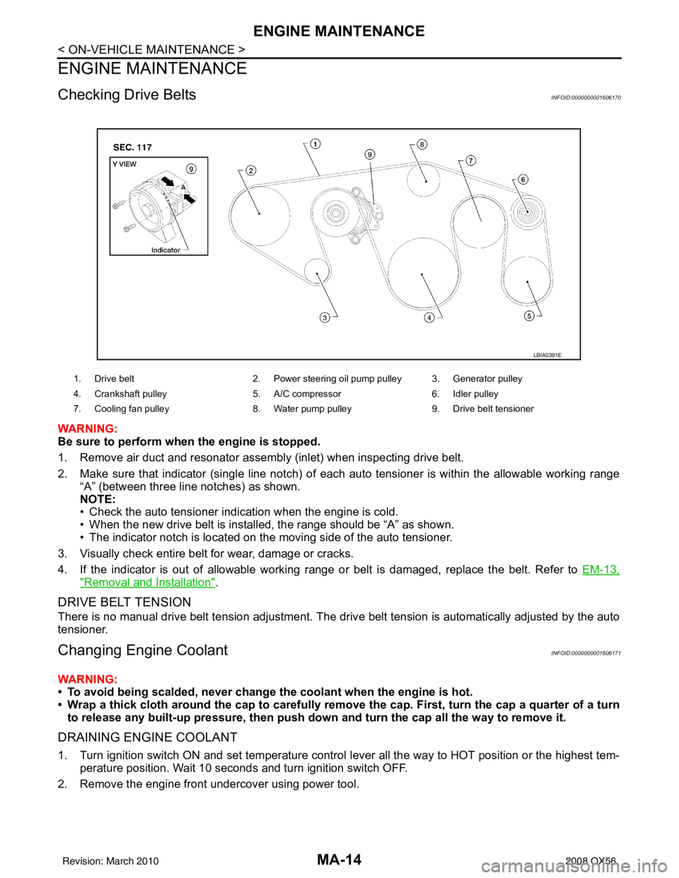
Checking Drive BeltsINFOID:0000000001606170
WARNING:
Be sure to perform when the engine is stopped.
1. Remove air duct and resonator assembly (inlet) when inspecting drive belt.
2. Make sure that indicator (single line notch) of each auto tensioner is within the allowable working range“A” (between three line notches) as shown.
NOTE:
• Check the auto tensioner indication when the engine is cold.
• When the new drive belt is installed, the range should be “A” as shown.
• The indicator notch is located on the moving side of the auto tensioner.
3. Visually check entire belt for wear, damage or cracks.
4. If the indicator is out of allowable working range or belt is damaged, replace the belt. Refer to EM-13,
"Removal and Installation".
DRIVE BELT TENSION
There is no manual drive belt tension adjustment. The driv e belt tension is automatically adjusted by the auto
tensioner.
Changing Engine CoolantINFOID:0000000001606171
WARNING:
• To avoid being scalded, never change the coolant when the engine is hot.
• Wrap a thick cloth around the cap to carefully remove the cap. First, turn the cap a quarter of a turn
to release any built-up pressure, th en push down and turn the cap all the way to remove it.
DRAINING ENGINE COOLANT
1. Turn ignition switch ON and set temperature control lever all the way to HOT position or the highest tem-
perature position. Wait 10 seconds and turn ignition switch OFF.
2. Remove the engine front undercover using power tool.
1. Drive belt 2. Power steering oil pump pulley 3. Generator pulley
4. Crankshaft pulley 5. A/C compressor6. Idler pulley
7. Cooling fan pulley 8. Water pump pulley 9. Drive belt tensioner
LBIA0391E
Revision: March 2010 2008 QX56
Page 2627 of 4083
CHASSIS AND BODY MAINTENANCEMA-29
< ON-VEHICLE MAINTENANCE >
C
DE
F
G H
I
J
K L
M B
MA
N
O A
7. Start balancer machine. Make sure that inner and outer residual imbalance values are 5 g (0.17 oz) each
or below.
8. If either residual imbalance value exceeds 5 g (0.17 oz), repeat installation procedures.
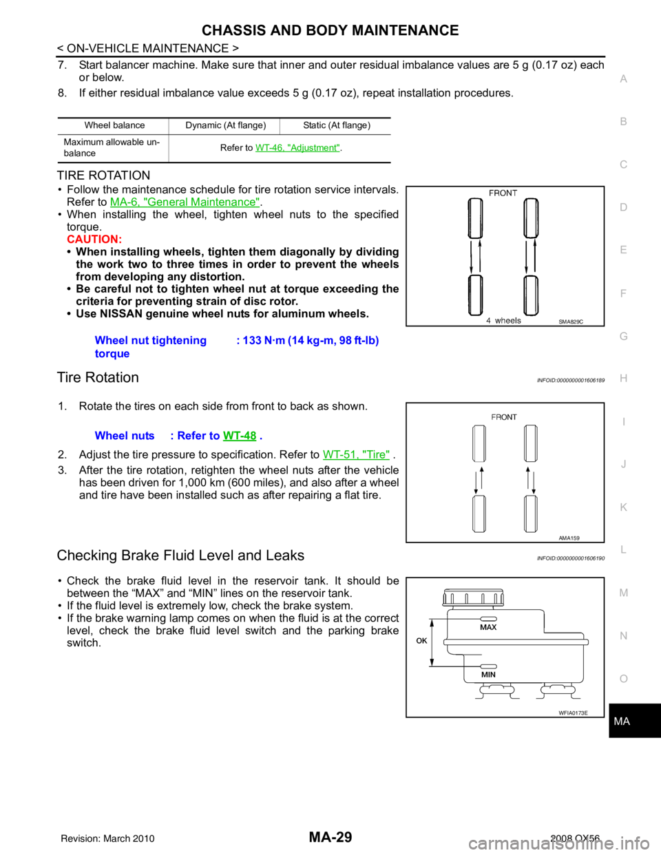
TIRE ROTATION
• Follow the maintenance schedule for tire rotation service intervals.
Refer to MA-6, "
General Maintenance".
• When installing the wheel, tighten wheel nuts to the specified
torque.
CAUTION:
• When installing wheels, tighte n them diagonally by dividing
the work two to three times in order to prevent the wheels
from developing any distortion.
• Be careful not to tighten wh eel nut at torque exceeding the
criteria for preventing strain of disc rotor.
• Use NISSAN genuine wheel nuts for aluminum wheels.
Tire RotationINFOID:0000000001606189
1. Rotate the tires on each side from front to back as shown.
2. Adjust the tire pressure to specification. Refer to WT-51, "
Tire" .
3. After the tire rotation, retighten the wheel nuts after the vehicle has been driven for 1,000 km (600 miles), and also after a wheel
and tire have been installed such as after repairing a flat tire.
Checking Brake Flui d Level and LeaksINFOID:0000000001606190
• Check the brake fluid level in the reservoir tank. It should be
between the “MAX” and “MIN” li nes on the reservoir tank.
• If the fluid level is extremely low, check the brake system.
• If the brake warning lamp comes on when the fluid is at the correct
level, check the brake fluid level switch and the parking brake
switch.
Wheel balance Dynamic (At flange) Static (At flange)
Maximum allowable un-
balance Refer to WT-46, "
Adjustment".
Wheel nut tightening
torque: 133 N·m (14 kg-m, 98 ft-lb)
SMA829C
Wheel nuts : Refer to
WT-48 .
AMA159
WFIA0173E
Revision: March 2010 2008 QX56