Page 3985 of 4083
"TIRE PRESSURE" INFORMATION IN DISPLAY UNIT DOES NOT EXIST
WT-39
< SYMPTOM DIAGNOSIS >
C
D F
G H
I
J
K L
M A
B
WT
N
O P
"TIRE PRESSURE" INFORMATION IN DISPLAY UNIT DOES NOT EXIST
"TIRE PRESSURE" Information in Display Unit Does Not ExistINFOID:0000000001735404
DIAGNOSTIC PROCEDURE
1.SELF-DIAGNOSTIC RESULT CHECK
Using CONSULT-III, check display contents in self-diagnostic results.
Is "CAN COMM CIRCUIT" displayed in the self-diagnosis display items?
YES >> Malfunction in CAN communication system.
NO >> GO TO 2.
2.CHECK DISPLAY UNIT
Perform display unit self-diagnosis. Refer to AV-33, "
AV CONTROL UNIT : CONSULT-III Function".
Inspection results OK?
OK >> Replace BCM. Refer to BCS-55, "Removal and Installation".
NG >> Repair or replace malfunctioning parts.
Revision: March 2010 2008 QX56
Page 3987 of 4083

NOISE, VIBRATION AND HARSHNESS (NVH) TROUBLESHOOTINGWT-41
< SYMPTOM DIAGNOSIS >
C
DF
G H
I
J
K L
M A
B
WT
N
O P
NOISE, VIBRATION AND HARSHN ESS (NVH) TROUBLESHOOTING
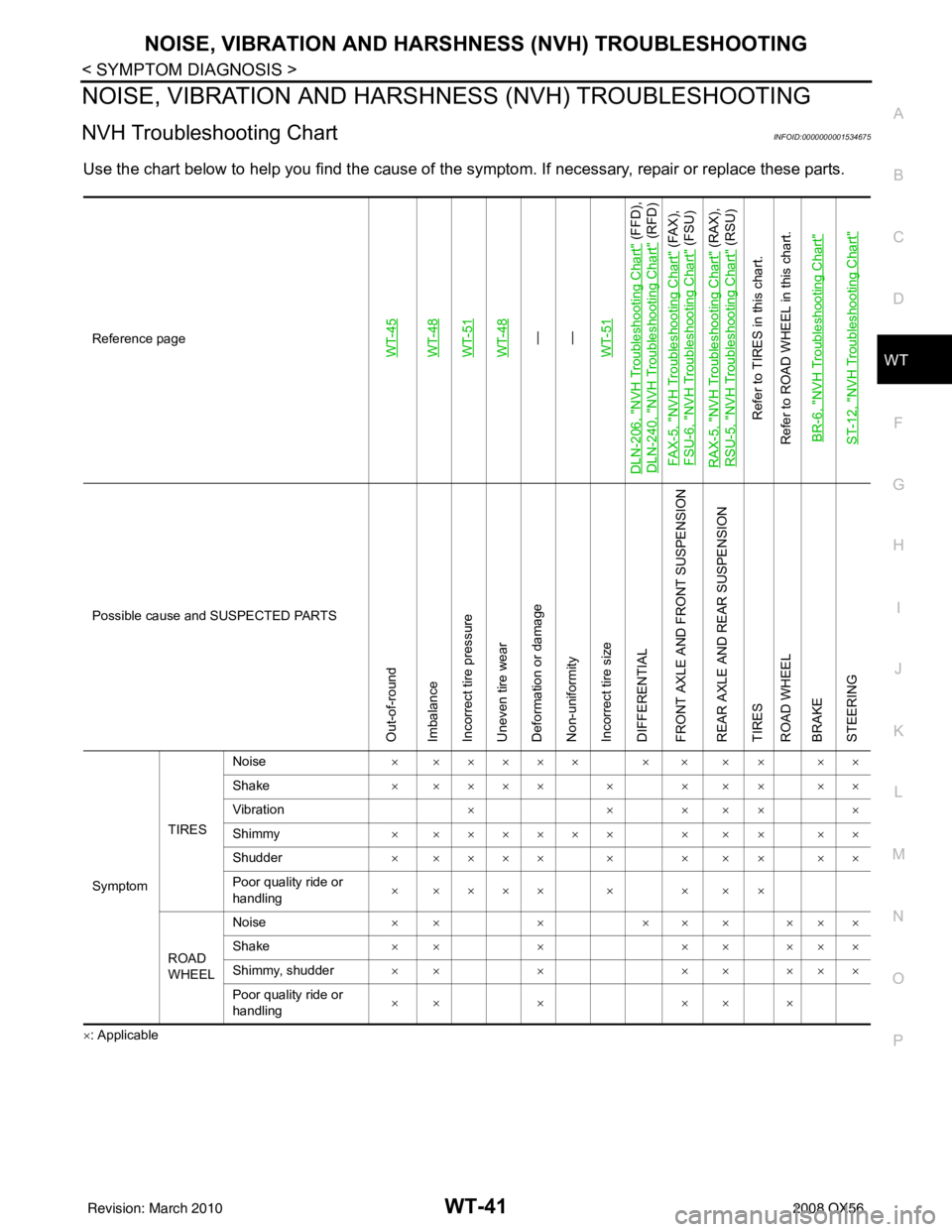
NVH Troubleshooting ChartINFOID:0000000001534675
Use the chart below to help you find t he cause of the symptom. If necessary, repair or replace these parts.
×: ApplicableReference page
WT-45WT-48WT-51WT-48—
—
WT-51
DLN-206, "
NVH Troubleshooting Chart
" (FFD),
DLN-240, "
NVH Troubleshooting Chart
" (RFD)
FAX-5, "
NVH Troubleshooting Chart
" (FAX),
FSU-6, "
NVH Troubleshooting Chart
" (FSU)
RAX-5, "
NVH Troubleshooting Chart
" (RAX),
RSU-5, "
NVH Troubleshooting Chart
" (RSU)
Refer to TIRES in this chart.
Refer to ROAD WHEEL in this chart.
BR-6, "
NVH Troubleshooting Chart
"
ST-12, "
NVH Troubleshooting Chart
"
Possible cause and SUSPECTED PARTS
Out-of-round
Imbalance
Incorrect tire pressure
Uneven tire wear
Deformation or damage
Non-uniformity
Incorrect tire size
DIFFERENTIAL
FRONT AXLE AND FRONT SUSPENSION
REAR AXLE AND REAR SUSPENSION
TIRES
ROAD WHEEL
BRAKE
STEERING
Symptom TIRESNoise
× ××××× × × ×× ××
Shake × ×××× × × ×× ××
Vibration ××× ×××
Shimmy × ×××××× × ×× ××
Shudder × ×××× × × ×× ××
Poor quality ride or
handling × ×××× × × ××
ROAD
WHEEL Noise
×× × ××× ×××
Shake ×× × ×× ×××
Shimmy, shudder ×× × ×× ×××
Poor quality ride or
handling ×× ×
×× ×
Revision: March 2010 2008 QX56
Page 3994 of 4083
WT-48
< ON-VEHICLE REPAIR >
WHEEL AND TIRE ASSEMBLY
Rotation
INFOID:0000000001534678
NOTE:
Follow the maintenance schedule for tire rotation service intervals. Refer to MA-29, "
Tire Rotation" .
1. Rotate the tires on each side from front to back as shown. Do not include the spare tire when rotating the tires.
CAUTION:
When installing wheel s, tighten them diagonally by dividing
the work two to three times in order to prevent the wheels
from developing any distortion.
2. Adjust the tire pressure to specification. Refer to WT-51, "
Tire" .
3. After the tire rotation, retighten the wheel nuts after the vehicle has been driven for 1,000 km (600 miles), and also after every
wheel and tire have been installed such as after repairing a flat tire. Wheel nut torque : 133 N·m (14 kg-m, 98 ft-lb)
SMA829C
Revision: March 2010
2008 QX56
Page 3995 of 4083

REMOVAL AND INSTALLATIONWT-49
< REMOVAL AND INSTALLATION >
C
DF
G H
I
J
K L
M A
B
WT
N
O P
REMOVAL AND INSTALLATION
REMOVAL AND INSTALLATION
Transmitter (Pressure Sensor)INFOID:0000000001534679
REMOVAL
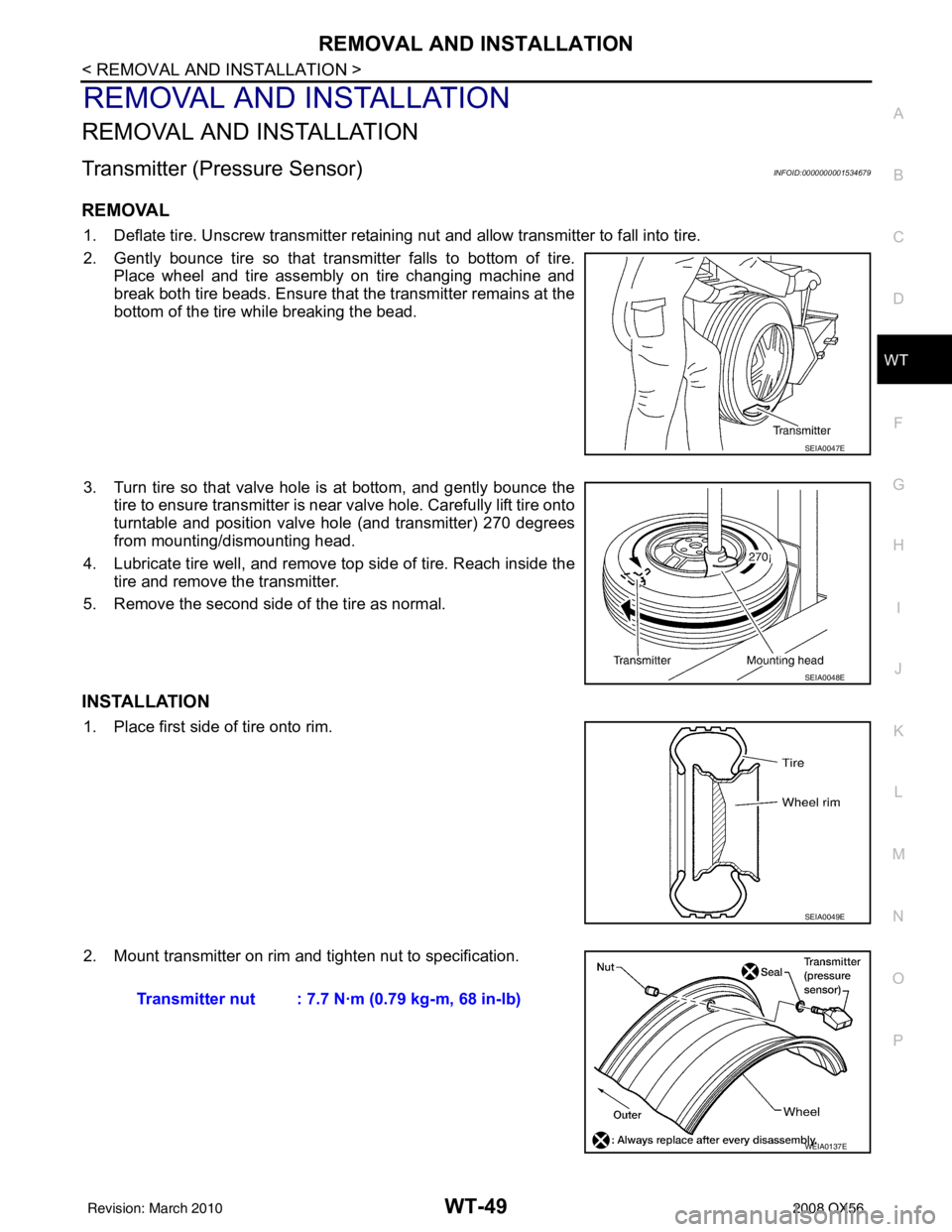
1. Deflate tire. Unscrew transmitter retaining nut and allow transmitter to fall into tire.
2. Gently bounce tire so that transmitter falls to bottom of tire. Place wheel and tire assembly on tire changing machine and
break both tire beads. Ensure that the transmitter remains at the
bottom of the tire while breaking the bead.
3. Turn tire so that valve hole is at bottom, and gently bounce the tire to ensure transmitter is near valve hole. Carefully lift tire onto
turntable and position valve hole (and transmitter) 270 degrees
from mounting/dismounting head.
4. Lubricate tire well, and remove top side of tire. Reach inside the tire and remove the transmitter.
5. Remove the second side of the tire as normal.
INSTALLATION
1. Place first side of tire onto rim.
2. Mount transmitter on rim and tighten nut to specification.
SEIA0047E
SEIA0048E
SEIA0049E
Transmitter nut : 7.7 N·m (0.79 kg-m, 68 in-lb)
WEIA0137E
Revision: March 2010 2008 QX56
Page 3997 of 4083
SERVICE DATA AND SPECIFICATIONS (SDS)WT-51
< SERVICE DATA AND SPECIFICATIONS (SDS)
C
DF
G H
I
J
K L
M A
B
WT
N
O P
SERVICE DATA AND SPECIFICATIONS (SDS)
SERVICE DATA AND SPECIFICATIONS (SDS)
Road WheelINFOID:0000000001534670
TireINFOID:0000000001534671
Unit: kPa (kg/cm2, psi)
Wheel type Aluminum
Maximum radial runout limit Lateral mm (in)
0.3 (0.012) or less
Radial mm (in) 0.3 (0.012) or less
Maximum residual imbalance Dynamic (at rim flange)
Less than 5 g (0.18 oz) (per side)
Static (at rim flange) Less than 10 g (0.35 oz)
Tire size Air pressure
Conventional tire Spare tire
Full size spare tire —240 (2.4, 35)
P275/60R20 240 (2.4, 35)—
Revision: March 2010 2008 QX56
Page 4008 of 4083

DIAGNOSIS SYSTEM (BCM)WW-11
< FUNCTION DIAGNOSIS >
C
DE
F
G H
I
J
K
M A
B
WW
N
O P
DIAGNOSIS SYSTEM (BCM)
COMMON ITEM
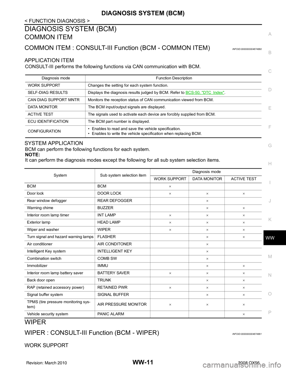
COMMON ITEM : CONSULT-III Fu nction (BCM - COMMON ITEM)INFOID:0000000004874860
APPLICATION ITEM
CONSULT-III performs the following functions via CAN communication with BCM.
SYSTEM APPLICATION
BCM can perform the following functions for each system.
NOTE:
It can perform the diagnosis modes except the following for all sub system selection items.
WIPER
WIPER : CONSULT-III Function (BCM - WIPER)INFOID:0000000004874861
WORK SUPPORT
Diagnosis mode Function Description
WORK SUPPORT Changes the setting for each system function.
SELF-DIAG RESULTS Displays the diagnosis results judged by BCM. Refer to BCS-50, "
DTCIndex".
CAN DIAG SUPPORT MNTR Monitors the reception status of CAN communication viewed from BCM.
DATA MONITOR The BCM input/output signals are displayed.
ACTIVE TEST The signals used to activate each device are forcibly supplied from BCM.
ECU IDENTIFICATION The BCM pa rt number is displayed.
CONFIGURATION • Enables to read and save the vehicle specification.
• Enables to write the vehicle specification when replacing BCM.
System
Sub system selection item Diagnosis mode
WORK SUPPORT DATA MONITOR ACTIVE TEST
BCM BCM ×
Door lock DOOR LOCK ×××
Rear window defogger REAR DEFOGGER ×
Warning chime BUZZER ××
Interior room lamp timer INT LAMP ×××
Exterior lamp HEAD LAMP ×××
Wiper and washer WIPER ×××
Turn signal and hazard warning lamps FLASHER ××
Air conditioner AIR CONDITONER ×
Intelligent Key system INTELLIGENT KEY ×
Combination switch COMB SW ×
Immobilizer IMMU ××
Interior room lamp battery saver BATTERY SAVER ×××
Back door open TRUNK ××
RAP (retained accessory power) RETAINED PWR ×××
Signal buffer system SIGNAL BUFFER ××
TPMS (tire pressure monitoring sys-
tem) AIR PRESSURE MONITOR
×××
Vehicle security system PANIC ALARM ×
Revision: March 2010 2008 QX56
Page 4041 of 4083

WW-44
< ECU DIAGNOSIS >
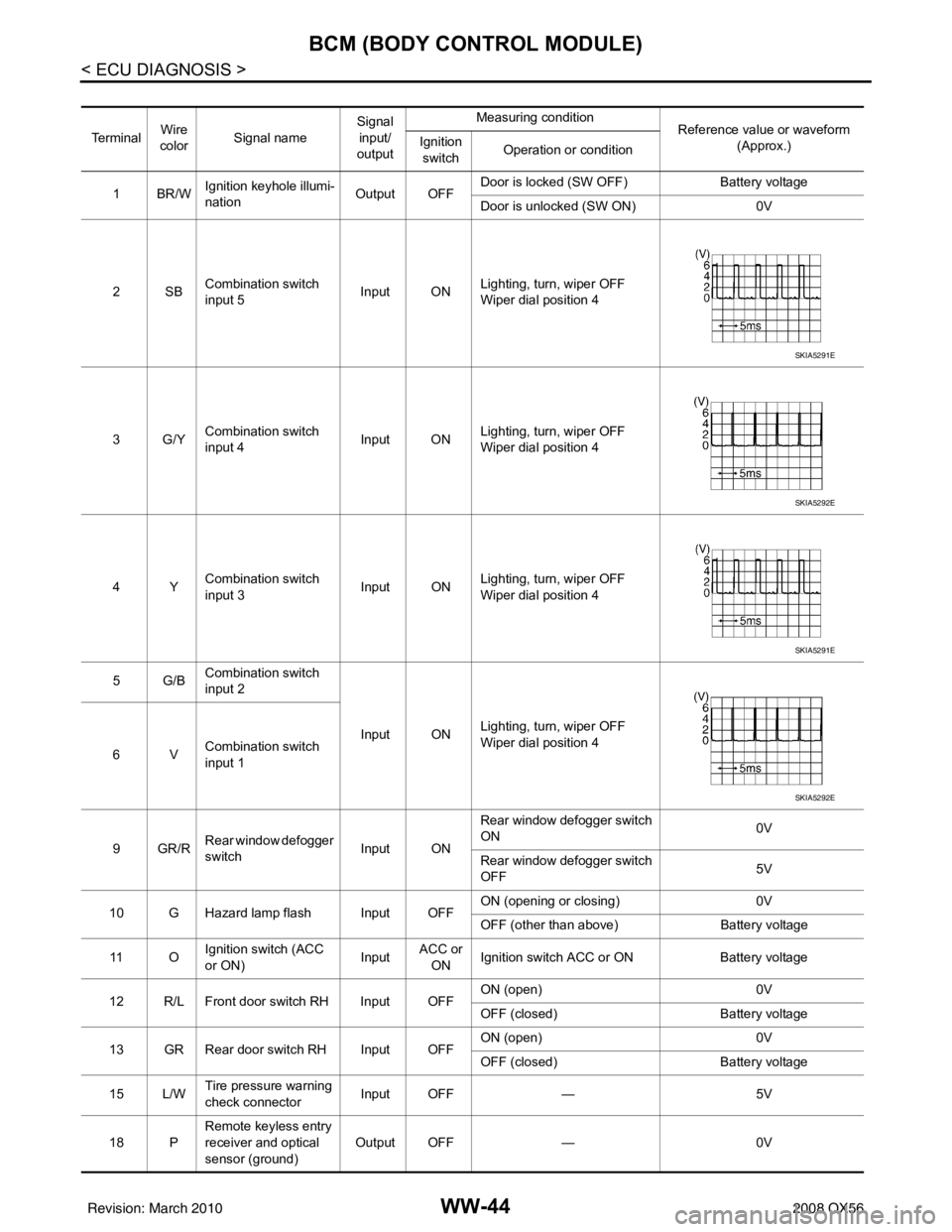
BCM (BODY CONTROL MODULE)
Te r m i n a lWire
color Signal name Signal
input/
output Measuring condition
Reference value or waveform
(Approx.)
Ignition
switch Operation or condition
1BR/W Ignition keyhole illumi-
nation Output OFFDoor is locked (SW OFF)
Battery voltage
Door is unlocked (SW ON) 0V
2SB Combination switch
input 5 Input ON
Lighting, turn, wiper OFF
Wiper dial position 4
3G/Y Combination switch
input 4 Input ONLighting, turn, wiper OFF
Wiper dial position 4
4Y Combination switch
input 3 Input ON
Lighting, turn, wiper OFF
Wiper dial position 4
5G/B Combination switch
input 2
Input ONLighting, turn, wiper OFF
Wiper dial position 4
6V Combination switch
input 1
9GR/R Rear window defogger
switch
Input ONRear window defogger switch
ON
0V
Rear window defogger switch
OFF 5V
10 G Hazard lamp flash Input OFF ON (opening or closing)
0V
OFF (other than above) Battery voltage
11 O Ignition switch (ACC
or ON)
InputACC or
ON Ignition switch ACC or ON
Battery voltage
12 R/L Front door switch RH Input OFF ON (open)
0V
OFF (closed) Battery voltage
13 GR Rear door switch RH Input OFF ON (open)
0V
OFF (closed) Battery voltage
15 L/W Tire pressure warning
check connector
Input OFF
—5V
18 P Remote keyless entry
receiver and optical
sensor (ground)
Output OFF
—0V
SKIA5291E
SKIA5292E
SKIA5291E
SKIA5292E
Revision: March 2010 2008 QX56
Page 4051 of 4083

WW-54
< ECU DIAGNOSIS >
BCM (BODY CONTROL MODULE)
CONSULT displayFail-safeIntelligent Key
warning lamp ON Tire pressure
monitor warning lamp ON Reference page
No DTC is detected.
further testing
may be required. ————
U1000: CAN COMM CIRCUIT ———BCS-30
U1010: CONTROL UNIT (CAN) ———BCS-31
B2190: NATS ANTENNA AMP ———SEC-29
B2191: DIFFERENCE OF KEY ———SEC-32
B2192: ID DISCORD BCM-ECM ———SEC-33
B2193: CHAIN OF BCM-ECM ———SEC-35
B2552: INTELLIGENT KEY ———SEC-37
B2590: NATS MALFUNCTION ———SEC-38
C1704: LOW PRESSURE FL ———WT-31
C1705: LOW PRESSURE FR ———WT-31
C1706: LOW PRESSURE RR ———WT-31
C1707: LOW PRESSURE RL ———WT-31
C1708: [NO DATA] FL ———WT-14
C1709: [NO DATA] FR ———WT-14
C1710: [NO DATA] RR ———WT-14
C1711: [NO DATA] RL ———WT-14
C1712: [CHECKSUM ERR] FL ———WT-16
C1713: [CHECKSUM ERR] FR ———WT-16
C1714: [CHECKSUM ERR] RR ———WT-16
C1715: [CHECKSUM ERR] RL ———WT-16
C1716: [PRESSDATA ERR] FL ———WT-18
C1717: [PRESSDATA ERR] FR ———WT-18
C1718: [PRESSDATA ERR] RR ———WT-18
C1719: [PRESSDATA ERR] RL ———WT-18
C1720: [CODE ERR] FL ———WT-16
C1721: [CODE ERR] FR ———WT-16
C1722: [CODE ERR] RR ———WT-16
C1723: [CODE ERR] RL ———WT-16
C1724: [BATT VOLT LOW] FL ———WT-16
C1725: [BATT VOLT LOW] FR ———WT-16
C1726: [BATT VOLT LOW] RR ———WT-16
C1727: [BATT VOLT LOW] RL ———WT-16
C1729: VHCL SPEED SIG ERR ———WT-19
C1735: IGNITION SIGNAL ———WT-20
Revision: March 2010 2008 QX56