Page 3966 of 4083
WT-20
< COMPONENT DIAGNOSIS >
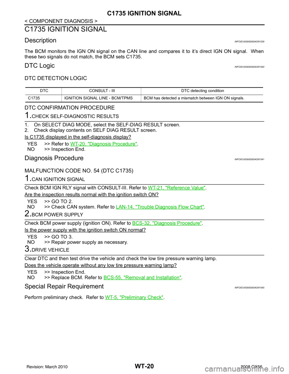
C1735 IGNITION SIGNAL
C1735 IGNITION SIGNAL
DescriptionINFOID:0000000004291539
The BCM monitors the IGN ON signal on the CAN line and compares it to it’s direct IGN ON signal. When
these two signals do not match, the BCM sets C1735.
DTC LogicINFOID:0000000004291540
DTC DETECTION LOGIC
DTC CONFIRMATION PROCEDURE
1.CHECK SELF-DIAGNOSTIC RESULTS
1. On SELECT DIAG MODE, select the SELF-DIAG RESULT screen.
2. Check display contents on SELF DIAG RESULT screen.
Is C1735 displayed in the self-diagnosis display?
YES >> Refer to WT-20, "Diagnosis Procedure".
NO >> Inspection End.
Diagnosis ProcedureINFOID:0000000004291541
MALFUNCTION CODE NO. 54 (DTC C1735)
1.CAN IGNITION SIGNAL
Check BCM IGN RLY signal with CONSULT-III. Refer to WT-21, "
Reference Value".
Are the inspection results normal with the ignition switch ON?
YES >> GO TO 2.
NO >> Check CAN system. Refer to LAN-14, "
Trouble Diagnosis Flow Chart".
2.BCM POWER SUPPLY
Check BCM power supply (ignition ON). Refer to BCS-32, "
Diagnosis Procedure".
Is the power supply with the ignition switch ON normal?
YES >> GO TO 3.
NO >> Repair power supply as necessary.
3.DRIVE VEHICLE
Clear DTC and then test drive the vehicle and check the low tire pressure warning lamp.
Does the vehicle operate without any low tire pressure warning lamp?
YES >> Inspection End.
NO >> Replace BCM. Refer to BCS-55, "
Removal and Installation".
Special Repair RequirementINFOID:0000000004291545
Perform preliminary check. Refer to WT-5, "Preliminary Check".
DTCCONSULT - III DTC detecting condition
C1735 IGNITION SIGNAL LINE - BCM/TPMS BCM has detected a mismatch between IGN ON signals.
Revision: March 2010 2008 QX56
Page 3970 of 4083
WT-24
< ECU DIAGNOSIS >
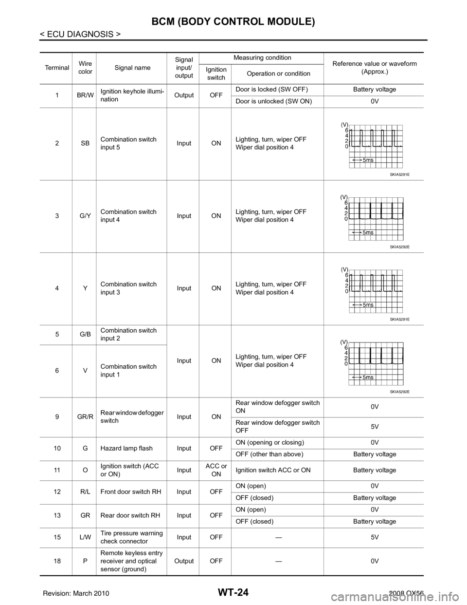
BCM (BODY CONTROL MODULE)
Te r m i n a lWire
color Signal name Signal
input/
output Measuring condition
Reference value or waveform
(Approx.)
Ignition
switch Operation or condition
1BR/W Ignition keyhole illumi-
nation Output OFFDoor is locked (SW OFF)
Battery voltage
Door is unlocked (SW ON) 0V
2SB Combination switch
input 5 Input ON
Lighting, turn, wiper OFF
Wiper dial position 4
3G/Y Combination switch
input 4 Input ONLighting, turn, wiper OFF
Wiper dial position 4
4Y Combination switch
input 3 Input ON
Lighting, turn, wiper OFF
Wiper dial position 4
5G/B Combination switch
input 2
Input ONLighting, turn, wiper OFF
Wiper dial position 4
6V Combination switch
input 1
9GR/R Rear window defogger
switch
Input ONRear window defogger switch
ON
0V
Rear window defogger switch
OFF 5V
10 G Hazard lamp flash Input OFF ON (opening or closing)
0V
OFF (other than above) Battery voltage
11 O Ignition switch (ACC
or ON)
InputACC or
ON Ignition switch ACC or ON
Battery voltage
12 R/L Front door switch RH Input OFF ON (open)
0V
OFF (closed) Battery voltage
13 GR Rear door switch RH Input OFF ON (open)
0V
OFF (closed) Battery voltage
15 L/W Tire pressure warning
check connector
Input OFF
—5V
18 P Remote keyless entry
receiver and optical
sensor (ground)
Output OFF
—0V
SKIA5291E
SKIA5292E
SKIA5291E
SKIA5292E
Revision: March 2010 2008 QX56
Page 3978 of 4083
WT-32
< ECU DIAGNOSIS >
BCM (BODY CONTROL MODULE)
NOTE:
Before performing the self-diagnosis, be sure to register the ID or else the actual malfunction location may be different from that dis-
played on CONSULT-III.
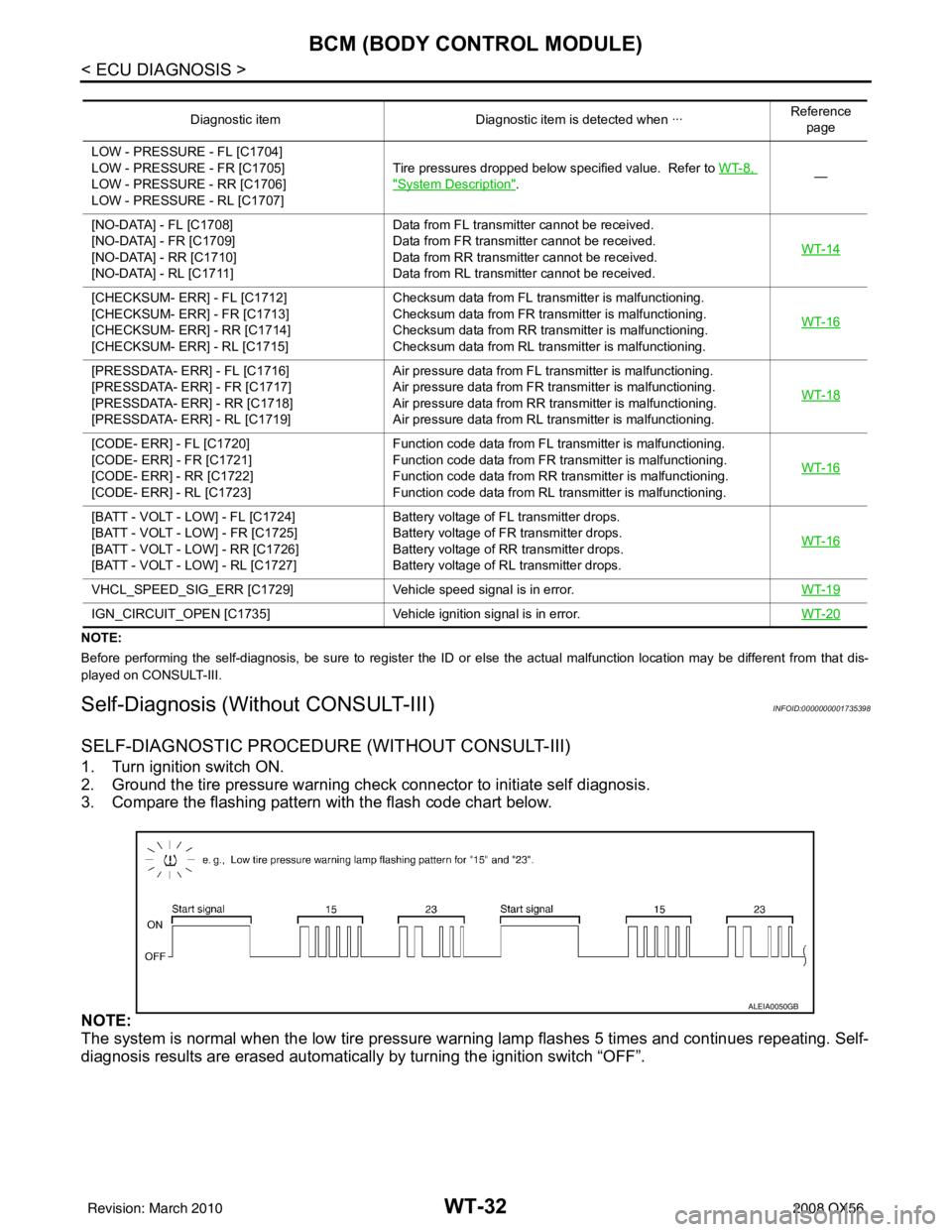
Self-Diagnosis (Without CONSULT-III)INFOID:0000000001735398
SELF-DIAGNOSTIC PROCEDURE (WITHOUT CONSULT-III)
1. Turn ignition switch ON.
2. Ground the tire pressure warning check connector to initiate self diagnosis.
3. Compare the flashing pattern with the flash code chart below.
NOTE:
The system is normal when the low tire pressure warning lamp flashes 5 times and continues repeating. Self-
diagnosis results are erased automatically by turning the ignition switch “OFF”.
Diagnostic item Diagnostic item is detected when ··· Reference
page
LOW - PRESSURE - FL [C1704]
LOW - PRESSURE - FR [C1705]
LOW - PRESSURE - RR [C1706]
LOW - PRESSURE - RL [C1707] Tire pressures dropped below specified value. Refer to WT-8,
"System Description".
—
[NO-DATA] - FL [C1708]
[NO-DATA] - FR [C1709]
[NO-DATA] - RR [C1710]
[NO-DATA] - RL [C1711] Data from FL transmitter cannot be received.
Data from FR transmitter cannot be received.
Data from RR transmitter cannot be received.
Data from RL transmitter cannot be received.
WT-14
[CHECKSUM- ERR] - FL [C1712]
[CHECKSUM- ERR] - FR [C1713]
[CHECKSUM- ERR] - RR [C1714]
[CHECKSUM- ERR] - RL [C1715]Checksum data from FL transmitter is malfunctioning.
Checksum data from FR transmitter is malfunctioning.
Checksum data from RR transmitter is malfunctioning.
Checksum data from RL transmitter is malfunctioning.
WT-16
[PRESSDATA- ERR] - FL [C1716]
[PRESSDATA- ERR] - FR [C1717]
[PRESSDATA- ERR] - RR [C1718]
[PRESSDATA- ERR] - RL [C1719]Air pressure data from FL transmitter is malfunctioning.
Air pressure data from FR transmitter is malfunctioning.
Air pressure data from RR transmitter is malfunctioning.
Air pressure data from RL transmitter is malfunctioning.
WT-18
[CODE- ERR] - FL [C1720]
[CODE- ERR] - FR [C1721]
[CODE- ERR] - RR [C1722]
[CODE- ERR] - RL [C1723]Function code data from FL transmitter is malfunctioning.
Function code data from FR transmitter is malfunctioning.
Function code data from RR transmitter is malfunctioning.
Function code data from RL transmitter is malfunctioning.
WT-16
[BATT - VOLT - LOW] - FL [C1724]
[BATT - VOLT - LOW] - FR [C1725]
[BATT - VOLT - LOW] - RR [C1726]
[BATT - VOLT - LOW] - RL [C1727]Battery voltage of FL transmitter drops.
Battery voltage of FR transmitter drops.
Battery voltage of RR transmitter drops.
Battery voltage of RL transmitter drops.
WT-16
VHCL_SPEED_SIG_ERR [C1729]
Vehicle speed signal is in error. WT-19
IGN_CIRCUIT_OPEN [C1735]Vehicle ignition signal is in error. WT-20
ALEIA0050GB
Revision: March 2010 2008 QX56
Page 3979 of 4083
BCM (BODY CONTROL MODULE)WT-33
< ECU DIAGNOSIS >
C
DF
G H
I
J
K L
M A
B
WT
N
O P
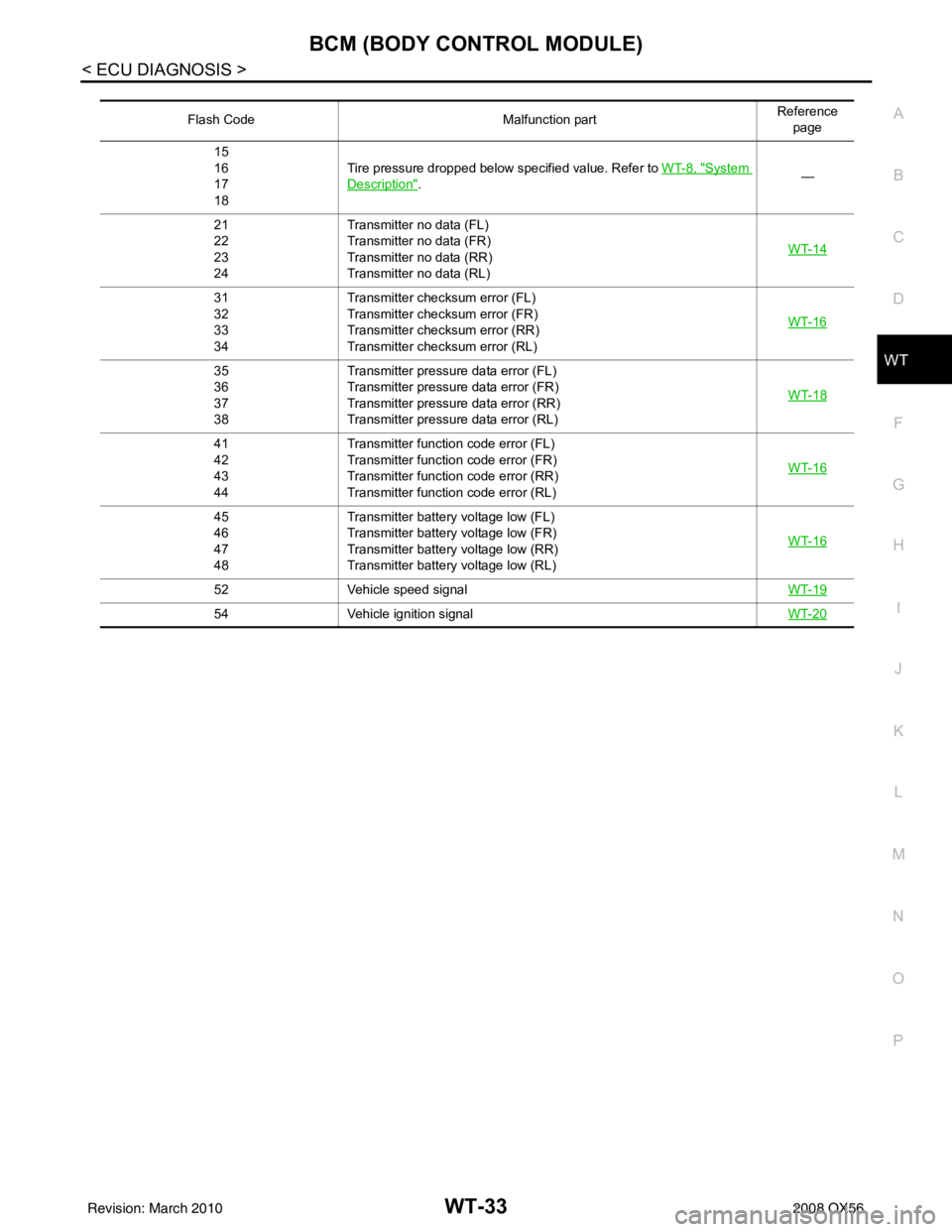
Flash Code Malfunction partReference
page
15
16
17
18 Tire pressure dropped below specified value. Refer to
WT-8, "
System
Description". —
21
22
23
24 Transmitter no data (FL)
Transmitter no data (FR)
Transmitter no data (RR)
Transmitter no data (RL)
WT-14
31
32
33
34Transmitter chec
ksum error (FL)
Transmitter chec ksum error (FR)
Transmitter chec ksum error (RR)
Transmitter chec ksum error (RL) WT-16
35
36
37
38Transmitter pressure data error (FL)
Transmitter pressure data error (FR)
Transmitter pressure data error (RR)
Transmitter pressure data error (RL)
WT-18
41
42
43
44Transmitter function
code error (FL)
Transmitter function code error (FR)
Transmitter function code error (RR)
Transmitter function code error (RL) WT-16
45
46
47
48Transmitter battery voltage low (FL)
Transmitter battery voltage low (FR)
Transmitter battery voltage low (RR)
Transmitter battery voltage low (RL)
WT-16
52
Vehicle speed signal WT-19
54Vehicle ignition signal WT-20
Revision: March 2010 2008 QX56
Page 3980 of 4083
WT-34
< SYMPTOM DIAGNOSIS >
TPMS
SYMPTOM DIAGNOSIS
TPMS
Symptom TableINFOID:0000000001735399
SymptomReference
Low tire pressure warning lamp does not come on when ignition switch is turned on. WT-35
Low tire pressure warning lamp stays on when ignition switch is turned on.WT-36
Low tire pressure warning lamp flashes when ignition switch is turned on.WT-37
Hazard warning lamps flash when ignition switch is turned on.WT-38
Tire pressure information in display unit does not exist.WT-40
ID registration cannot be completed.WT-40
Revision: March 20102008 QX56
Page 3981 of 4083
LOW TIRE PRESSURE WARNING LAMP DOES NOT TURN ON
WT-35
< SYMPTOM DIAGNOSIS >
C
D F
G H
I
J
K L
M A
B
WT
N
O P
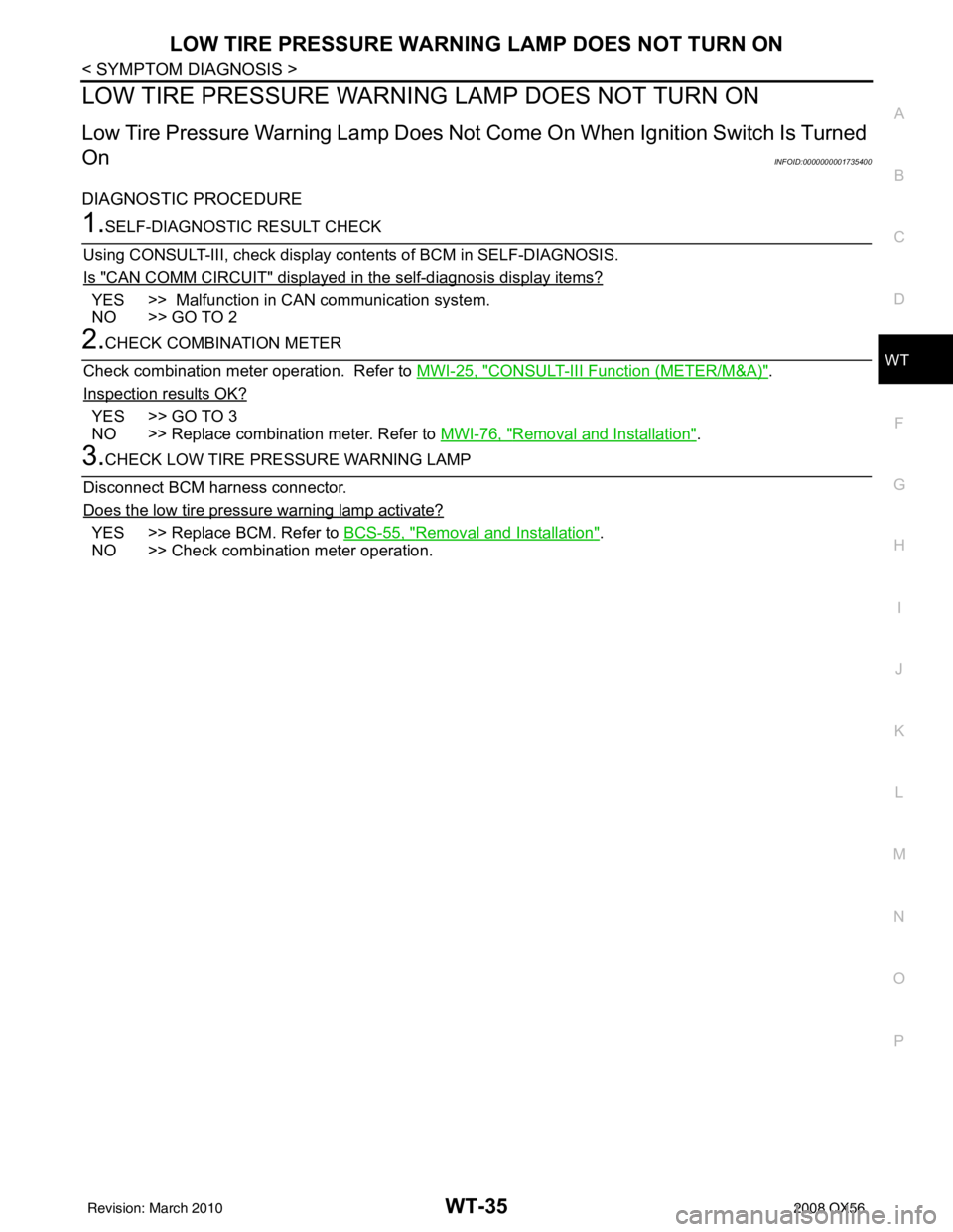
LOW TIRE PRESSURE WARNIN G LAMP DOES NOT TURN ON
Low Tire Pressure Warning Lamp Does Not Come On When Ignition Switch Is Turned
On
INFOID:0000000001735400
DIAGNOSTIC PROCEDURE
1.SELF-DIAGNOSTIC RESULT CHECK
Using CONSULT-III, check display contents of BCM in SELF-DIAGNOSIS.
Is "CAN COMM CIRCUIT" displayed in the self-diagnosis display items?
YES >> Malfunction in CAN communication system.
NO >> GO TO 2
2.CHECK COMBINATION METER
Check combination meter operation. Refer to MWI-25, "
CONSULT-III Function (METER/M&A)".
Inspection results OK?
YES >> GO TO 3
NO >> Replace combination meter. Refer to MWI-76, "
Removal and Installation".
3.CHECK LOW TIRE PRE SSURE WARNING LAMP
Disconnect BCM harness connector.
Does the low tire pressure warning lamp activate?
YES >> Replace BCM. Refer to BCS-55, "Removal and Installation".
NO >> Check combination meter operation.
Revision: March 2010 2008 QX56
Page 3982 of 4083
WT-36
< SYMPTOM DIAGNOSIS >
LOW TIRE PRESSURE WARNING LAMP STAYS ON
LOW TIRE PRESSURE WARNING LAMP STAYS ON
Low Tire Pressure Warning Lamp Stays On When Ignition Switch Is Turned On
INFOID:0000000001735401
DIAGNOSTIC PROCEDURE
1.BCM CONNECTORS
1. Turn ignition switch OFF.
2. Disconnect BCM harness connectors.
3. Check terminals for damage or loose connections.
Are any of the BCM connectors loose or damaged?
YES >> Repair or replace damaged parts.
NO >> GO TO 2
2.BCM POWER SUPPLY AND GROUND CIRCUITS
Check BCM power supply and ground circuits. Refer to BCS-32, "
Diagnosis Procedure".
Are the BCM power supply and ground circuits OK?
YES >> Replace BCM. Refer to BCS-55, "Removal and Installation".
NO >> Repair BCM circuits.
Revision: March 2010 2008 QX56
Page 3983 of 4083
LOW TIRE PRESSURE WARNING LAMP BLINKSWT-37
< SYMPTOM DIAGNOSIS >
C
DF
G H
I
J
K L
M A
B
WT
N
O P
LOW TIRE PRESSURE WA RNING LAMP BLINKS
Low Tire Pressure Warning Lamp Flas hes When Ignition Switch Is Turned On
INFOID:0000000001735402
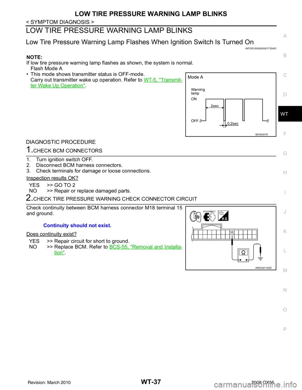
NOTE:
If low tire pressure warning lamp fl ashes as shown, the system is normal.
Flash Mode A
• This mode shows transmitter status is OFF-mode.
Carry out transmitter wake up operation. Refer to WT-5, "
Transmit-
ter Wake Up Operation".
DIAGNOSTIC PROCEDURE
1.CHECK BCM CONNECTORS
1. Turn ignition switch OFF.
2. Disconnect BCM harness connectors.
3. Check terminals for damage or loose connections.
Inspection results OK?
YES >> GO TO 2
NO >> Repair or replace damaged parts.
2.CHECK TIRE PRESSURE WARNING CHECK CONNECTOR CIRCUIT
Check continuity between BCM harness connector M18 terminal 15
and ground.
Does continuity exist?
YES >> Repair circuit for short to ground.
NO >> Replace BCM. Refer to BCS-55, "
Removal and Installa-
tion".
SEIA0347E
Continuity should not exist.
AWEIA0116ZZ
Revision: March 2010 2008 QX56