2008 INFINITI QX56 trailer
[x] Cancel search: trailerPage 161 of 4083

BCM (BODY CONTROL MODULE)ADP-147
< ECU DIAGNOSIS >
C
DE
F
G H
I
K L
M A
B
ADP
N
O P
44 O Rear wiper auto stop
switch 1 Input ONRise up position (rear wiper
arm on stopper)
0V
A Position (full clockwise stop
position) Battery voltage
Forward sweep (counterclock-
wise direction) Fluctuating
B Position (full counterclock-
wise stop position) 0V
Reverse sweep (clockwise di-
rection) Fluctuating
47 SB Front door switch LH Input OFF ON (open)
0V
OFF (closed) Battery voltage
48 R/Y Rear door switch LH Input OFF ON (open)
0V
OFF (closed) Battery voltage
49 R Cargo lamp Output OFFAny door open (ON)
0V
All doors closed (OFF) Battery voltage
51 G/Y Trailer turn signal
(right) Output ON Turn right ON
52 G/B Trailer turn signal (left) Output ON Turn left ON
53 L/W Glass hatch lock actu-
ator
Output OFFGlass hatch switch released
0
Glass hatch switch pressed Battery
54 Y Rear wiper output cir-
cuit 2 Input ONRise up position (rear wiper
arm on stopper)
0V
A Position (full clockwise stop
position) 0V
Forward sweep (counterclock-
wise direction) 0V
B Position (full counterclock-
wise stop position) Battery voltage
Reverse sweep (clockwise di-
rection) Battery voltage
55 SB Rear wiper output cir-
cuit 1 Output ONOFF
0
ON Battery voltage
56 R/G Battery saver output Output OFF
30 minutes after ignition
switch is turned OFF 0V
ON — Battery voltage
57 Y/R Battery power supply Input OFF —Battery voltage
Te r m i n a l
Wire
color Signal name Signal
input/
output Measuring condition
Reference value or waveform
(Approx.)
Ignition
switch Operation or condition
SKIA3009J
SKIA3009J
Revision: March 2010
2008 QX56
Page 409 of 4083
![INFINITI QX56 2008 Factory Service Manual BCS-44
< ECU DIAGNOSIS >[BCM]
BCM (BODY CONTROL MODULE)
44 ORear wiper auto stop
switch 1 Input ONRise up position (rear wiper
arm on stopper)
0V
A Position (full clockwise stop
position) Battery v INFINITI QX56 2008 Factory Service Manual BCS-44
< ECU DIAGNOSIS >[BCM]
BCM (BODY CONTROL MODULE)
44 ORear wiper auto stop
switch 1 Input ONRise up position (rear wiper
arm on stopper)
0V
A Position (full clockwise stop
position) Battery v](/manual-img/42/57030/w960_57030-408.png)
BCS-44
< ECU DIAGNOSIS >[BCM]
BCM (BODY CONTROL MODULE)
44 ORear wiper auto stop
switch 1 Input ONRise up position (rear wiper
arm on stopper)
0V
A Position (full clockwise stop
position) Battery voltage
Forward sweep (counterclock-
wise direction) Fluctuating
B Position (full counterclock-
wise stop position) 0V
Reverse sweep (clockwise di-
rection) Fluctuating
47 SB Front door switch LH Input OFF ON (open)
0V
OFF (closed) Battery voltage
48 R/Y Rear door switch LH Input OFF ON (open)
0V
OFF (closed) Battery voltage
49 R Cargo lamp Output OFFAny door open (ON)
0V
All doors closed (OFF) Battery voltage
51 G/Y Trailer turn signal
(right) Output ON Turn right ON
52 G/B Trailer turn signal (l eft) Output ON Turn left ON
53 L/W Glass hatch lock actu-
ator
Output OFFGlass hatch switch released
0
Glass hatch switch pressed Battery
54 Y Rear wiper output cir-
cuit 2 Input ONRise up position (rear wiper
arm on stopper)
0V
A Position (full clockwise stop
position) 0V
Forward sweep (counterclock-
wise direction) 0V
B Position (full counterclock-
wise stop position) Battery voltage
Reverse sweep (clockwise di-
rection) Battery voltage
55 SB Rear wiper output cir-
cuit 1 Output ONOFF
0
ON Battery voltage
56 R/G Battery saver output Output OFF
30 minutes after ignition
switch is turned OFF 0V
ON — Battery voltage
57 Y/R Battery power supply Input OFF —Battery voltage
Te r m i n a l
Wire
color Signal name Signal
input/
output Measuring condition
Reference value or waveform
(Approx.)
Ignition
switch Operation or condition
SKIA3009J
SKIA3009J
Revision: March 2010
2008 QX56
Page 706 of 4083

CCS-66
< SYMPTOM DIAGNOSIS >
NORMAL OPERATING CONDITION
NORMAL OPERATING CONDITION
DescriptionINFOID:0000000001731913
PRECAUTIONS FOR VEHICLE-TO-VEHICLE DISTANCE CONTROL MODE
• Intelligent Cruise Control is functionally limited. This never support careless driving and low visibility (rain,fog, etc.). Drive the vehicle safely. Keep a safe di stance between vehicles by decreasing the vehicle speed
according to the driving condition etc.
• Intelligent Cruise Control never stop the vehicle autom atically. Intelligent Cruise Control is automatically
released, and the buzzer sounds if any vehicle ahead is not detected when the vehicle speed is approxi-
mately 35 km (21.5 MPH) or less.
• Use this system when the vehicle speed does not extr emely change. This system may not properly function
when any vehicle cuts in, or when the vehicle ahead s uddenly applies the brake. Then, the warning (buzzer
and indication) activates.
• Never use Intelligent Cruise Control in the following conditions.
- A well-trafficed road, and a tight turn. It may cause any accident because the dr iving does not fit to the road condition.
- A slippery road (e.g., freezing, or snowy road) The vehicle may lose the control by wheelspin.
- The vehicle drives in bad whet her (rain, fog, snow etc.).
The distance from the vehicle ahead is not detected pr ecisely if the whether condition is bad. Intelligent
Cruise Control is released automatically if the wiper activates in low or high speed.
- The vehicle receives bright light (sunshine etc.). The distance from the vehicle ahead is not detected pr ecisely if bright light enters in the vehicle.
- Raindrop or snow is on the sensor.
The distance from the vehicle ahead is not detected prec isely if raindrop or snow attaches on the sensor.
- A steep downhill The setting vehicle speed may exceed if Intelligent Cruise Control does not detect the vehicle ahead. The
brake may heat up in the vehicle- to-vehicle distance control mode.
- A repeated uphill and downhill Intelligent Cruise Control may not detect the vehicl e ahead precisely. An accident may occur by tailgating.
- Maintaining proper vehicle distance is difficult due to frequent acceleration/deceleration. It may cause any accident because the driving does not fit to the road condition if keeping a proper vehicle-
to-vehicle distance is difficult.
- When entering in the highway interchange (swerving off the main line),
Unexpected accident may cause if the vehicle ahead drives slower
than the preset vehicle speed. T he vehicle-to-vehicle distance con-
trol mode accelerates automatically because the vehicle ahead is
not detected on the lane if the own vehicle or the vehicle ahead
changes the lane.
• Intelligent Cruise Control does not activate to the parking vehicles, and vehicles driving extremely slow er than the own vehicle. Never
hit the vehicle stopping at a tollgate, or the tail end of traffic jam.
• Intelligent Cruise Control does not activate to the vehicle edging way, and non-vehicle objects (passengers etc.).
• This function detects the reflector of the vehicle ahead. Intelligent Cruise Control may not detect the vehicle
ahead, and keep a proper vehicle-to-vehicle distance in t he following conditions. Drive the vehicle according
to the driving condition.
- The vehicle ahead installs the reflector higher (trailer etc.).
- The rear of the vehicle ahead is extremely dirt.
- The vehicle ahead or vehicle on other lanes splashes water or snow on the road.
- The vehicle ahead provides dark exhaust gas. Smoke blocks the visibility.
- The vehicle ahead attaches film on the reflector. The v ehicle ahead does not install the reflector. The reflec-
tor is broken.
- Extremely heavy load is on the rear seat or in the cargo area.
- The vehicle drives on a repeated uphill and downhill
EL-2980D
Revision: March 2010 2008 QX56
Page 941 of 4083
![INFINITI QX56 2008 Factory Service Manual DLK-148
< ECU DIAGNOSIS >[WITH INTELLIGENT KEY SYSTEM]
BCM (BODY CONTROL MODULE)
44 ORear wiper auto stop
switch 1 Input ONRise up position (rear wiper
arm on stopper)
0V
A Position (full clockwise INFINITI QX56 2008 Factory Service Manual DLK-148
< ECU DIAGNOSIS >[WITH INTELLIGENT KEY SYSTEM]
BCM (BODY CONTROL MODULE)
44 ORear wiper auto stop
switch 1 Input ONRise up position (rear wiper
arm on stopper)
0V
A Position (full clockwise](/manual-img/42/57030/w960_57030-940.png)
DLK-148
< ECU DIAGNOSIS >[WITH INTELLIGENT KEY SYSTEM]
BCM (BODY CONTROL MODULE)
44 ORear wiper auto stop
switch 1 Input ONRise up position (rear wiper
arm on stopper)
0V
A Position (full clockwise stop
position) Battery voltage
Forward sweep (counterclock-
wise direction) Fluctuating
B Position (full counterclock-
wise stop position) 0V
Reverse sweep (clockwise di-
rection) Fluctuating
47 SB Front door switch LH Input OFF ON (open)
0V
OFF (closed) Battery voltage
48 R/Y Rear door switch LH Input OFF ON (open)
0V
OFF (closed) Battery voltage
49 R Cargo lamp Output OFFAny door open (ON)
0V
All doors closed (OFF) Battery voltage
51 G/Y Trailer turn signal
(right) Output ON Turn right ON
52 G/B Trailer turn signal (l eft) Output ON Turn left ON
53 L/W Glass hatch lock actu-
ator
Output OFFGlass hatch switch released
0
Glass hatch switch pressed Battery
54 Y Rear wiper output cir-
cuit 2 Input ONRise up position (rear wiper
arm on stopper)
0V
A Position (full clockwise stop
position) 0V
Forward sweep (counterclock-
wise direction) 0V
B Position (full counterclock-
wise stop position) Battery voltage
Reverse sweep (clockwise di-
rection) Battery voltage
55 SB Rear wiper output cir-
cuit 1 Output ONOFF
0
ON Battery voltage
56 R/G Battery saver output Output OFF
30 minutes after ignition
switch is turned OFF 0V
ON — Battery voltage
57 Y/R Battery power supply Input OFF —Battery voltage
Te r m i n a l
Wire
color Signal name Signal
input/
output Measuring condition
Reference value or waveform
(Approx.)
Ignition
switch Operation or condition
SKIA3009J
SKIA3009J
Revision: March 2010
2008 QX56
Page 1929 of 4083

EXL-1
DRIVER CONTROLS
C
DE
F
G H
I
J
K
M
SECTION EXL
A
B
EXL
N
O P
CONTENTS
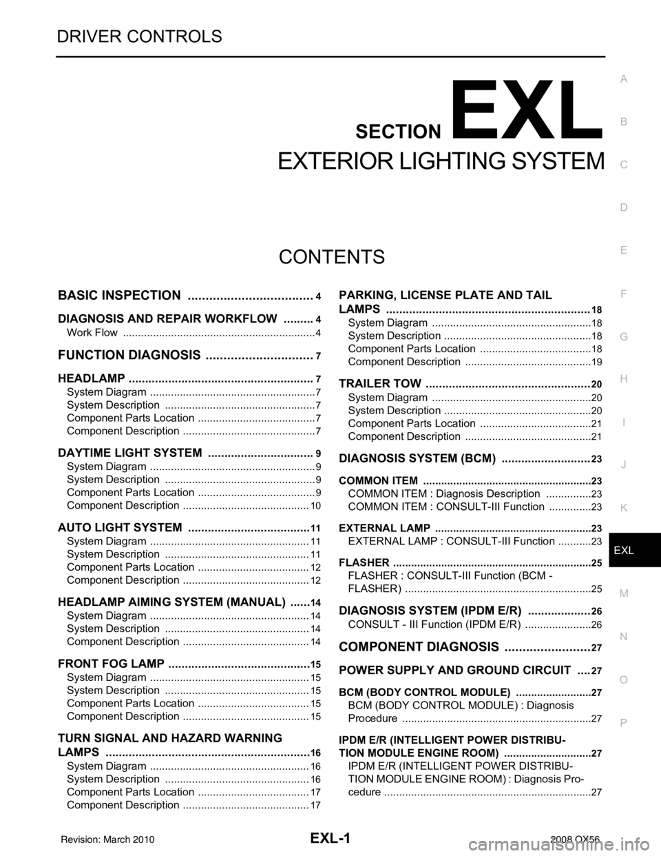
EXTERIOR LIGHTING SYSTEM
BASIC INSPECTION ....... .............................4
DIAGNOSIS AND REPAIR WORKFLOW ..... .....4
Work Flow ........................................................... ......4
FUNCTION DIAGNOSIS ...............................7
HEADLAMP .................................................... .....7
System Diagram .................................................. ......7
System Description ...................................................7
Component Parts Location ........................................7
Component Description .............................................7
DAYTIME LIGHT SYSTEM .................................9
System Diagram .................................................. ......9
System Description ...................................................9
Component Parts Location ........................................9
Component Description ...........................................10
AUTO LIGHT SYSTEM ......................................11
System Diagram ......................................................11
System Description .................................................11
Component Parts Location ......................................12
Component Description ...........................................12
HEADLAMP AIMING SYSTEM (MANUAL) .......14
System Diagram .................................................. ....14
System Description .................................................14
Component Description ...........................................14
FRONT FOG LAMP ............................................15
System Diagram .................................................. ....15
System Description .................................................15
Component Parts Location ......................................15
Component Description ...........................................15
TURN SIGNAL AND HAZARD WARNING
LAMPS ...............................................................
16
System Diagram .................................................. ....16
System Description .................................................16
Component Parts Location ......................................17
Component Description ...........................................17
PARKING, LICENSE PLATE AND TAIL
LAMPS ..............................................................
18
System Diagram .................................................. ....18
System Description ..................................................18
Component Parts Location ......................................18
Component Description ...........................................19
TRAILER TOW ..................................................20
System Diagram ......................................................20
System Description ..................................................20
Component Parts Location ......................................21
Component Description ...........................................21
DIAGNOSIS SYSTEM (BCM) ...........................23
COMMON ITEM ..................................................... ....23
COMMON ITEM : Diagnosis Description ................23
COMMON ITEM : CONSULT-III Function ...............23
EXTERNAL LAMP ................................................. ....23
EXTERNAL LAMP : CONSULT-III Function ............23
FLASHER ............................................................... ....25
FLASHER : CONSULT-III Function (BCM -
FLASHER) ...............................................................
25
DIAGNOSIS SYSTEM (IPDM E/R) ...................26
CONSULT - III Function (IPDM E/R) .......................26
COMPONENT DIAGNOSIS .........................27
POWER SUPPLY AND GROUND CIRCUIT ....27
BCM (BODY CONTROL MODULE) ...................... ....27
BCM (BODY CONTROL MODULE) : Diagnosis
Procedure ............................................................ ....
27
IPDM E/R (INTELLIGENT POWER DISTRIBU-
TION MODULE ENGINE ROOM) .......................... ....
27
IPDM E/R (INTELLIGENT POWER DISTRIBU-
TION MODULE ENGINE ROOM) : Diagnosis Pro-
cedure .................................................................. ....
27
Revision: March 2010 2008 QX56
Page 1930 of 4083

EXL-2
HEADLAMP (HI) CIRCUIT ................................28
Description ........................................................... ...28
Component Function Check ...................................28
Diagnosis Procedure ..............................................28
HEADLAMP (LO) CIRCUIT ...............................30
Description ........................................................... ...30
Component Function Check ...................................30
Diagnosis Procedure ..............................................30
FRONT FOG LAMP CIRCUIT ...........................32
Description ........................................................... ...32
Component Function Check ...................................32
Diagnosis Procedure ..............................................32
PARKING LAMP CIRCUIT ................................34
Description ........................................................... ...34
Component Function Check ...................................34
Diagnosis Procedure ..............................................34
TURN SIGNAL LAMP CIRCUIT ........................37
Description ........................................................... ...37
Component Function Check ...................................37
Diagnosis Procedure ..............................................37
OPTICAL SENSOR ...........................................40
Description ..............................................................40
Component Function Check ...................................40
Diagnosis Procedure ..............................................40
HEADLAMP AIMING SWITCH ..........................42
Description ........................................................... ...42
Diagnosis Procedure ..............................................42
HEADLAMP .......................................................43
Wiring Diagram .................................................... ...43
DAYTIME LIGHT SYSTEM ................................47
Wiring Diagram .................................................... ...47
AUTO LIGHT SYSTEM ......................................54
Wiring Diagram .................................................... ...54
HEADLAMP AIMING SYSTEM (MANUAL) ......61
Wiring Diagram .................................................... ...61
FRONT FOG LAMP SYSTEM ...........................65
Wiring Diagram .................................................... ...65
TURN SIGNAL AND HAZARD WARNING
LAMP SYSTEM .............................................. ...
68
Wiring Diagram .................................................... ...68
PARKING, LICENSE PLATE AND TAIL
LAMPS SYSTEM ............................................ ...
75
Wiring Diagram .................................................... ...75
STOP LAMP ......................................................81
Wiring Diagram .................................................... ...81
BACK-UP LAMP ................................................85
Wiring Diagram .................................................... ...85
TRAILER TOW ..................................................90
Wiring Diagram .................................................... ...90
ECU DIAGNOSIS .......................................99
BCM (BODY CONTROL MODULE) ............... ...99
Description ........................................................... ...99
IPDM E/R (INTELLIGENT POWER DISTRI-
BUTION MODULE ENGINE ROOM) ................
100
Description ........................................................... .100
SYMPTOM DIAGNOSIS ...........................101
EXTERIOR LIGHTING SYSTEM SYMPTOMS ..101
Symptom Table .................................................... .101
NORMAL OPERATING CONDITION ...............103
Description ........................................................... .103
BOTH SIDE HEADLAMPS DO NOT SWITCH
TO HIGH BEAM ................................................
104
Description ........................................................... .104
Diagnosis Procedure .............................................104
BOTH SIDE HEADLAMPS (LO) ARE NOT
TURNED ON .....................................................
105
Description ............................................................105
Diagnosis Procedure .............................................105
PARKING, LICENSE PLATE AND TAIL
LAMPS ARE NOT TURNED ON ......................
106
Description ........................................................... .106
Diagnosis Procedure .............................................106
BOTH SIDE FRONT FOG LAMPS ARE NOT
TURNED ON .....................................................
107
Description ............................................................107
Diagnosis Procedure .............................................107
PRECAUTION ...........................................108
PRECAUTIONS .............................................. ..108
Precaution for Supplemental Restraint System
(SRS) "AIR BAG" and "SEAT BELT PRE-TEN-
SIONER" .............................................................. .
108
Precaution Necessary for Steering Wheel Rota-
tion After Battery Disconnect ................................
108
ON-VEHICLE REPAIR ..............................110
ADJUSTMENT AND INSPECTION ................ ..110
HEADLAMP ............................................................ .110
HEADLAMP : Aiming Adjustment .........................110
FRONT FOG LAMP ................................................ .111
FRONT FOG LAMP : Aiming Adjustment .............111
REMOVAL AND INSTALLATION .............113
HEADLAMP .................................................... ..113
Revision: March 2010 2008 QX56
Page 1948 of 4083

EXL-20
< FUNCTION DIAGNOSIS >
TRAILER TOW
TRAILER TOW
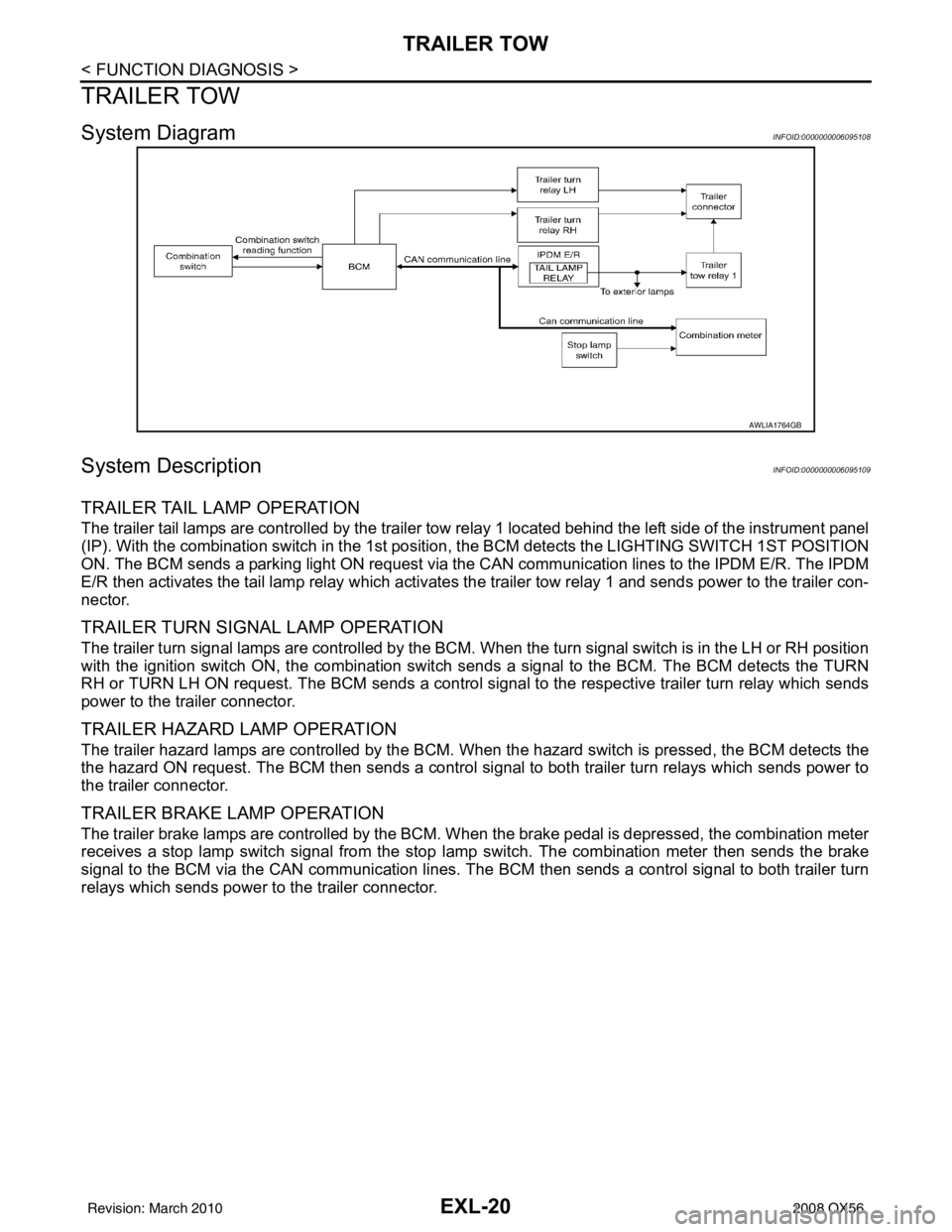
System DiagramINFOID:0000000006095108
System DescriptionINFOID:0000000006095109
TRAILER TAIL LAMP OPERATION
The trailer tail lamps are controlled by the trailer tow relay 1 located behind the left side of the instrument panel
(IP). With the combination switch in the 1st position, the BCM detects the LIGHTING SWITCH 1ST POSITION
ON. The BCM sends a parking light ON request via the CAN communication lines to the IPDM E/R. The IPDM
E/R then activates the tail lamp relay which activates the trailer tow relay 1 and sends power to the trailer con-
nector.
TRAILER TURN SIGNAL LAMP OPERATION
The trailer turn signal lamps are controlled by the BCM. When the turn signal switch is in the LH or RH position
with the ignition switch ON, the combination switch sends a signal to the BCM. The BCM detects the TURN
RH or TURN LH ON request. The BCM sends a control signal to the respective trailer turn relay which sends
power to the trailer connector.
TRAILER HAZARD LAMP OPERATION
The trailer hazard lamps are controlled by the BCM. W hen the hazard switch is pressed, the BCM detects the
the hazard ON request. The BCM then sends a control si gnal to both trailer turn relays which sends power to
the trailer connector.
TRAILER BRAKE LAMP OPERATION
The trailer brake lamps are controlled by the BCM. When the brake pedal is depressed, the combination meter
receives a stop lamp switch signal from the stop lamp switch. The combination meter then sends the brake
signal to the BCM via the CAN communication lines. The BCM then sends a control signal to both trailer turn
relays which sends power to the trailer connector.
AWLIA1764GB
Revision: March 2010 2008 QX56
Page 1949 of 4083

TRAILER TOWEXL-21
< FUNCTION DIAGNOSIS >
C
DE
F
G H
I
J
K
M A
B
EXL
N
O P
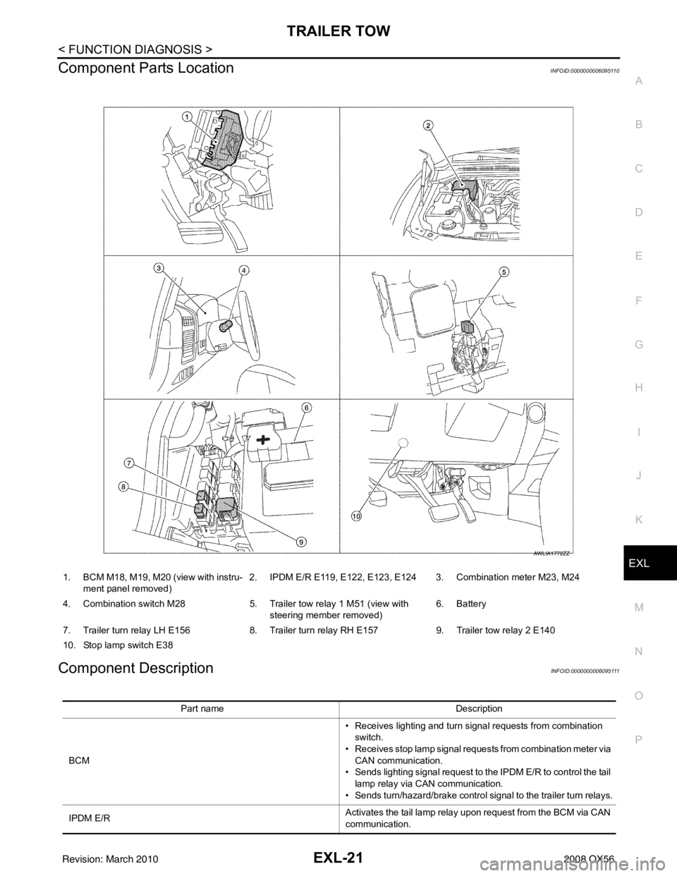
Component Parts LocationINFOID:0000000006095110
Component DescriptionINFOID:0000000006095111
1. BCM M18, M19, M20 (view with instru- ment panel removed) 2. IPDM E/R E119, E122, E123, E124 3. Combination meter M23, M24
4. Combination switch M28 5. Trailer tow relay 1 M51 (view with
steering member removed) 6. Battery
7. Trailer turn relay LH E156 8. Trailer turn relay RH E157 9. Trailer tow relay 2 E140
10. Stop lamp switch E38
AWLIA1772ZZ
Part name Description
BCM • Receives lighting and turn signal requests from combination
switch.
• Receives stop lamp signal requests from combination meter via CAN communication.
• Sends lighting signal request to the IPDM E/R to control the tail
lamp relay via CAN communication.
• Sends turn/hazard/brake control signal to the trailer turn relays.
IPDM E/R Activates the tail lamp relay upon request from the BCM via CAN
communication.
Revision: March 2010
2008 QX56