2008 INFINITI FX35 front suspension
[x] Cancel search: front suspensionPage 3505 of 3924
REAR WHEEL HUB AND KNUCKLERAX-7
< SERVICE INFORMATION >
CEF
G H
I
J
K L
M A
B
RAX
N
O P
9. Remove parking brake cable and parking brake shoe from back plate. Refer to PB-6 and PB-4.
10. Remove fixing nuts of anchor block with power tool , then remove anchor block and back plate from axle.
11. Loosen fixing bolts and nuts of front lower link, radius rod, and rear lower link in side of suspension mem-
ber.
12. Set jack under rear lower link. Then remove fixing bolt in front lower link side of shock absorber with power tool.
13. Remove bolt and nut in axle side of rear lower link with power tool. Then remove coil spring. Refer to RSU-15
.
14. Remove fixing bolts and nuts in axle side of fr ont lower link, radius rod with power tool.
15. Remove suspension arm and cotter pin at axle, then loosen mounting nut.
16. Use a ball joint remover (suitable tool) to remove suspension arm from axle. Be careful not to damage ball joint boot.
CAUTION:
Tighten temporarily mounting nu t to prevent damage to threads and to prevent ball joint remover
(suitable tool) from coming off.
17. Remove axle from vehicle.
INSPECTION AFTER REMOVAL
Check for deformity, cracks and damage on each parts, replace if necessary.
Ball Joint Inspection
Check for boot breakage, axial looseness, and tor que of suspension arm ball joint. Refer to RSU-11, "Removal
and Installation".
INSTALLATION
Refer to "Removal and Installation" for tightening torque. Install in the reverse order of removal.
NOTE:
Refer to component parts location and do not reuse non-reusable parts.
Perform final tightening of installation position of suspension links (rubber bushing) under unladen conditions
with tires on level ground, Check wheel alignment. Refer to RSU-5, "
Wheel AlignmentInspection".
After adjusting wheel alignment, adjust neutral position of steering angle sensor. Refer to BRC-8, "
Adjust-
ment of Steering Angle Sensor Neutral Position".
Disassembly and AssemblyINFOID:0000000001327528
DISASSEMBLY
Wheel Bearing
CAUTION:
Do not disassemble if wheel bearing has no trouble.
1. Remove wheel bearing fixing bolts and anchor block fixing nuts, and remove wheel hub and bearing assembly, back plate and anchor block from axle.
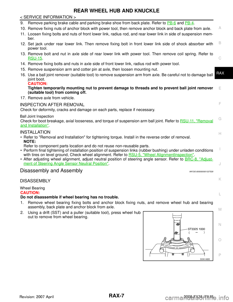
2. Using a drift (SST) and a puller (suitable tool), press wheel hub out to remove from wheel bearing.
SDIA1482E
3AA93ABC3ACD3AC03ACA3AC03AC63AC53A913A773A893A873A873A8E3A773A983AC73AC93AC03AC3
3A893A873A873A8F3A773A9D3AAF3A8A3A8C3A863A9D3AAF3A8B3A8C
Page 3582 of 3924
RSU-1
SUSPENSION
C
DF
G H
I
J
K L
M
SECTION RSU
A
B
RSU
N
O PCONTENTS
REAR SUSPENSION
SERVICE INFORMATION .. ..........................2
PRECAUTIONS .............................................. .....2
Cautions .............................................................. ......2
PREPARATION ...................................................3
Special Service Tool ........................................... ......3
Commercial Service Tool ..........................................3
NOISE, VIBRATION AND HARSHNESS
(NVH) TROUBLESHOOTING .............................
4
NVH Troubleshooting Chart ................................ ......4
REAR SUSPENSION ASSEMBLY .....................5
On-Vehicle Inspection and Service ..................... ......5
Wheel AlignmentInspection .......................................5
Removal and Installation ...........................................6
SHOCK ABSORBER ..........................................9
Removal and Installation ..................................... ......9
Disassembly and Assembly ......................................9
SUSPENSION ARM ..........................................11
Removal and Installation ..................................... ....11
RADIUS ROD ................................... .................13
Removal and Installation ..................................... ....13
FRONT LOWER LINK .......................................14
Removal and Installation .........................................14
REAR LOWER LINK & COIL SPRING .............15
Removal and Installation .........................................15
STABILIZER BAR .............................................16
Removal and Installation .........................................16
REAR SUSPENSION MEMBER .......................17
Removal and Installation ..................................... ....17
SERVICE DATA AND SPECIFICATIONS
(SDS) .................................................................
18
Wheel Alignment (Unladen*) ...................................18
Ball Joint ..................................................................18
Wheelarch Height (Unladen*) ..................................18
3AA93ABC3ACD3AC03ACA3AC03AC63AC53A913A773A893A873A873A8E3A773A983AC73AC93AC03AC3
3A893A873A873A8F3A773A9D3AAF3A8A3A8C3A863A9D3AAF3A8B3A8C
Page 3587 of 3924
RSU-6
< SERVICE INFORMATION >
REAR SUSPENSION ASSEMBLY
- Use the “Jacking Compensation Method”. After installing the alignment targets or head units, raise the vehi-
cle and rotate the wheels 1/2 turn both ways.
- See Instructions in the alignment machine you're using for more information on this.
CAMBER INSPECTION
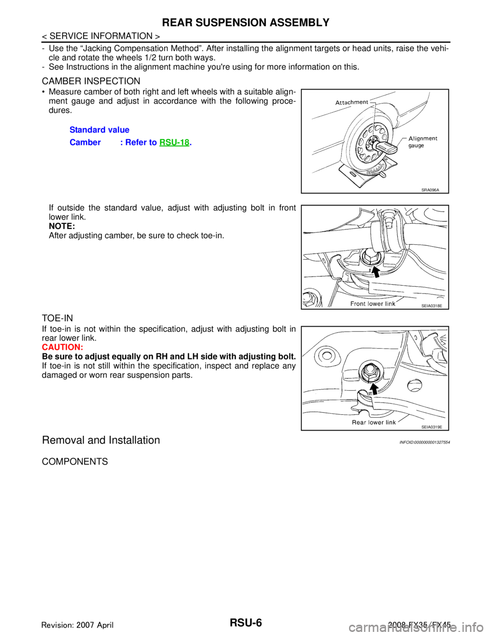
Measure camber of both right and left wheels with a suitable align-
ment gauge and adjust in accordance with the following proce-
dures.
If outside the standard value, adjust with adjusting bolt in front
lower link.
NOTE:
After adjusting camber, be sure to check toe-in.
TOE-IN
If toe-in is not within the specif ication, adjust with adjusting bolt in
rear lower link.
CAUTION:
Be sure to adjust equally on RH and LH side with adjusting bolt.
If toe-in is not still within the specification, inspect and replace any
damaged or worn rear suspension parts.
Removal and InstallationINFOID:0000000001327554
COMPONENTS
Standard value
Camber : Refer to RSU-18
.
SRA096A
SEIA0318E
SEIA0319E
3AA93ABC3ACD3AC03ACA3AC03AC63AC53A913A773A893A873A873A8E3A773A983AC73AC93AC03AC3
3A893A873A873A8F3A773A9D3AAF3A8A3A8C3A863A9D3AAF3A8B3A8C
Page 3588 of 3924
REAR SUSPENSION ASSEMBLYRSU-7
< SERVICE INFORMATION >
C
DF
G H
I
J
K L
M A
B
RSU
N
O P
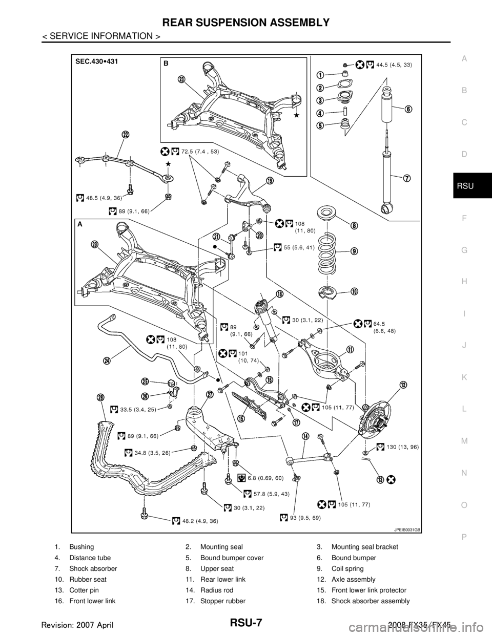
1. Bushing 2. Mounting seal 3. Mounting seal bracket
4. Distance tube 5. Bound bumper cover 6. Bound bumper
7. Shock absorber 8. Upper seat 9. Coil spring
10. Rubber seat 11. Rear lower link 12. Axle assembly
13. Cotter pin 14. Radius rod 15. Front lower link protector
16. Front lower link 17. Stopper rubber 18. Shock absorber assembly
JPEIB0031GB
3AA93ABC3ACD3AC03ACA3AC03AC63AC53A913A773A893A873A873A8E3A773A983AC73AC93AC03AC3
3A893A873A873A8F3A773A9D3AAF3A8A3A8C3A863A9D3AAF3A8B3A8C
Page 3595 of 3924
RSU-14
< SERVICE INFORMATION >
FRONT LOWER LINK
FRONT LOWER LINK
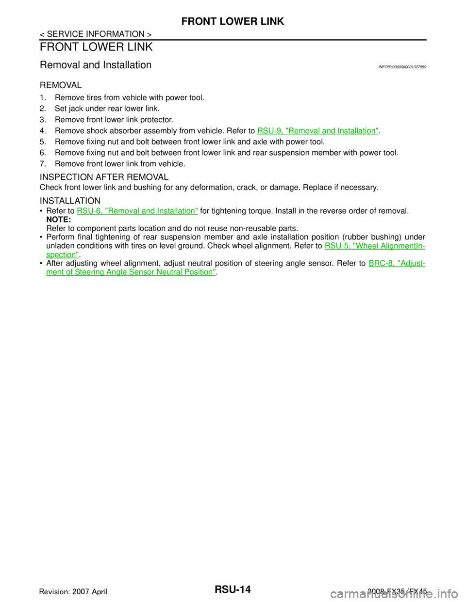
Removal and InstallationINFOID:0000000001327559
REMOVAL
1. Remove tires from vehicle with power tool.
2. Set jack under rear lower link.
3. Remove front lower link protector.
4. Remove shock absorber assembly from vehicle. Refer to RSU-9, "
Removal and Installation".
5. Remove fixing nut and bolt between front lower link and axle with power tool.
6. Remove fixing nut and bolt between front lower li nk and rear suspension member with power tool.
7. Remove front lower link from vehicle.
INSPECTION AFTER REMOVAL
Check front lower link and bushing for any deforma tion, crack, or damage. Replace if necessary.
INSTALLATION
Refer to RSU-6, "Removal and Installation" for tightening torque. Install in the reverse order of removal.
NOTE:
Refer to component parts location and do not reuse non-reusable parts.
Perform final tightening of rear suspension member and axle installation position (rubber bushing) under
unladen conditions with tires on level ground. Check wheel alignment. Refer to RSU-5, "
Wheel AlignmentIn-
spection".
After adjusting wheel alignment, adjust neutral position of steering angle sensor. Refer to BRC-8, "
Adjust-
ment of Steering Angle Sensor Neutral Position".
3AA93ABC3ACD3AC03ACA3AC03AC63AC53A913A773A893A873A873A8E3A773A983AC73AC93AC03AC3
3A893A873A873A8F3A773A9D3AAF3A8A3A8C3A863A9D3AAF3A8B3A8C
Page 3598 of 3924
REAR SUSPENSION MEMBERRSU-17
< SERVICE INFORMATION >
C
DF
G H
I
J
K L
M A
B
RSU
N
O P
REAR SUSPENSION MEMBER
Removal and InstallationINFOID:0000000001327562
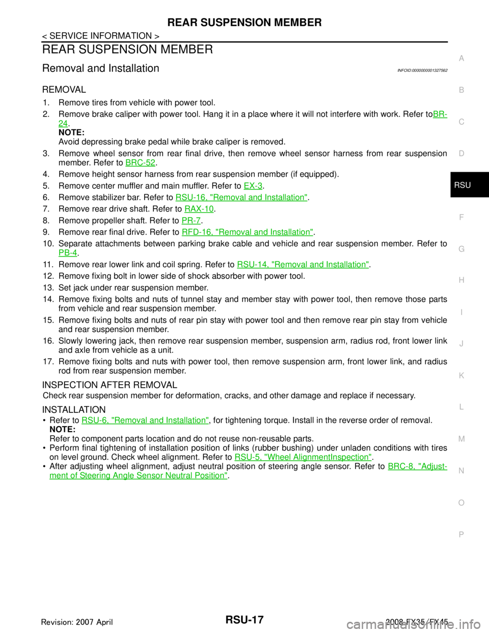
REMOVAL
1. Remove tires from vehicle with power tool.
2. Remove brake caliper with power tool. Hang it in a place where it will not interfere with work. Refer to BR-
24.
NOTE:
Avoid depressing brake pedal while brake caliper is removed.
3. Remove wheel sensor from rear final drive, t hen remove wheel sensor harness from rear suspension
member. Refer to BRC-52
.
4. Remove height sensor harness from rear suspension member (if equipped).
5. Remove center muffler and main muffler. Refer to EX-3
.
6. Remove stabilizer bar. Refer to RSU-16, "
Removal and Installation".
7. Remove rear drive shaft. Refer to RAX-10
.
8. Remove propeller shaft. Refer to PR-7
.
9. Remove rear final drive. Refer to RFD-16, "
Removal and Installation".
10. Separate attachments between parking brake cable and vehicle and rear suspension member. Refer to PB-4
.
11. Remove rear lower link and coil spring. Refer to RSU-14, "
Removal and Installation".
12. Remove fixing bolt in lower side of shock absorber with power tool.
13. Set jack under rear suspension member.
14. Remove fixing bolts and nuts of tunnel stay and member stay with power tool, then remove those parts from vehicle and rear suspension member.
15. Remove fixing bolts and nuts of rear pin stay with pow er tool and then remove rear pin stay from vehicle
and rear suspension member.
16. Slowly lowering jack, then remove rear suspension me mber, suspension arm, radius rod, front lower link
and axle from vehicle as a unit.
17. Remove fixing bolts and nuts with power tool, then re move suspension arm, front lower link, and radius
rod from rear suspension member.
INSPECTION AFTER REMOVAL
Check rear suspension member for deformation, cracks, and other damage and replace if necessary.
INSTALLATION
Refer to RSU-6, "Removal and Installation", for tightening torque. Install in the reverse order of removal.
NOTE:
Refer to component parts location and do not reuse non-reusable parts.
Perform final tightening of installation position of links (rubber bushing) under unladen conditions with tires
on level ground. Check wheel alignment. Refer to RSU-5, "
Wheel AlignmentInspection".
After adjusting wheel alignment, adjust neutral position of steering angle sensor. Refer to BRC-8, "
Adjust-
ment of Steering Angle Sensor Neutral Position".
3AA93ABC3ACD3AC03ACA3AC03AC63AC53A913A773A893A873A873A8E3A773A983AC73AC93AC03AC3
3A893A873A873A8F3A773A9D3AAF3A8A3A8C3A863A9D3AAF3A8B3A8C
Page 3846 of 3924
WT-6
< SERVICE INFORMATION >
NOISE, VIBRATION AND HARSHNESS (NVH) TROUBLESHOOTING
NOISE, VIBRATION AND HARSHNESS (NVH) TROUBLESHOOTING
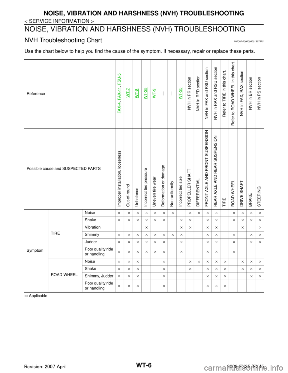
NVH Troubleshooting ChartINFOID:0000000001327572
Use the chart below to help you find the cause of the sy mptom. If necessary, repair or replace these parts.
×: Applicable
Reference
FAX-4
,
FAX-11
, FSU-5
WT-7WT-8WT-35WT-9—
—
WT-35
NVH in PR section
NVH in RFD section
NVH in FAX and FSU section
NVH in RAX and RSU section Refer to TIRE in this chart.
Refer to ROAD WHEEL in this chart. NVH in FAX, RAX sectionNVH in BR section
NVH in PS section
Possible cause an d SUSPECTED PARTS
Improper installation, looseness
Out-of-round
Unbalance
Incorrect tire pressure
Uneven tire wear
Deformation or damage
Non-uniformity
Incorrect tire size
PROPELLER SHAFT
DIFFERENTIAL
FRONT AXLE AND FRONT SUSPENSION
REAR AXLE AND REAR SUSPENSION
TIRE
ROAD WHEEL
DRIVE SHAFT
BRAKE
STEERING
SymptomTIRE Noise
× ×××××× ×××× ××××
Shake ××××××××××××××
Vibration ×××××××
Shimmy × ××××××× ×× × ××
Judder ××××××× ×××××
Poor quality ride
or handling × ××××× × ×× ×
ROAD WHEEL Noise
× ×× × ××××× ×××
Shake × ×× × × ××× ×××
Shimmy, Judder ×××× ×××××
Poor quality ride
or handling ××× × ×××
3AA93ABC3ACD3AC03ACA3AC03AC63AC53A913A773A893A873A873A8E3A773A983AC73AC93AC03AC3
3A893A873A873A8F3A773A9D3AAF3A8A3A8C3A863A9D3AAF3A8B3A8C