2008 INFINITI FX35 front suspension
[x] Cancel search: front suspensionPage 2668 of 3924

EM-184
< SERVICE INFORMATION >[VK45DE]
OIL PAN AND OIL STRAINER
Do not spill engine oil on drive belts.
6. Drain engine coolant. Refer to CO-37, "
Changing Engine Coolant".
CAUTION:
Perform this step when engine is cold.
Do not spill engine coolant on drive belts.
7. Remove drive belts. Refer to EM-170, "
Component".
8. Remove auto tensioner of power steering oil pump belt. Refer to EM-172, "
Drive Belt Auto Tensioner and
Idler Pulley".
9. Remove power steering oil pump with piping connect ed, and temporarily secure it aside with ropes or
equivalent. Refer to PS-27, "
On-Vehicle Inspection and Service".
10. Remove A/C compressor with piping connected, and tem porarily secure it aside with ropes or equivalent.
Refer to ATC-121, "
Component".
11. Remove A/C compressor fitting bolts, and install A/C compressor temporarily on vehicle side with ropes or equivalent.
12. Remove harness of lower side of oil pan.
13. Remove crankshaft position sensor (POS) from transmission. CAUTION:
Handle carefully to avoid dropping and shocks.
Do not disassemble it.
Do not allow metal powder to adhere to magnetic part at sensor tip.
Do not place sensors in a location wh ere they are exposed to magnetism.
14. Install engine slinger and hang engine assembly to secure position. Refer to EM-237, "
Component".
15. Remove front suspension member with power tool. Refer to FSU-16, "
Removal and Installation".
16. Remove front final drive assembly. Refer to FFD-14, "
Removal and Installation (VQ35DE Models)".
17. Remove oil filter. Refer to LU-26, "
Removal and Installation".
18. Disconnect oil cooler water hoses, and remove oil cooler water pipe and oil cooler. Refer to LU-27, "
Com-
ponent".
19. Remove oil pan as the follows:
a. Remove rear plate cover.
b. Remove transmission joint bolts which pierce oil pan. Refer to AT-243, "
Removal and Installation (AWD
Models)".
c. Loosen mounting bolts with power tool in reverse order as shown in the figure.
NOTE:
Disregard the numerical order No. 11 and 17 in removal.
d. Insert seal cutter (SST) between oil pan and cylinder block. Slide seal cutter by tapping on the side of seal cutter with ham-
mer. Remove oil pan.
CAUTION:
Be careful not to damage the mating surfaces.
Do not insert screwdriver, th is will damage the mating
surface.
e. Remove O-rings from bottom of oil pump and front cover.
20. As necessary, pull axle pipe from oil pan.
PBIC0194E
SEM365E
3AA93ABC3ACD3AC03ACA3AC03AC63AC53A913A773A893A873A873A8E3A773A983AC73AC93AC03AC3
3A893A873A873A8F3A773A9D3AAF3A8A3A8C3A863A9D3AAF3A8B3A8C
Page 2721 of 3924

ENGINE ASSEMBLYEM-237
< SERVICE INFORMATION > [VK45DE]
C
D
E
F
G H
I
J
K L
M A
EM
NP
O
ENGINE ASSEMBLY
ComponentINFOID:0000000001325801
Refer to
GI-8, "Component" for symbols in the figure.
Removal and InstallationINFOID:0000000001325802
WARNING:
Situate vehicle on a flat and solid surface.
Place chocks at front and back of rear wheels.
For engines not equipped with engi ne slingers, attach proper slingers and bolts described in PARTS
CATALOG.
CAUTION:
Always be careful to work safely, avoid forceful or uninstructed operations.
Do not start working until exhaust system and engine coolant are cool enough.
If items or work required are not covered by th e engine section, refer to the applicable sections.
Always use the support poin t specified for lifting.
Use either 2-pole lift type or separate type lift as best you can. If board-on type is used for unavoid-
able reasons, support at the rear axle jacking poin t with transmission jack or similar tool before
starting work, in prepar ation for the backward shif t of center of gravity.
For supporting points fo r lifting and jacking point at rear axle, refer to GI-37, "
Garage Jack and
Safety Stand".
REMOVAL
Outline
At first, remove engine, transmission assembly and front final drive with front suspension member from vehicle
downward. Then separate engine from transmission.
Preparation
1. Engine mounting bracket (RH) 2. Engine mounting insulator (RH) 3. Engine mounting bracket (LH)
4. Engine mounting insulator (LH) 5. Plate 6. Collar
7. Grommet 8. Engine rear member 9. Engine mounting insulator (rear)
JPBIA0902GB
3AA93ABC3ACD3AC03ACA3AC03AC63AC53A913A773A893A873A873A8E3A773A983AC73AC93AC03AC3
3A893A873A873A8F3A773A9D3AAF3A8A3A8C3A863A9D3AAF3A8B3A8C
Page 2723 of 3924

ENGINE ASSEMBLYEM-239
< SERVICE INFORMATION > [VK45DE]
C
D
E
F
G H
I
J
K L
M A
EM
NP
O
10. Disconnect steering lower joint at power steering gear
assembly side, and release steering lower shaft.
Refer to PS-12, "
Removal and Installation".
11. Remove rear propeller shaft. Refer to PR-7, "
On-Vehicle Inspection".
After disconnection, plug the opening on transmission side.
12. Remove front drive shaft (both side). Refer to FAX-13, "
On-Vehicle Inspection".
13. Remove front propeller shaft. Refer to PR-4, "
On-Vehicle Inspection".
14. Remove three way catalyst (both bank). Refer to EM-179, "
Component".
Removal Work
1. Install engine slingers into front of cylinder head (left bank) and
front of cylinder head (right bank).
2. Lift with hoist and secure engine in position.
3. Use manual lift table caddy (commercial service tool) or equivalently rigid tool such as transmission jack. Securely support bottom of suspension member and transmission.
CAUTION:
Put a piece of wood or something similar as the supporting surface, secure a completely stable
condition.
4. Remove engine rear member mounting bolts.
5. Remove front suspension member mounting nuts with power tool. Refer to FSU-5, "
On-Vehicle Inspection
and Service".
6. Carefully lower jack, or raise lift to remove engine, transmission front final drive and front suspension member assembly. When
performing work, observe the following caution:
CAUTION:
Confirm there is no interference with vehicle.
Make sure that all connectio n points have been discon-
nected.
Keep in mind the center of veh icle gravity changes. If nec-
essary, use jack(s) to support vehicle at rear jacking
point(s) to prevent it from falling it off the lift.
Separation Work
1. Change engine slinger installing to cylinder head (right bank).
NOTE:
In order to keep secure position when hoisting engine.
2. Remove engine mounting insulators (RH and LH) under side nut with power tool.
3. Lift with hoist and separate engine and transmission assembly from front suspension member. CAUTION:
Before and during this lifting, always make sure that any harnesses are left connected.
Slinger bolts:
: 33.4 N·m (3.4 kg-m, 25 ft-lb)
PBIC1556E
PBIC1557E
Slinger bolts: : 33.4 N·m (3.4 kg-m, 25 ft-lb)
PBIC2447E
3AA93ABC3ACD3AC03ACA3AC03AC63AC53A913A773A893A873A873A8E3A773A983AC73AC93AC03AC3
3A893A873A873A8F3A773A9D3AAF3A8A3A8C3A863A9D3AAF3A8B3A8C
Page 2726 of 3924

EM-242
< SERVICE INFORMATION >[VK45DE]
CYLINDER BLOCK
Refer to
GI-8, "Component" for symbols in the figure.
Disassembly and AssemblyINFOID:0000000001325804
DISASSEMBLY
NOTE:
Explained here is how to disassemble with engine stand supporting transmission surface. When using differ-
ent type of engine stand, note with difference in steps and etc.
1. Remove engine assembly from vehicle, and separa te front suspension member, transmission and front
final drive from engine. Refer to EM-237, "
Component".
2. Remove the parts that may restrict installation of engine to widely use engine stand. NOTE:
The procedure is described assuming that you use wi dely use engine holding the surface, to which trans-
mission is installed.
a. Remove drive plate. Holding ring gear with ring gear stopper (SST).
Loosen mounting bolts diagonally order.
CAUTION:
Do not disassemble drive plate.
Do not place drive plate with signal plate facing down.
When handling signal plate, take care not to damage or scratch it.
Handle signal plate in a manner that prevents it from becoming magnetized.
b. Remove engine rear plate.
3. Lift engine with hoist to install it onto widely use engine stand. CAUTION:
Use engine stand that has a load capacity [approximately 240 kg ( 529 lb) or more] large enough for
supporting the engine weight.
If the load capacity of stand is not adequate, remo ve the following parts beforehand to reduce the poten-
tial risk of overturning stand.
- Intake manifolds (upper and lower): Refer to EM-175, "
Component".
- Exhaust manifold: Refer to EM-179, "
Component".
- Fuel tube and fuel injector assembly: Refer to EM-190, "
Component".
22. Main bearing 23. Rear plate 24. Crankshaft
25. Pilot converter 26. Drive plate 27. Thrust bearing
28. Side bolt 29. Reinforcement plate 30. Crankshaft position sensor (POS)
31. O-ring 32. Rear oil seal 33. Rear oil seal retainer
A.Refererence: Installed on transmis-
sion B. Refer to
EM-242
C. Right bank
D. Cylinder block heater (For Canada) E. Chamfered F. Crankshaft side : Engine front
PBIC1656E
PBIC2367E
3AA93ABC3ACD3AC03ACA3AC03AC63AC53A913A773A893A873A873A8E3A773A983AC73AC93AC03AC3
3A893A873A873A8F3A773A9D3AAF3A8A3A8C3A863A9D3AAF3A8B3A8C
Page 2775 of 3924

FAX-10
< SERVICE INFORMATION >[AWD]
NOISE, VIBRATION AND HARSHNESS
(NVH) TROUBLESHOOTING
NOISE, VIBRATION AND HARSHNESS (NVH) TROUBLESHOOTING
NVH Troubleshooting ChartINFOID:0000000001327512
Use chart below to help you find the cause of the symp tom. If necessary, repair or replace these parts.
×: ApplicableReference page
—
FA X - 1 8—
FAX-11—
FAX-11
NVH in FFD section
NVH in FAX and FSU section
Refer to FRONT AXLE in this chart. NVH in WT section
NVH in WT section
Refer to DRIVE SHAFT in this chart. NVH in BR sectionNVH in PS section
Possible cause and SUSPECTED PARTS
Excessive joint angle
Joint sliding resistance
Imbalance
Improper installation, looseness
Parts interference
Wheel bearing damage
FRONT DIFFERENTIAL
FRONT AXLE AND FRONT SUSPENSION
FRONT AXLE
TIRE
ROAD WHEEL
DRIVE SHAFT
BRAKE
STEERING
Symptom DRIVE
SHAFT
Noise
×× ×××××× ××
Shake ×× ×××××××
FRONT
AXLE Noise
×××× ××××××
Shake ××× ××××××
Vibration ××× ××××
Shimmy ×× ××× ××
Judder × ××× ××
Poor quality ride or handling ×× ×××
3AA93ABC3ACD3AC03ACA3AC03AC63AC53A913A773A893A873A873A8E3A773A983AC73AC93AC03AC3
3A893A873A873A8F3A773A9D3AAF3A8A3A8C3A863A9D3AAF3A8B3A8C
Page 2805 of 3924
FFD-14
< SERVICE INFORMATION >
FRONT FINAL DRIVE ASSEMBLY
FRONT FINAL DRIVE ASSEMBLY
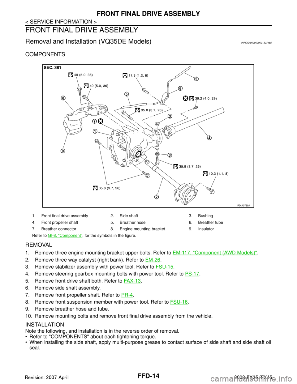
Removal and Installation (VQ35DE Models)INFOID:0000000001327485
COMPONENTS
REMOVAL
1. Remove three engine mounting bracket upper bolts. Refer to EM-117, "Component (AWD Models)".
2. Remove three way catalyst (right bank). Refer to EM-26
.
3. Remove stabilizer assembly with power tool. Refer to FSU-15
.
4. Remove steering gearbox mounting bolts with power tool. Refer to PS-17
.
5. Remove front drive shaft both. Refer to FA X - 1 3
.
6. Remove side shaft assembly.
7. Remove front propeller shaft. Refer to PR-4
.
8. Remove front suspension member with power tool. Refer to FSU-16
.
9. Remove breather hose and tube.
10. Remove mounting bolts and remove front final drive assembly from the vehicle.
INSTALLATION
Note the following, and installation is in the reverse order of removal.
Refer to "COMPONENTS" about each tightening torque.
When installing the side shaft, apply multi-purpose grease to contact surface of side shaft and side shaft oil
seal.
1. Front final drive assembly 2. Side shaft 3. Bushing
4. Front propeller shaft 5. Breather hose 6. Breather tube
7. Breather connector 8. Engine mounting bracket 9. Insulator
Refer to GI-8, "
Component", for the symbols in the figure.
PDIA0789J
3AA93ABC3ACD3AC03ACA3AC03AC63AC53A913A773A893A873A873A8E3A773A983AC73AC93AC03AC3
3A893A873A873A8F3A773A9D3AAF3A8A3A8C3A863A9D3AAF3A8B3A8C
Page 2807 of 3924
FFD-16
< SERVICE INFORMATION >
FRONT FINAL DRIVE ASSEMBLY
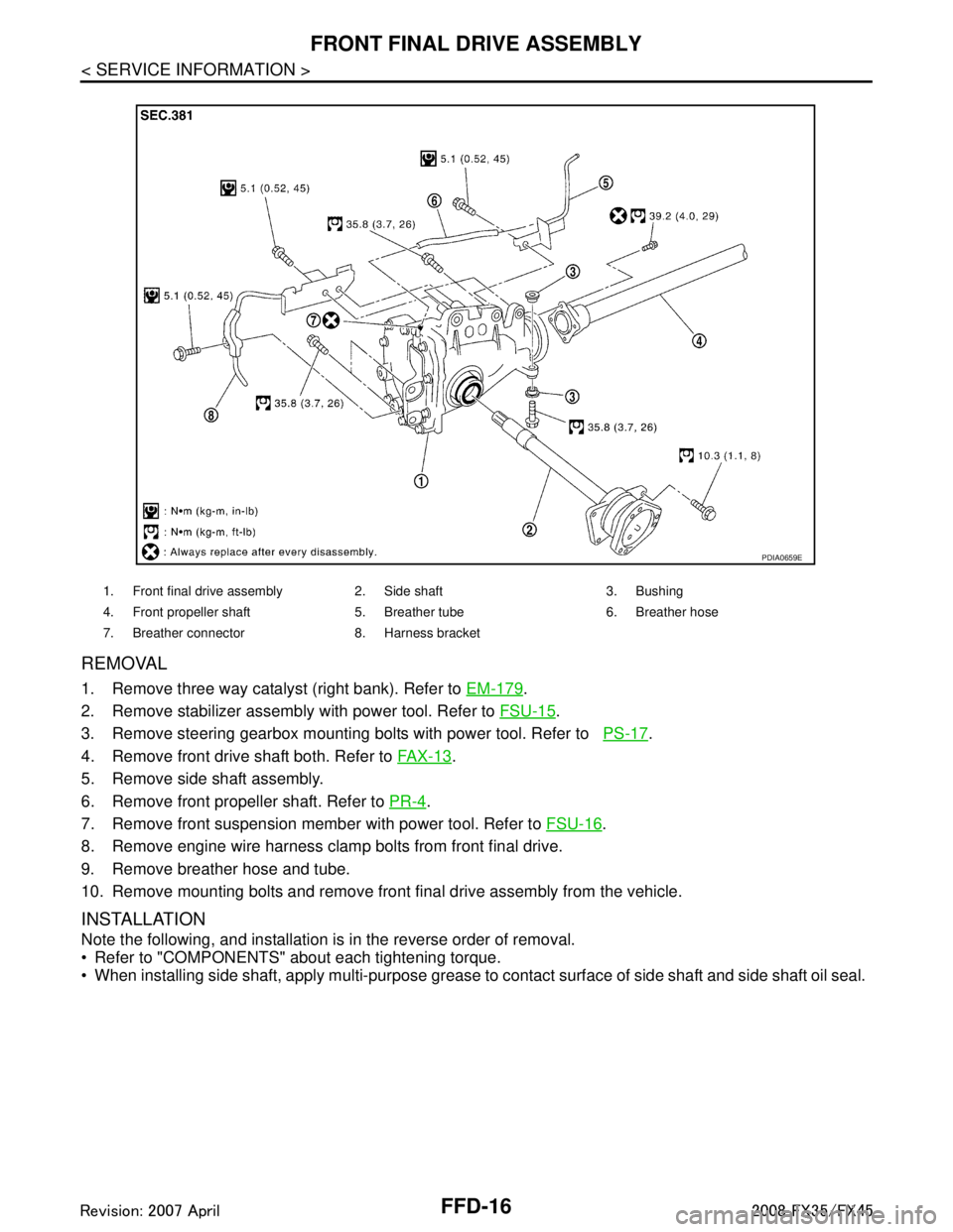
REMOVAL
1. Remove three way catalyst (right bank). Refer to EM-179.
2. Remove stabilizer assembly with power tool. Refer to FSU-15
.
3. Remove steering gearbox mounting bolts with power tool. Refer to PS-17
.
4. Remove front drive shaft both. Refer to FA X - 1 3
.
5. Remove side shaft assembly.
6. Remove front propeller shaft. Refer to PR-4
.
7. Remove front suspension member with power tool. Refer to FSU-16
.
8. Remove engine wire harness clamp bolts from front final drive.
9. Remove breather hose and tube.
10. Remove mounting bolts and remove front final drive assembly from the vehicle.
INSTALLATION
Note the following, and installation is in the reverse order of removal.
Refer to "COMPONENTS" about each tightening torque.
When installing side shaft, apply multi-purpose grease to contact surface of side shaft and side shaft oil seal.
1. Front final drive assembly 2. Side shaft 3. Bushing
4. Front propeller shaft 5. Breather tube 6. Breather hose
7. Breather connector 8. Harness bracket
PDIA0659E
3AA93ABC3ACD3AC03ACA3AC03AC63AC53A913A773A893A873A873A8E3A773A983AC73AC93AC03AC3
3A893A873A873A8F3A773A9D3AAF3A8A3A8C3A863A9D3AAF3A8B3A8C
Page 2842 of 3924
FL-10
< SERVICE INFORMATION >
FUEL TANK
FUEL TANK
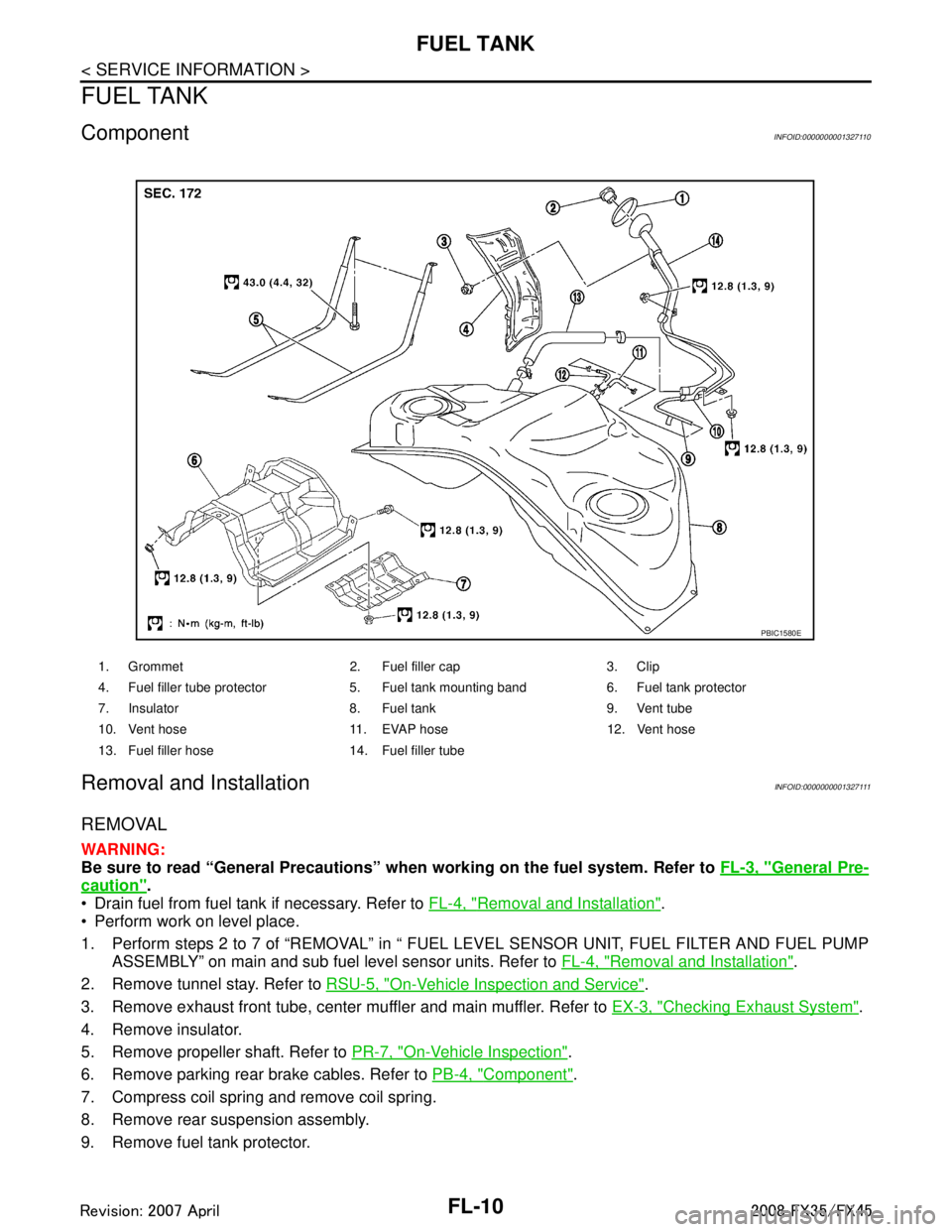
ComponentINFOID:0000000001327110
Removal and InstallationINFOID:0000000001327111
REMOVAL
WARNING:
Be sure to read “General Precautions” when working on the fuel system. Refer to FL-3, "
General Pre-
caution".
Drain fuel from fuel tank if necessary. Refer to FL-4, "
Removal and Installation".
Perform work on level place.
1. Perform steps 2 to 7 of “REMOVAL” in “ FUEL LEVEL SENSOR UNIT, FUEL FILTER AND FUEL PUMP
ASSEMBLY” on main and sub fuel level sensor units. Refer to FL-4, "
Removal and Installation".
2. Remove tunnel stay. Refer to RSU-5, "
On-Vehicle Inspection and Service".
3. Remove exhaust front tube, center muffler and main muffler. Refer to EX-3, "
Checking Exhaust System".
4. Remove insulator.
5. Remove propeller shaft. Refer to PR-7, "
On-Vehicle Inspection".
6. Remove parking rear brake cables. Refer to PB-4, "
Component".
7. Compress coil spring and remove coil spring.
8. Remove rear suspension assembly.
9. Remove fuel tank protector.
1. Grommet 2. Fuel filler cap 3. Clip
4. Fuel filler tube protector 5. Fuel tank mounting band 6. Fuel tank protector
7. Insulator 8. Fuel tank 9. Vent tube
10. Vent hose 11. EVAP hose 12. Vent hose
13. Fuel filler hose 14. Fuel filler tube
PBIC1580E
3AA93ABC3ACD3AC03ACA3AC03AC63AC53A913A773A893A873A873A8E3A773A983AC73AC93AC03AC3
3A893A873A873A8F3A773A9D3AAF3A8A3A8C3A863A9D3AAF3A8B3A8C