2008 INFINITI FX35 Brake
[x] Cancel search: BrakePage 2848 of 3924
FSU-4
< SERVICE INFORMATION >
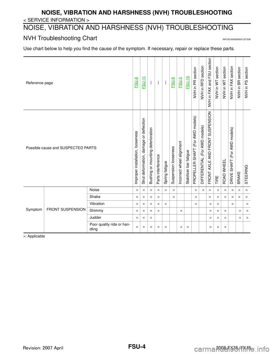
NOISE, VIBRATION AND HARSHNESS (NVH) TROUBLESHOOTING
NOISE, VIBRATION AND HARSHNESS (NVH) TROUBLESHOOTING
NVH Troubleshooting ChartINFOID:0000000001327536
Use chart below to help you find the cause of the symp tom. If necessary, repair or replace these parts.
×: ApplicableReference page
FSU-6FSU-11
—
—
—
FSU-6FSU-5FSU-15
NVH in PR section
NVH in RFD section
NVH in FAX and FSU section
NVH in WT section
NVH in WT section
NVH in FAX section NVH in BR sectionNVH in PS section
Possible cause and SUSPECTED PARTS
Improper installation, looseness
Strut deformation, damage or deflection
Bushing or mounting deterioration
Parts interference
Spring fatigue
Suspension looseness
Incorrect wheel alignment
Stabilizer bar fatigue
PROPELLER SHAFT (For AWD models)
DIFFERENTIAL (For AWD models)
FRONT AXLE AND FRONT SUSPENSION
TIRE
ROAD WHEEL
DRIVE SHAFT (For AWD models)
BRAKE
STEERING
Symptom FRONT SUSPENSION Noise
××××× × ××× ×××××
Shake ×××× × × × ×××××
Vibration ××××× × ×× × ×
Shimmy ×××× × ××× ××
Judder ××× ××× ××
Poor quality ride or han-
dling ×× × × × ×× × × ×
3AA93ABC3ACD3AC03ACA3AC03AC63AC53A913A773A893A873A873A8E3A773A983AC73AC93AC03AC3
3A893A873A873A8F3A773A9D3AAF3A8A3A8C3A863A9D3AAF3A8B3A8C
Page 2849 of 3924

FRONT SUSPENSION ASSEMBLYFSU-5
< SERVICE INFORMATION >
C
DF
G H
I
J
K L
M A
B
FSU
N
O P
FRONT SUSPENSION ASSEMBLY
On-Vehicle Inspection and ServiceINFOID:0000000001327537
Make sure the mounting conditions (looseness, back lash) of each component and component conditions
(wear, damage) are normal.
INSPECTION LOWER BALL JOINT END PLAY
1. Set front wheels in a straight-ahead position. Do not depress brake pedal.
2. Place an iron bar or similar tool bet ween transverse link and steering knuckle.
3. Measure axial end play by prying it up and down.
CAUTION:
Be careful not to damage ball joint boot.
STRUT INSPECTION
Check strut for oil leakage, damage and replace if there are. Refer to FSU-10.
Wheel Alignment InspectionINFOID:0000000001327538
DESCRIPTION
Measure wheel alignment under unladen conditions.
NOTE:
Unladen conditions mean that fuel, engine coolant, and l ubricant are full. Spare tire, jack, hand tools and
mats are designated positions.
PRELIMINARY CHECK
Check tires for improper air pressure and wear.
Check road wheels for runout.
Check wheel bearing axial end play.
Check ball joint axial end play of compression rod, upper link, and steering knuckle
Check shock absorber operation.
Check each mounting part of axle and suspension for looseness and deformation.
Check each link, rod and member for cracks, deformation and other damage.
Check vehicle posture.
GENERAL INFORMATION AND RECOMMENDATIONS
A four-wheel thrust alignment should be performed.
- This type of alignment is recomm ended for any NISSAN/INFINITI vehicle.
- The four-wheel “thrust” process helps ensure that t he vehicle is properly aligned and the steering wheel is
centered.
- The alignment rack itself should be capable of accepting any NISSAN/INFINITI vehicle.
- The rack should be checked to ensure that it is level.
Make sure the machine is properly calibrated.
- Your alignment equipment should be regularly ca librated in order to give correct information.
- Check with the manufacturer of your specific equi pment for their recommended Service/Calibration Sched-
ule.
THE ALIGNMENT PROCESS
IMPORTANT:
Use only the alignment specificati ons listed in this Service Manual.
When displaying the alignment settings, many alignment machines use “indicators”: (Green/red, plus or
minus, Go/No Go). Do NOT use these indicators.
- The alignment specifications programmed into your machine that operate these indicators may not be cor-
rect.
- This may result in an ERROR.
Some newer alignment machines are equipped with an optional “Rolling Compensation” method to “com-
pensate” the sensors (alignment targets or head units). DO NOT use this “Rolling Compensation”
method. Axial end play : 0 mm (0 in)
3AA93ABC3ACD3AC03ACA3AC03AC63AC53A913A773A893A873A873A8E3A773A983AC73AC93AC03AC3
3A893A873A873A8F3A773A9D3AAF3A8A3A8C3A863A9D3AAF3A8B3A8C
Page 2852 of 3924
FSU-8
< SERVICE INFORMATION >
FRONT SUSPENSION ASSEMBLY
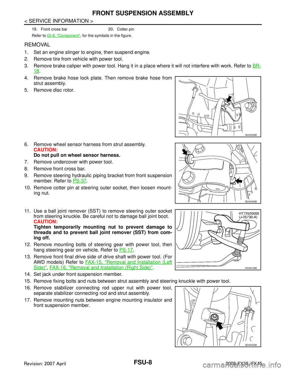
REMOVAL
1. Set an engine slinger to engine, then suspend engine.
2. Remove tire from vehicle with power tool.
3. Remove brake caliper with power tool. Hang it in a place where it will not interfere with work. Refer to BR-
18.
4. Remove brake hose lock plate. Then remove brake hose from strut assembly.
5. Remove disc rotor.
6. Remove wheel sensor harness from strut assembly. CAUTION:
Do not pull on wheel sensor harness.
7. Remove undercover with power tool.
8. Remove front cross bar.
9. Remove steering hydraulic piping bracket from front suspension member. Refer to PS-37
.
10. Remove cotter pin at steering outer socket, then loosen mount- ing nut.
11. Use a ball joint remover (SST) to remove steering outer socket from steering knuckle. Be careful not to damage ball joint boot.
CAUTION:
Tighten temporarily mounting nut to prevent damage to
threads and to prevent ball jo int remover (SST) from com-
ing off.
12. Remove mounting bolts of steering gear with power tool, then hang steering gear on vehicle. Refer to PS-17
.
13. Remove front final drive side of drive shaft with power tool. (For AWD models) Refer to FAX-15, "
Removal and Installation (Left
Side)", FAX-16, "Removal and Installation (Right Side)".
14. Set jack under front suspension member.
15. Remove fixing bolts and nuts between strut assembly and steering knuckle with power tool.
16. Remove stabilizer connecting rod upper nut with power tool, separate stabilizer connecting rod and strut assembly.
17. Remove mounting nuts between engine mounting insulator and front suspension member.
19. Front cross bar 20. Cotter pin
Refer to GI-8, "
Component", for the symbols in the figure.
SEIA0328E
SEIA0329E
PEIA0109E
SEIA0330E
3AA93ABC3ACD3AC03ACA3AC03AC63AC53A913A773A893A873A873A8E3A773A983AC73AC93AC03AC3
3A893A873A873A8F3A773A9D3AAF3A8A3A8C3A863A9D3AAF3A8B3A8C
Page 2854 of 3924
FSU-10
< SERVICE INFORMATION >
COIL SPRING AND STRUT
COIL SPRING AND STRUT
Removal and InstallationINFOID:0000000001327540
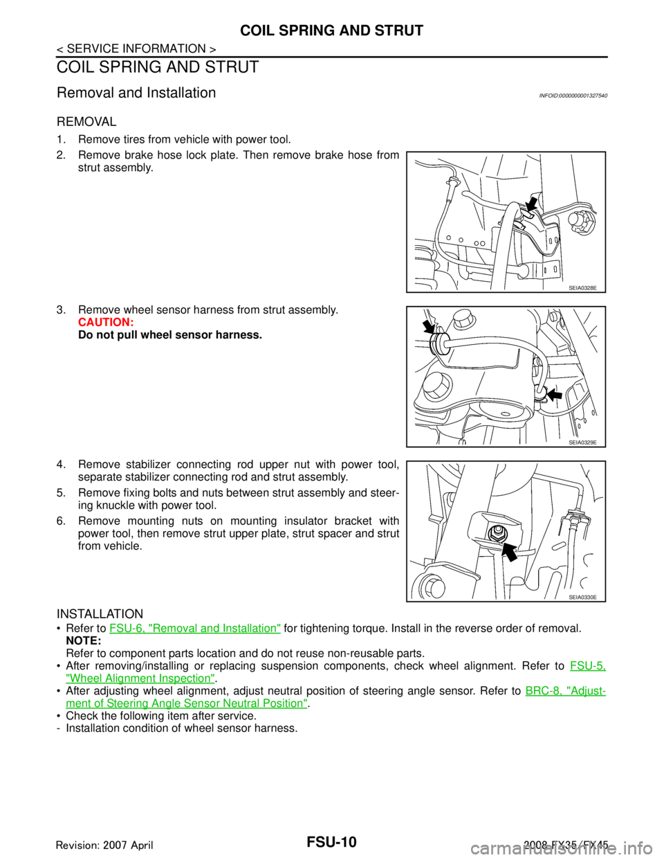
REMOVAL
1. Remove tires from vehicle with power tool.
2. Remove brake hose lock plate. Then remove brake hose fromstrut assembly.
3. Remove wheel sensor harness from strut assembly. CAUTION:
Do not pull wheel sensor harness.
4. Remove stabilizer connecting rod upper nut with power tool, separate stabilizer connecting rod and strut assembly.
5. Remove fixing bolts and nuts between strut assembly and steer- ing knuckle with power tool.
6. Remove mounting nuts on mounting insulator bracket with power tool, then remove strut upper plate, strut spacer and strut
from vehicle.
INSTALLATION
Refer to FSU-6, "Removal and Installation" for tightening torque. Install in the reverse order of removal.
NOTE:
Refer to component parts location and do not reuse non-reusable parts.
After removing/installing or replacing suspension components, check wheel alignment. Refer to FSU-5,
"Wheel Alignment Inspection".
After adjusting wheel alignment, adjust neutral position of steering angle sensor. Refer to BRC-8, "
Adjust-
ment of Steering Angle Sensor Neutral Position".
Check the following item after service.
- Installation condition of wheel sensor harness.
SEIA0328E
SEIA0329E
SEIA0330E
3AA93ABC3ACD3AC03ACA3AC03AC63AC53A913A773A893A873A873A8E3A773A983AC73AC93AC03AC3
3A893A873A873A8F3A773A9D3AAF3A8A3A8C3A863A9D3AAF3A8B3A8C
Page 2865 of 3924
PRECAUTIONSGI-3
< SERVICE INFORMATION >
C
DE
F
G H
I
J
K L
M B
GI
N
O P
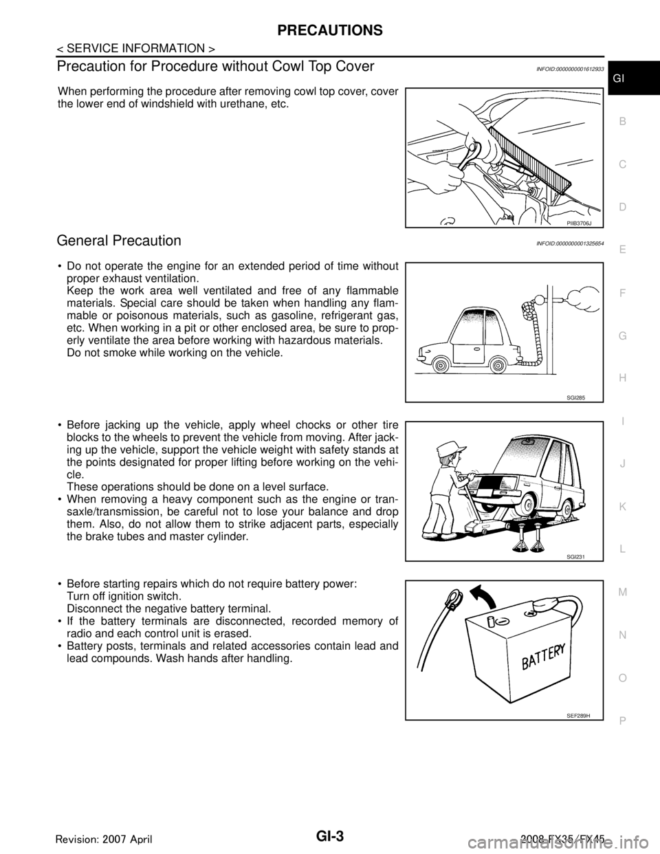
Precaution for Procedur e without Cowl Top CoverINFOID:0000000001612933
When performing the procedure after removing cowl top cover, cover
the lower end of windshield with urethane, etc.
General PrecautionINFOID:0000000001325654
Do not operate the engine for an extended period of time without
proper exhaust ventilation.
Keep the work area well ventilated and free of any flammable
materials. Special care should be taken when handling any flam-
mable or poisonous materials, such as gasoline, refrigerant gas,
etc. When working in a pit or ot her enclosed area, be sure to prop-
erly ventilate the area before working with hazardous materials.
Do not smoke while working on the vehicle.
Before jacking up the vehicle, apply wheel chocks or other tire
blocks to the wheels to prevent the vehicle from moving. After jack-
ing up the vehicle, support the vehicle weight with safety stands at
the points designated for proper lifting before working on the vehi-
cle.
These operations should be done on a level surface.
When removing a heavy component such as the engine or tran- saxle/transmission, be careful not to lose your balance and drop
them. Also, do not allow them to strike adjacent parts, especially
the brake tubes and master cylinder.
Before starting repairs which do not require battery power: Turn off ignition switch.
Disconnect the negative battery terminal.
If the battery terminals are disconnected, recorded memory of radio and each control unit is erased.
Battery posts, terminals and related accessories contain lead and
lead compounds. Wash hands after handling.
PIIB3706J
SGI285
SGI231
SEF289H
3AA93ABC3ACD3AC03ACA3AC03AC63AC53A913A773A893A873A873A8E3A773A983AC73AC93AC03AC3
3A893A873A873A8F3A773A9D3AAF3A8A3A8C3A863A9D3AAF3A8B3A8C
Page 2871 of 3924
HOW TO USE THIS MANUALGI-9
< SERVICE INFORMATION >
C
DE
F
G H
I
J
K L
M B
GI
N
O P
SYMBOLS
How to Follow Trouble DiagnosisINFOID:0000000001325668
DESCRIPTION
NOTICE:
Trouble diagnoses indicate work procedures required to diagnose problems effectively. Observe the following
instructions before diagnosing.
1. Before performing trouble diagno ses, read the “Preliminary Check” , the “Symptom Chart” or the
“Work Flow”.
2. After repairs, re-check that the prob lem has been completely eliminated.
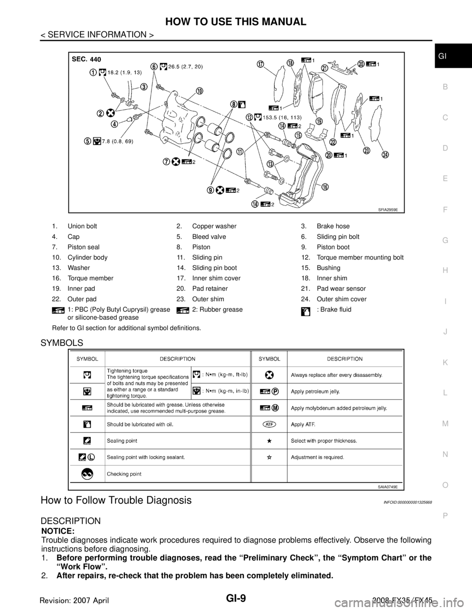
1. Union bolt 2. Copper washer 3. Brake hose
4. Cap 5. Bleed valve 6. Sliding pin bolt
7. Piston seal 8. Piston 9. Piston boot
10. Cylinder body 11. Sliding pin 12. Torque member mounting bolt
13. Washer 14. Sliding pin boot 15. Bushing
16. Torque member 17. Inner shim cover 18. Inner shim
19. Inner pad 20. Pad retainer 21. Pad wear sensor
22. Outer pad 23. Outer shim 24. Outer shim cover
1: PBC (Poly Butyl Cuprysil) grease
or silicone-based grease 2: Rubber grease : Brake fluid
Refer to GI section for additional symbol definitions.
SFIA2959E
SAIA0749E
3AA93ABC3ACD3AC03ACA3AC03AC63AC53A913A773A893A873A873A8E3A773A983AC73AC93AC03AC3
3A893A873A873A8F3A773A9D3AAF3A8A3A8C3A863A9D3AAF3A8B3A8C
Page 2880 of 3924
GI-18
< SERVICE INFORMATION >
HOW TO USE THIS MANUAL
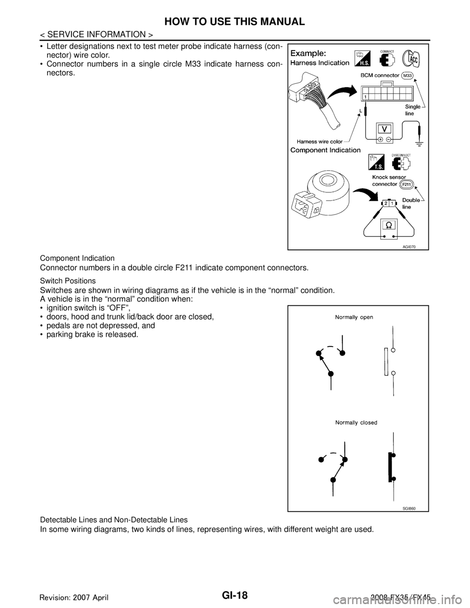
Letter designations next to test meter probe indicate harness (con-nector) wire color.
Connector numbers in a single circle M33 indicate harness con-
nectors.
Component Indication
Connector numbers in a double circle F211 indicate component connectors.
Switch Positions
Switches are shown in wiring diagrams as if the vehicle is in the “normal” condition.
A vehicle is in the “normal” condition when:
ignition switch is “OFF”,
doors, hood and trunk lid/back door are closed,
pedals are not depressed, and
parking brake is released.
Detectable Lines and Non-Detectable Lines
In some wiring diagrams, two kinds of lines, r epresenting wires, with different weight are used.
AGI070
SGI860
3AA93ABC3ACD3AC03ACA3AC03AC63AC53A913A773A893A873A873A8E3A773A983AC73AC93AC03AC3
3A893A873A873A8F3A773A9D3AAF3A8A3A8C3A863A9D3AAF3A8B3A8C
Page 2900 of 3924
GI-38
< SERVICE INFORMATION >
LIFTING POINT
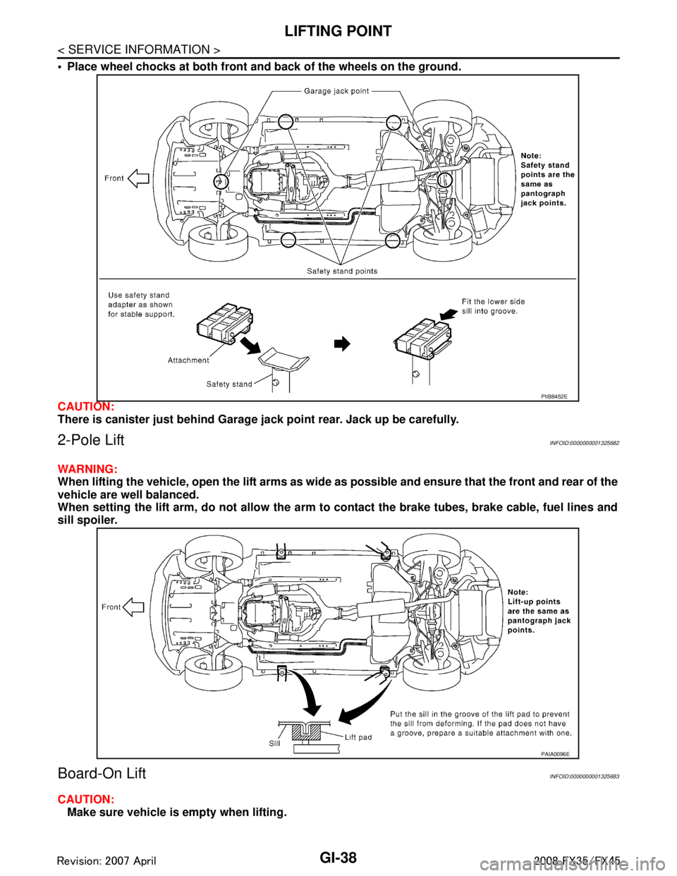
Place wheel chocks at both front and back of the wheels on the ground.
CAUTION:
There is canister just behind Garage jack point rear. Jack up be carefully.
2-Pole LiftINFOID:0000000001325682
WARNING:
When lifting the vehicle, open the lift arms as wide as possible and ensure that the front and rear of the
vehicle are well balanced.
When setting the lift arm, do no t allow the arm to contact the brake tubes, brake cable, fuel lines and
sill spoiler.
Board-On LiftINFOID:0000000001325683
CAUTION: Make sure vehicle is empty when lifting.
PIIB8452E
PAIA0096E
3AA93ABC3ACD3AC03ACA3AC03AC63AC53A913A773A893A873A873A8E3A773A983AC73AC93AC03AC3
3A893A873A873A8F3A773A9D3AAF3A8A3A8C3A863A9D3AAF3A8B3A8C