2008 INFINITI FX35 Brake
[x] Cancel search: BrakePage 3606 of 3924

SEAT BELTSSB-7
< SERVICE INFORMATION >
C
DE
F
G
I
J
K L
M A
B
SB
N
O P
7. Repeat steps above as necessary to check the other seat belts.
SEAT BELT RETRACTOR ON-VEHICLE INSPECTION
Emergency Locking Retractors (ELR) and Automatic Locking Retractors (ALR)
NOTE:
All seat belt retractors are of the Emergency Locki ng Retractors (ELR) type. In an emergency (sudden stop)
the retractor will lock and prevent the webbing from extending any further. All 3-point type seat belt retractors
except the driver's seat belt also have an Automati c Locking Retractors (ALR) mode. The ALR mode (also
called child restraint mode) is used when installing child seats. The ALR mode is activated when the seat belt
is fully extended. When the webbing is then retracted part ially, the ALR mode automatically locks the seat belt
in a specific position so the webbi ng cannot be extended any further. To c ancel the ALR mode, allow the seat
belt to fully wind back into the retractor.
Check the seat belt retractors using the following test(s ) to determine if a retractor assembly is operating prop-
erly.
Stationary Inspection for ELR Function
Grasp the shoulder webbing and pull forward quickly. The retractor should lock and prevent the belt from
extending further.
Stationary Inspection for ALR Function
1. Pull out entire length of seat belt from retractor until a click is heard.
2. Retract the webbing partially. A clicking noise should be heard as the webbing retracts indicating that the
retractor is in the Automatic Locking Retractor (ALR) mode.
3. Grasp the seat belt and try to pull out the retracto r. The webbing must lock and not extend any further. If
necessary replace the retractor assembly.
4. Allow the entire length of the webbing to retract to cancel the automatic locking mode.
Moving Inspection for ELR Function
WARNING:
Perform the following test in a safe, open area clear of other vehicles and obstructions (for example, a
large, empty parking lot). Road surface must be p aved and dry. DO NOT perform the following test on
wet or gravel roads or on public streets and highways. This could result in an accident and serious
personal injury. The driver and passenger must be prepared to brace themselves in the event the
retractor does not lock.
1. Fasten driver's seat belt. Buckle a passenger in to the seat for the belt that is to be tested.
2. Proceed to the designated safe area.
3. Drive the vehicle at approximately 16 km/h ( 10 MPH). Notify any passengers of a pending sudden stop.
The driver and passenger must be prepared to brace t hemselves in the event the retractor does not lock.
Apply brakes firmly and make a very hard stop.
During stop, seat belts should lock and not be extended. If the seat belt retractor assembly does not lock, per-
form the retractor off-vehicle inspection.
SEAT BELT RETRACTOR OFF-VEHICLE INSPECTION
1. Remove the seat belt retractor assembly.
3AA93ABC3ACD3AC03ACA3AC03AC63AC53A913A773A893A873A873A8E3A773A983AC73AC93AC03AC3
3A893A873A873A8F3A773A9D3AAF3A8A3A8C3A863A9D3AAF3A8B3A8C
Page 3799 of 3924

AWD SYSTEMTF-13
< SERVICE INFORMATION >
CEF
G H
I
J
K L
M A
B
TF
N
O P
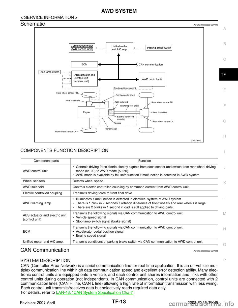
SchematicINFOID:0000000001327433
COMPONENTS FUNCTION DESCRIPTION
CAN CommunicationINFOID:0000000001327434
SYSTEM DESCRIPTION
CAN (Controller Area Network) is a serial communication li ne for real time application. It is an on-vehicle mul-
tiplex communication line with high data communication speed and excellent error detection ability. Many elec-
tronic control units are equipped onto a vehicle, and each control unit shares information and links with other
control units during operation (not independent). In CAN communication, control units are connected with 2
communication lines (CAN H line, CAN L line) allowing a high rate of information transmission with less wiring.
Each control unit transmits/receives data but selectively reads required data only.
For details, refer to LAN-43, "
CAN System Specification Chart".
SDIA2160E
Component parts Function
AWD control unit Controls driving force distribution by signals from each sensor and switch from rear wheel driving
mode (0:100) to AWD mode (50:50).
2WD mode is available by fail-safe function if malfunction is detected in AWD system.
Wheel sensors Detects wheel speed.
AWD solenoid Controls electric controlled coupling by command current from AWD control unit.
Electric controlled coupling Transmits driving force to front final drive.
AWD warning lamp Illuminates if malfunction is detected in electrical system of AWD system.
There is 1 blink in 2 seconds if rotation difference of front wheels and rear wheels is large.
There are 2 blinks in 1 second if load is still applied to driving parts.
ABS actuator and electric unit
(control unit) Transmits the following signals via CAN communication to AWD control unit.
Vehicle speed signal
Stop lamp switch signal (brake signal)
ECM Transmits the following signals via CAN communication to AWD control unit.
Accelerator pedal position signal
Engine speed signal
Unified meter and A/C amp. Transmits conditions of parking brake switch via CAN communication to AWD control unit.
3AA93ABC3ACD3AC03ACA3AC03AC63AC53A913A773A893A873A873A8E3A773A983AC73AC93AC03AC3
3A893A873A873A8F3A773A9D3AAF3A8A3A8C3A863A9D3AAF3A8B3A8C
Page 3807 of 3924

TROUBLE DIAGNOSISTF-21
< SERVICE INFORMATION >
CEF
G H
I
J
K L
M A
B
TF
N
O P
*: The values are changed by throttle opening and engine speed.
CONSULT-III Function (ALL MODE AWD/4WD)INFOID:0000000001327442
FUNCTION
CONSULT-III can display each diagnostic item using the diagnostic test modes shown following.
FR LH SENSOR [km/h] or [mph] Wheel speed (Front wheel
left)Vehicle stopped 0.00 km/h (0.00 mph)
Vehicle running
CAUTION:
Check air pressure of tire under
standard condition.
Approximately equal to
the indication on speed-
ometer (Inside of
±10%)
RR RH SENSOR [km/h] or [mph] Wheel speed (Rear wheel
right)Vehicle stopped 0.00 km/h (0.00 mph)
Vehicle running
CAUTION:
Check air pressure of tire under
standard condition.
Approximately equal to
the indication on speed-
ometer (Inside of
±10%)
RR LH SENSOR [km/h] or [mph] Wheel speed (Rear wheel left) Vehicle stopped 0.00 km/h (0.00 mph)
Vehicle running
CAUTION:
Check air pressure of tire under
standard condition.Approximately equal to
the indication on speed-
ometer (Inside of
±10%)
BATTERY VOLT [V] Power supply voltage for AWD
control unitIgnition switch: ON Battery voltage
THRTL POS SEN [%] Throttle opening condition When depressing accelerator pedal
(Value rises gradually in response to
throttle position.)0 - 100%
ETS SOLENOID [A] Monitored value of current at
AWD solenoidEngine running
At idle speed
Approx. 0.000A
Engine running
When depressing accelerator ped- al Approx. 0.000 - 2.400A*
STOP LAMP SW [ON/OFF] Condition of brake pedal oper-
ationBrake pedal: Depressed ON
Brake pedal: Released OFF
ENG SPEED SIG [RUN/STOP] Condi tion of engine runningEngine stopped
(Engine speed: Less than 400 rpm)
STOP
Engine running
(Engine speed: 400 rpm or more) RUN
ETS ACTUATOR [ON/OFF] Operating condition of AWD
actuator relay (integrated in
AWD control unit)Engine stopped (Ignition
switch: ON)
OFF
Engine running ON
4WD WARN LAMP [ON/OFF] AWD warning lamp conditionAWD warning lamp: ON ON
AWD warning lamp: OFF OFF
4WD MODE MON [AUTO] Control status of AWD Engine running AUTO
DIS-TIRE MONI [mm] Improper size tire installed
conditionVehicle running with normal size tire
installed
0-4 mm
Vehicle running with improper size
tire installed (Front /rear tire size dif-
ference, wear condition) 4-8 mm, 8- mm
P BRAKE SW [ON/OFF] Condition of parking brake Parking brake operated ON
Parking brake not operated OFF
Monitored item [Unit] Content Condition Display value
3AA93ABC3ACD3AC03ACA3AC03AC63AC53A913A773A893A873A873A8E3A773A983AC73AC93AC03AC3
3A893A873A873A8F3A773A9D3AAF3A8A3A8C3A863A9D3AAF3A8B3A8C
Page 3809 of 3924

TROUBLE DIAGNOSISTF-23
< SERVICE INFORMATION >
CEF
G H
I
J
K L
M A
B
TF
N
O P
× : Standard : Not applicable
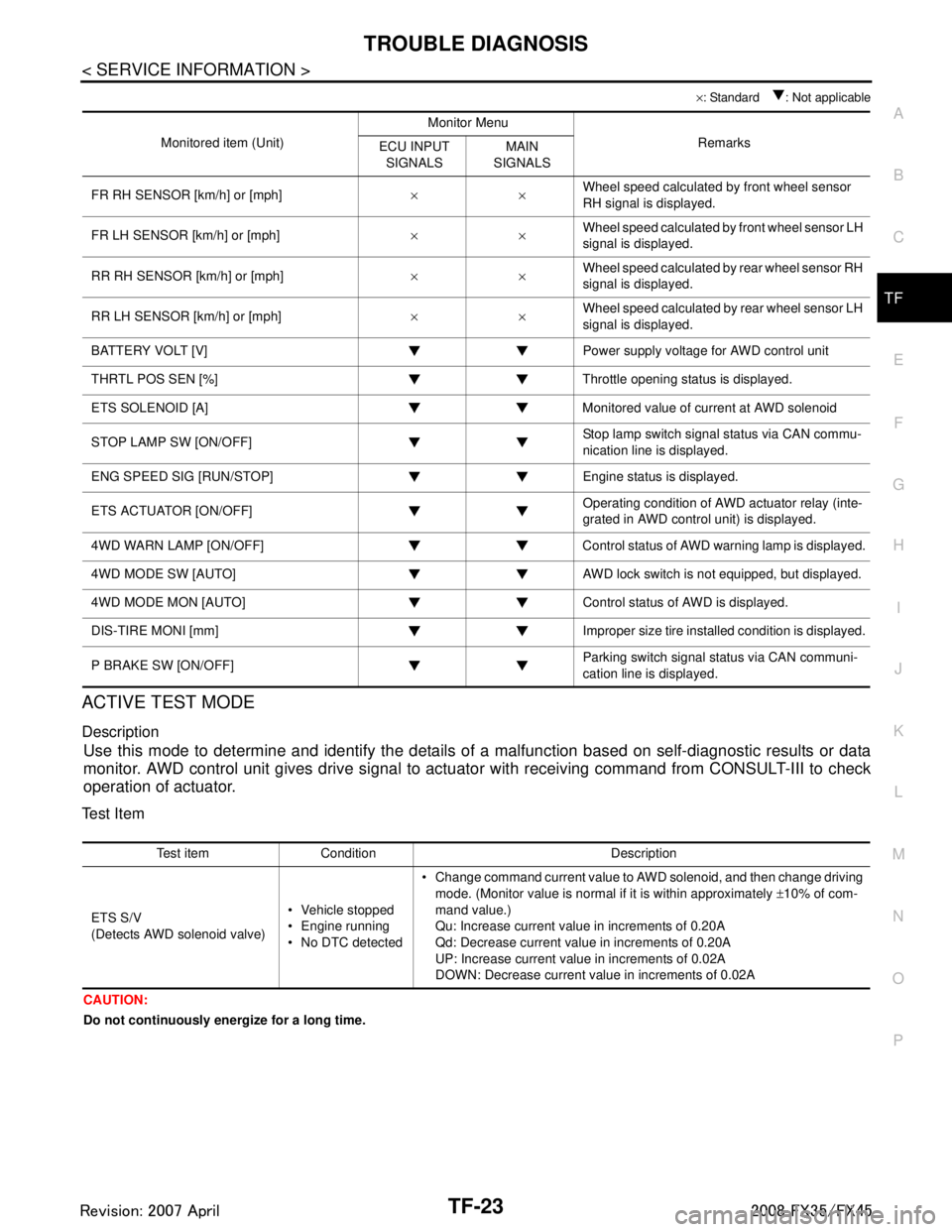
ACTIVE TEST MODE
Description
Use this mode to determine and identify the details of a malfunction based on self-diagnostic results or data
monitor. AWD control unit gives drive signal to actuat or with receiving command from CONSULT-III to check
operation of actuator.
Test Item
CAUTION:
Do not continuously energize for a long time.
Monitored item (Unit) Monitor Menu
Remarks
ECU INPUT
SIGNALS MAIN
SIGNALS
FR RH SENSOR [km/h] or [mph] ××Wheel speed calculated by front wheel sensor
RH signal is displayed.
FR LH SENSOR [km/h] or [mph] ××Wheel speed calculated by front wheel sensor LH
signal is displayed.
RR RH SENSOR [km/h] or [mph] ××Wheel speed calculated by rear wheel sensor RH
signal is displayed.
RR LH SENSOR [km/h] or [mph] ××Wheel speed calculated by rear wheel sensor LH
signal is displayed.
BATTERY VOLT [V] Power supply voltage for AWD control unit
THRTL POS SEN [%] Throttle opening status is displayed.
ETS SOLENOID [A] Monitored value of current at AWD solenoid
STOP LAMP SW [ON/OFF] Stop lamp switch signal status via CAN commu-
nication line is displayed.
ENG SPEED SIG [RUN/STOP] Eng ine status is displayed.
ETS ACTUATOR [ON/OFF] Operating condition of AWD actuator relay (inte-
grated in AWD control unit) is displayed.
4WD WARN LAMP [ON/OFF] Control status of AWD warning lamp is displayed.
4WD MODE SW [AUTO] AWD lock switch is not equipped, but displayed.
4WD MODE MON [AUTO] Control status of AWD is displayed.
DIS-TIRE MONI [mm] Improper size tire installed condition is displayed.
P BRAKE SW [ON/OFF] Parking switch signal status via CAN communi-
cation line is displayed.
Test item Condition Description
ETS S/V
(Detects AWD solenoid valve) Vehicle stopped
Engine running
No DTC detected Change command current value to AWD solenoid, and then change driving
mode. (Monitor value is normal if it is within approximately ±10% of com-
mand value.)
Qu: Increase current value in increments of 0.20A
Qd: Decrease current value in increments of 0.20A
UP: Increase current value in increments of 0.02A
DOWN: Decrease current value in increments of 0.02A
3AA93ABC3ACD3AC03ACA3AC03AC63AC53A913A773A893A873A873A8E3A773A983AC73AC93AC03AC3
3A893A873A873A8F3A773A9D3AAF3A8A3A8C3A863A9D3AAF3A8B3A8C
Page 3818 of 3924

TF-32
< SERVICE INFORMATION >
TROUBLE DIAGNOSIS FOR SYMPTOMS
3. Start the engine, and then make sure that “4WD W/L” display turns from “ON” to “OFF” after several sec-
onds.
OK or NG
OK >> GO TO 6.
NG >> Perform trouble diagnosis for combination meter. Refer to DI-15, "
Trouble Diagnosis".
6.SYMPTOM CHECK
Check again.
OK or NG
OK >> INSPECTION END
NG >> Replace unified meter control unit assembly. Refer to DI-23, "
Disassembly and Assembly of Com-
bination Meter".
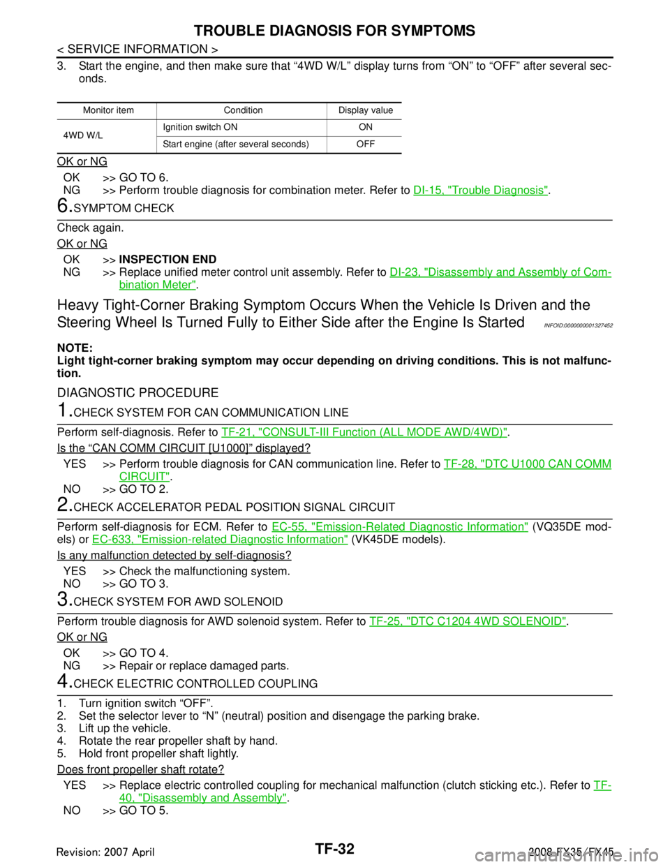
Heavy Tight-Corner Braking Symptom Occurs When the Vehicle Is Driven and the
Steering Wheel Is Turned Fu lly to Either Side after the Engine Is Started
INFOID:0000000001327452
NOTE:
Light tight-corner braking symptom may occur depending on driving conditions. This is not malfunc-
tion.
DIAGNOSTIC PROCEDURE
1.CHECK SYSTEM FOR CAN COMMUNICATION LINE
Perform self-diagnosis. Refer to TF-21, "
CONSULT-III Function (ALL MODE AWD/4WD)".
Is the
“CAN COMM CIRCUIT [U1000]” displayed?
YES >> Perform trouble diagnosis for CAN communication line. Refer to TF-28, "DTC U1000 CAN COMM
CIRCUIT".
NO >> GO TO 2.
2.CHECK ACCELERATOR PEDAL POSITION SIGNAL CIRCUIT
Perform self-diagnosis for ECM. Refer to EC-55, "
Emission-Related Diagnostic Information" (VQ35DE mod-
els) or EC-633, "
Emission-related Diagnostic Information" (VK45DE models).
Is any malfunction detec ted by self-diagnosis?
YES >> Check the malfunctioning system.
NO >> GO TO 3.
3.CHECK SYSTEM FOR AWD SOLENOID
Perform trouble diagnosis for AWD solenoid system. Refer to TF-25, "
DTC C1204 4WD SOLENOID".
OK or NG
OK >> GO TO 4.
NG >> Repair or replace damaged parts.
4.CHECK ELECTRIC CONTROLLED COUPLING
1. Turn ignition switch “OFF”.
2. Set the selector lever to “N” (neutral) position and disengage the parking brake.
3. Lift up the vehicle.
4. Rotate the rear propeller shaft by hand.
5. Hold front propeller shaft lightly.
Does front propeller shaft rotate?
YES >> Replace electric controlled coupling for mec hanical malfunction (clutch sticking etc.). Refer to TF-
40, "Disassembly and Assembly".
NO >> GO TO 5.
Monitor item Condition Display value
4WD W/L Ignition switch ON ON
Start engine (after several seconds) OFF
3AA93ABC3ACD3AC03ACA3AC03AC63AC53A913A773A893A873A873A8E3A773A983AC73AC93AC03AC3
3A893A873A873A8F3A773A9D3AAF3A8A3A8C3A863A9D3AAF3A8B3A8C
Page 3846 of 3924

WT-6
< SERVICE INFORMATION >
NOISE, VIBRATION AND HARSHNESS (NVH) TROUBLESHOOTING
NOISE, VIBRATION AND HARSHNESS (NVH) TROUBLESHOOTING
NVH Troubleshooting ChartINFOID:0000000001327572
Use the chart below to help you find the cause of the sy mptom. If necessary, repair or replace these parts.
×: Applicable
Reference
FAX-4
,
FAX-11
, FSU-5
WT-7WT-8WT-35WT-9—
—
WT-35
NVH in PR section
NVH in RFD section
NVH in FAX and FSU section
NVH in RAX and RSU section Refer to TIRE in this chart.
Refer to ROAD WHEEL in this chart. NVH in FAX, RAX sectionNVH in BR section
NVH in PS section
Possible cause an d SUSPECTED PARTS
Improper installation, looseness
Out-of-round
Unbalance
Incorrect tire pressure
Uneven tire wear
Deformation or damage
Non-uniformity
Incorrect tire size
PROPELLER SHAFT
DIFFERENTIAL
FRONT AXLE AND FRONT SUSPENSION
REAR AXLE AND REAR SUSPENSION
TIRE
ROAD WHEEL
DRIVE SHAFT
BRAKE
STEERING
SymptomTIRE Noise
× ×××××× ×××× ××××
Shake ××××××××××××××
Vibration ×××××××
Shimmy × ××××××× ×× × ××
Judder ××××××× ×××××
Poor quality ride
or handling × ××××× × ×× ×
ROAD WHEEL Noise
× ×× × ××××× ×××
Shake × ×× × × ××× ×××
Shimmy, Judder ×××× ×××××
Poor quality ride
or handling ××× × ×××
3AA93ABC3ACD3AC03ACA3AC03AC63AC53A913A773A893A873A873A8E3A773A983AC73AC93AC03AC3
3A893A873A873A8F3A773A9D3AAF3A8A3A8C3A863A9D3AAF3A8B3A8C