2008 INFINITI FX35 Brake
[x] Cancel search: BrakePage 3363 of 3924
PB-8
< SERVICE INFORMATION >
PARKING BRAKE SHOE
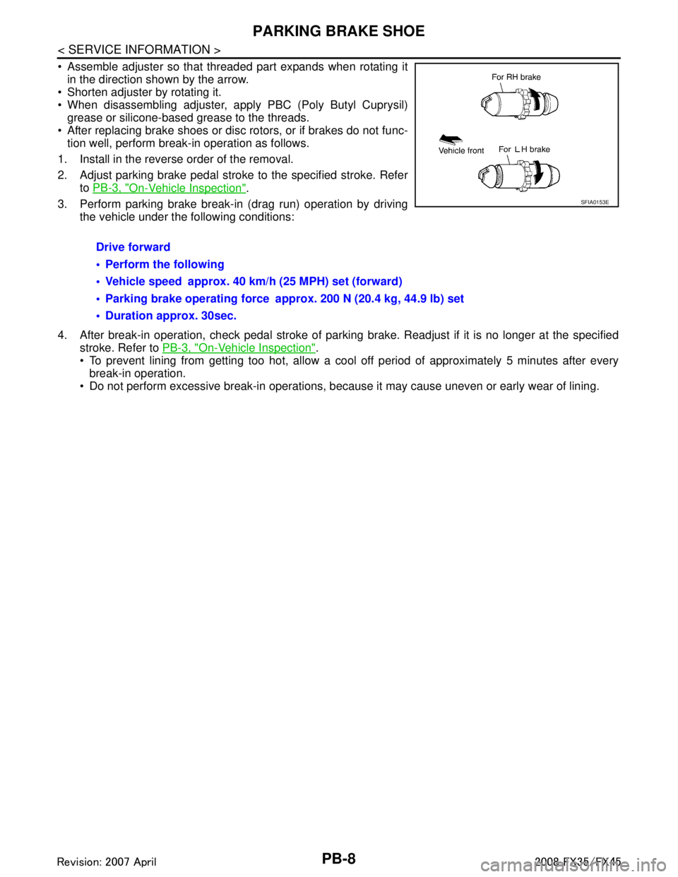
Assemble adjuster so that threaded part expands when rotating itin the direction shown by the arrow.
Shorten adjuster by rotating it.
When disassembling adjuster, apply PBC (Poly Butyl Cuprysil)
grease or silicone-based grease to the threads.
After replacing brake shoes or disc rotors, or if brakes do not func-
tion well, perform break-in operation as follows.
1. Install in the reverse order of the removal.
2. Adjust parking brake pedal stroke to the specified stroke. Refer to PB-3, "
On-Vehicle Inspection".
3. Perform parking brake break-in (drag run) operation by driving the vehicle under the following conditions:
4. After break-in operation, check pedal stroke of parking brake. Readjust if it is no longer at the specified
stroke. Refer to PB-3, "
On-Vehicle Inspection".
To prevent lining from getting too hot, allow a cool off period of approximately 5 minutes after every
break-in operation.
Do not perform excessive break-in operations, becaus e it may cause uneven or early wear of lining.
Drive forward
Perform the following
Vehicle speed approx. 40 km/h (25 MPH) set (forward)
Parking brake operating force approx. 200 N (20.4 kg, 44.9 lb) set
Duration approx. 30sec.
SFIA0153E
3AA93ABC3ACD3AC03ACA3AC03AC63AC53A913A773A893A873A873A8E3A773A983AC73AC93AC03AC3
3A893A873A873A8F3A773A9D3AAF3A8A3A8C3A863A9D3AAF3A8B3A8C
Page 3364 of 3924

SERVICE DATA AND SPECIFICATIONS (SDS)
PB-9
< SERVICE INFORMATION >
C
D E
G H
I
J
K L
M A
B
PB
N
O P
SERVICE DATA AND SPECIFICATIONS (SDS)
Parking Drum BrakeINFOID:0000000001327651
Parking Brake ControlINFOID:0000000001327652
Brake lining Standard thickness 3.2 mm (0.126 in)
Repair limit thickness 1.5 mm (0.059 in)
Drum (disc) Standard inner diameter 190 mm (7.48 in) dia.
Maximum inner diameter 191 mm (7.52 in) dia.
Control type
Foot pedal type
Number of notches [under a force of 200 N (20.4 kg, 44.9 lb)] 4 − 5 notches
Number of notches when brake warning lamp comes on 1 notch
3AA93ABC3ACD3AC03ACA3AC03AC63AC53A913A773A893A873A873A8E3A773A983AC73AC93AC03AC3
3A893A873A873A8F3A773A9D3AAF3A8A3A8C3A863A9D3AAF3A8B3A8C
Page 3425 of 3924

HARNESSPG-61
< SERVICE INFORMATION >
C
DE
F
G H
I
J
L
M A
B
PG
N
O P
Code Section Wiring Diagram Name
A/C ATC Air Conditioner
AF1B1 EC Air Fuel Ratio Sensor 1 Bank 1
AF1B2 EC Air Fuel Ratio Sensor 1 Bank 2
AF1HB1 EC Air Fuel Ratio Sensor 1 Heater Bank 1
AF1HB2 EC Air Fuel Ratio Sensor 1 Heater Bank 2
APPS1 EC Accelerator Pedal Position Sensor
APPS2 EC Accelerator Pedal Position Sensor
APPS3 EC Accelerator Pedal Position Sensor
ASC/BS EC Automatic Speed Control Device (ASCD) Brake Switch
ASC/SW EC Automatic Speed Control Device (ASCD) Steering Switch
ASCBOF EC Automatic Speed Control Device (ASCD) Brake Switch
ASCIND EC Automatic Speed Contro l Device (ASCD) Indicator
AT/IND DI A/T Indicator Lamp
AUDIO AV Audio
AUT/DP SE Automatic Drive Positioner
AUTO/L LT Automatic Light System
AWD TF AWD Control System
B/CLOS BL Back Door Closure System
BACK/L LT Back-Up Lamp
BRK/SW EC Brake Switch
CAN AT CAN Communication Line
CAN EC CAN Communication Line
CAN LAN CAN System
CHARGE SC Charging System
CHIME DI Warning Chime
CLOCK DI Clock
COMBSW LT Combination Switch
COMM AV Audio Visual Communication Line
COMPAS DI Compass
COOL/F EC Cooling Fan Control
D/LOCK BL Power Door Lock
DEF GW Rear Window Defogger
DTRL LT Headlamp - With Daytime Light System
ECM/PW EC ECM Power Supply for Back-Up
ECTS EC Engine Coolant Temperature Sensor
ETC1 EC Electric Throttle Control Function
ETC2 EC Electric Throttle Control Motor Relay
ETC3 EC Electric Throttle Control Motor
F/FOG LT Front Fog Lamp
F/PUMP EC Fuel Pump
FTS AT A/T Fluid Temperature Sensor Circuit
FTTS EC Fuel Tank Temperature Sensor
FUELB1 EC Fuel Injection System Function (Bank 1)
FUELB2 EC Fuel Injection System Function (Bank 2)
3AA93ABC3ACD3AC03ACA3AC03AC63AC53A913A773A893A873A873A8E3A773A983AC73AC93AC03AC3
3A893A873A873A8F3A773A9D3AAF3A8A3A8C3A863A9D3AAF3A8B3A8C
Page 3426 of 3924

PG-62
< SERVICE INFORMATION >
HARNESS
H/AIM LT Headlamp Aiming Control System
H/LAMP LT Headlamp
H/PHON AV Hands Free Telephone
HORN WW Horn
HSEAT SE Heated Seat
I/KEY BL Intelligent Key System
I/MIRR GW Inside Mirror (Auto Anti-Dazzling Mirror)
IATS EC Intake Air Temperature Sensor
ICC ACS Intelligent Cruise Control System
ICC/BS EC ICC Brake Switch
ICC/SW EC ICC Steering Switch
ICCBOF EC ICC Brake Switch
IGNSYS EC Ignition System
ILL LT Illumination
INF/D AV Vehicle Information and Integrated Switch System
INJECT EC Injector
IVCB1 EC Intake Valve Timing Control Solenoid Valve Bank 1
IVCB2 EC Intake Valve Timing Control Solenoid Valve Bank 2
IVCSB1 EC Intake Valve Timing Control Position Sensor Bank 1
IVCSB2 EC Intake Valve Timing Control Position Sensor Bank 2
IVTB1 EC Intake Valve Timing Control System (Bank 1)
IVTB2 EC Intake Valve Timing Control System (Bank 2)
KEYLES BL Remote Keyless Entry System
KS EC Knock Sensor
LDW DI Lane Departure Warning System
M/ANT AV Manual Antenna
MAFS EC Mass Air Flow Sensor
MAIN AT Main Power Supply and Ground Circuit
MAIN EC Main Power Supply and Ground Circuit
MES AV Mobile Entertainment System
METER DI Speedometer, Tachometer, Temp. and Fuel Gauges
MIL/DL EC MIL & Data Link Connector
MIRROR GW Power Door Mirror
MMSW AT Manual Mode Switch
NATS BL Nissan Anti-Theft System
NAVI AV Navigation System
NONDTC AT Non-Detective Items
O2H2B1 EC Heated Oxygen Sensor 2 Heater Bank 1
O2H2B2 EC Heated Oxygen Sensor 2 Heater Bank 2
O2S2B1 EC Heated Oxygen Sensor 2 Bank 1
O2S2B2 EC Heated Oxygen Sensor 2 Bank 2
P/SCKT WW Power Socket
PGC/V EC EVAP Canister Purge Volume Control Solenoid Valve
PHASE EC Camshaft Position Sensor (PHASE) Code Section Wiri
ng Diagram Name
3AA93ABC3ACD3AC03ACA3AC03AC63AC53A913A773A893A873A873A8E3A773A983AC73AC93AC03AC3
3A893A873A873A8F3A773A9D3AAF3A8A3A8C3A863A9D3AAF3A8B3A8C
Page 3445 of 3924
NOISE, VIBRATION AND HARSHNESS (NVH) TROUBLESHOOTINGPR-3
< SERVICE INFORMATION >
CEF
G H
I
J
K L
M A
B
PR
N
O P
NOISE, VIBRATION AND HARSHN ESS (NVH) TROUBLESHOOTING
NVH Troubleshooting ChartINFOID:0000000001327465
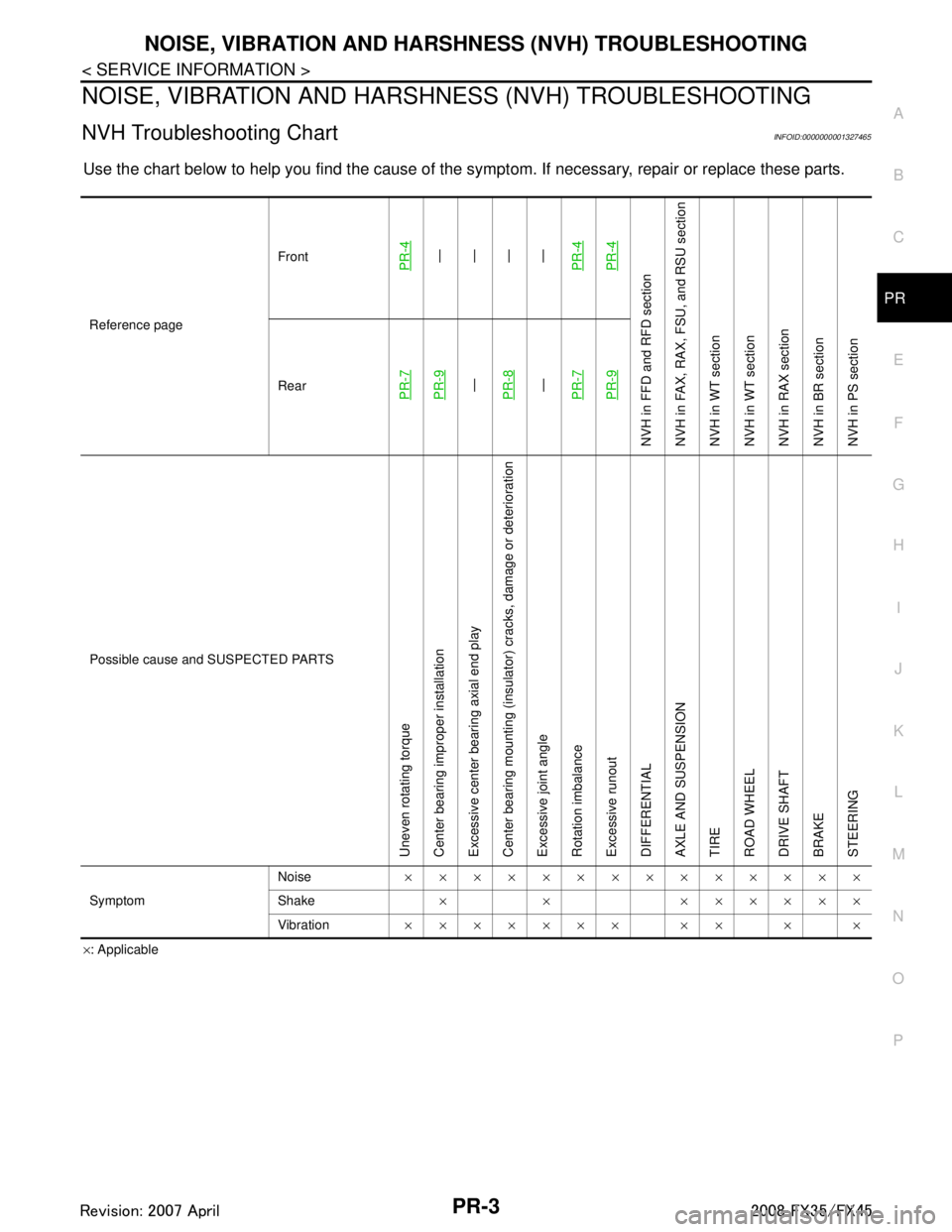
Use the chart below to help you find t he cause of the symptom. If necessary, repair or replace these parts.
×: Applicable
Reference page
Front
PR-4—
—
—
—
PR-4PR-4
NVH in FFD an d RFD section
NVH in FAX, RAX, FS U, and RSU section
NVH in WT section
NVH in WT section
NVH in RAX section
NVH in BR section
NVH in PS section
RearPR-7PR-9—
PR-8—
PR-7PR-9
Possible cause and SUSPECTED PARTS
Uneven rotating torque
Center bearing improper installation
Excessive center bearing axial end play
Center bearing mounting (insulator) cracks, damage or deterioration
Excessive joint angle
Rotation imbalance
Excessive runout
DIFFERENTIAL
AXLE AND SUSPENSION
TIRE
ROAD WHEEL
DRIVE SHAFT
BRAKE
STEERING
Symptom Noise
××××××××××××××
Shake × × ××××××
Vibration ××××××× ×× × ×
3AA93ABC3ACD3AC03ACA3AC03AC63AC53A913A773A893A873A873A8E3A773A983AC73AC93AC03AC3
3A893A873A873A8F3A773A9D3AAF3A8A3A8C3A863A9D3AAF3A8B3A8C
Page 3451 of 3924
REAR PROPELLER SHAFTPR-9
< SERVICE INFORMATION >
CEF
G H
I
J
K L
M A
B
PR
N
O P
Removal and InstallationINFOID:0000000001327471
REMOVAL
1. Move the A/T select lever to N position and release the parking brake.
2. Remove the tunnel stay with power tool. Refer to RSU-5
.
3. Remove the center muffler with power tool. Refer to EX-3
.
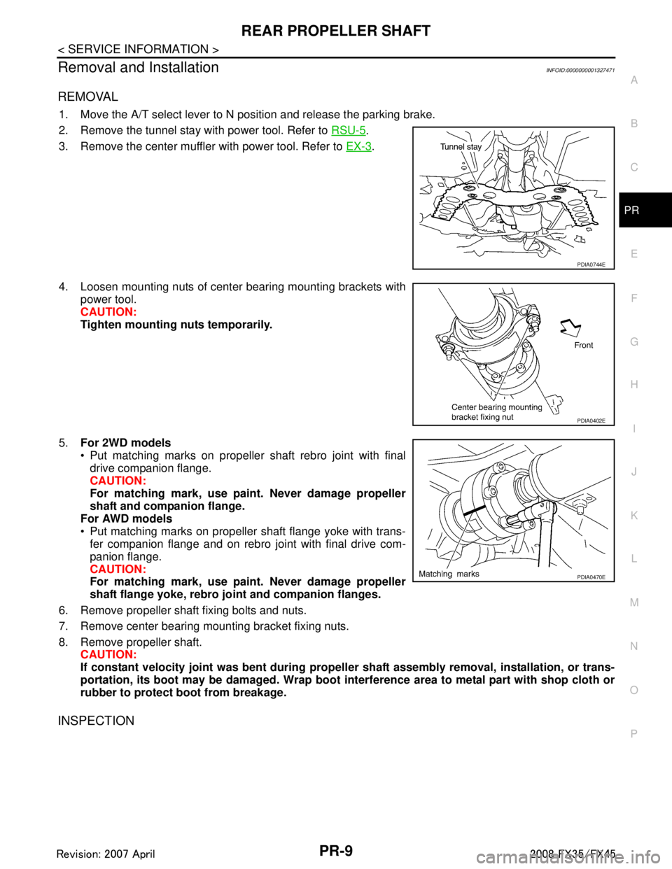
4. Loosen mounting nuts of center bearing mounting brackets with power tool.
CAUTION:
Tighten mounting nuts temporarily.
5. For 2WD models
Put matching marks on propeller shaft rebro joint with final
drive companion flange.
CAUTION:
For matching mark, use paint. Never damage propeller
shaft and companion flange.
For AWD models
Put matching marks on propeller shaft flange yoke with trans- fer companion flange and on rebro joint with final drive com-
panion flange.
CAUTION:
For matching mark, use paint. Never damage propeller
shaft flange yoke, rebro jo int and companion flanges.
6. Remove propeller shaft fixing bolts and nuts.
7. Remove center bearing mounting bracket fixing nuts.
8. Remove propeller shaft. CAUTION:
If constant velocity joint was bent during prop eller shaft assembly removal, installation, or trans-
portation, its boot may be damaged. Wrap boot interference area to metal part with shop cloth or
rubber to protect boot from breakage.
INSPECTION
PDIA0744E
PDIA0402E
PDIA0470E
3AA93ABC3ACD3AC03ACA3AC03AC63AC53A913A773A893A873A873A8E3A773A983AC73AC93AC03AC3
3A893A873A873A8F3A773A9D3AAF3A8A3A8C3A863A9D3AAF3A8B3A8C
Page 3461 of 3924
PS-6
< SERVICE INFORMATION >
NOISE, VIBRATION AND HARSHNESS (NVH) TROUBLESHOOTING
NOISE, VIBRATION AND HARSHNESS (NVH) TROUBLESHOOTING
NVH Troubleshooting ChartINFOID:0000000001327708
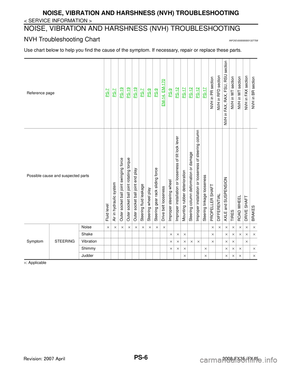
Use chart below to help you find the cause of the symp tom. If necessary, repair or replace these parts.
×: ApplicableReference page
PS-7PS-7PS-19PS-19PS-19PS-7PS-9PS-9
EM-14
,
EM-170PS-9PS-12PS-17PS-12PS-12PS-17
NVH in PR section
NVH in RFD section
NVH in FAX, RAX, FSU, RSU section NVH in WT section
NVH in WT section
NVH in FAX section
NVH in BR section
Possible cause and suspected parts
Fluid level
Air in hydraulic system
Outer socket ball joint swinging force
Outer socket ball joint rotating torque
Outer socket ball joint end play
Steering fluid leakage
Steering wheel play
Steering gear rack sliding force
Drive belt looseness
Improper steering wheel
Improper installation or looseness of tilt lock lever
Mounting rubber deterioration
Steering column deformation or damage
Improper installation or looseness of steering column
Steering linkage looseness
PROPELLER SHAFT
DIFFERENTIAL
AXLE and SUSPENSION
TIRES
ROAD WHEEL
DRIVE SHAFT
BRAKES
Symptom STEERING Noise
× × ××××× × × ×××××× ×
Shake ××× × ×××× ×
Vibration ××××× × ×× ×
Shimmy ××× × ××× ×
Judder ××××××
3AA93ABC3ACD3AC03ACA3AC03AC63AC53A913A773A893A873A873A8E3A773A983AC73AC93AC03AC3
3A893A873A873A8F3A773A9D3AAF3A8A3A8C3A863A9D3AAF3A8B3A8C
Page 3464 of 3924
STEERING WHEELPS-9
< SERVICE INFORMATION >
C
DE
F
H I
J
K L
M A
B
PS
N
O P
STEERING WHEEL
On-Vehicle Inspection and ServiceINFOID:0000000001327712
CHECKING CONDITION OF INSTALLATION
Check installation condition of steering gear assemb ly, front suspension, axle and steering column.
Check if movement exists when steering wheel is mo ved up and down, to the left and right and to the axial
direction.
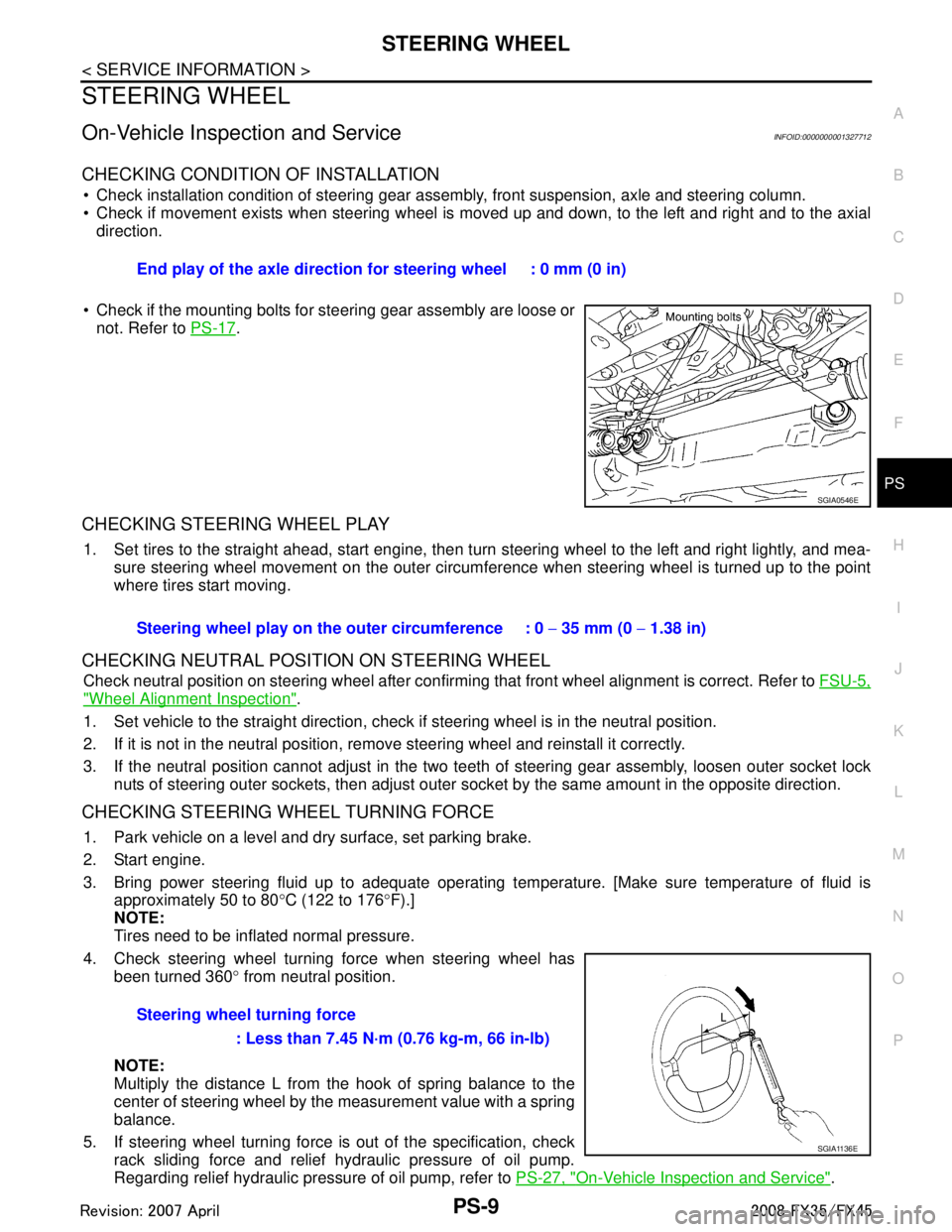
Check if the mounting bolts for steering gear assembly are loose or not. Refer to PS-17
.
CHECKING STEERING WHEEL PLAY
1. Set tires to the straight ahead, start engine, then turn steering wheel to the left and right lightly, and mea-
sure steering wheel movement on the outer circumfe rence when steering wheel is turned up to the point
where tires start moving.
CHECKING NEUTRAL POSITION ON STEERING WHEEL
Check neutral position on steering wheel after confirming that front wheel alignment is correct. Refer to FSU-5,
"Wheel Alignment Inspection".
1. Set vehicle to the straight direction, chec k if steering wheel is in the neutral position.
2. If it is not in the neutral position, remo ve steering wheel and reinstall it correctly.
3. If the neutral position cannot adjust in the two teeth of steering gear assembly, loosen outer socket lock
nuts of steering outer sockets, then adjust outer so cket by the same amount in the opposite direction.
CHECKING STEERING WHEEL TURNING FORCE
1. Park vehicle on a level and dry surface, set parking brake.
2. Start engine.
3. Bring power steering fluid up to adequate operating te mperature. [Make sure temperature of fluid is
approximately 50 to 80 °C (122 to 176 °F).]
NOTE:
Tires need to be inflated normal pressure.
4. Check steering wheel turning force when steering wheel has been turned 360 ° from neutral position.
NOTE:
Multiply the distance L from the hook of spring balance to the
center of steering wheel by the measurement value with a spring
balance.
5. If steering wheel turning force is out of the specification, check
rack sliding force and relief hydraulic pressure of oil pump.
Regarding relief hydraulic pressure of oil pump, refer to PS-27, "
On-Vehicle Inspection and Service".
End play of the axle direction for steering wheel : 0 mm (0 in)
SGIA0546E
Steering wheel play on the
outer circumference : 0 − 35 mm (0 − 1.38 in)
Steering wheel turning force : Less than 7.45 N·m (0.76 kg-m, 66 in-lb)
SGIA1136E
3AA93ABC3ACD3AC03ACA3AC03AC63AC53A913A773A893A873A873A8E3A773A983AC73AC93AC03AC3
3A893A873A873A8F3A773A9D3AAF3A8A3A8C3A863A9D3AAF3A8B3A8C