Page 2765 of 3924

EXHAUST SYSTEMEX-5
< SERVICE INFORMATION >
C
DE
F
G H
I
J
K L
M A
EX
NP
O
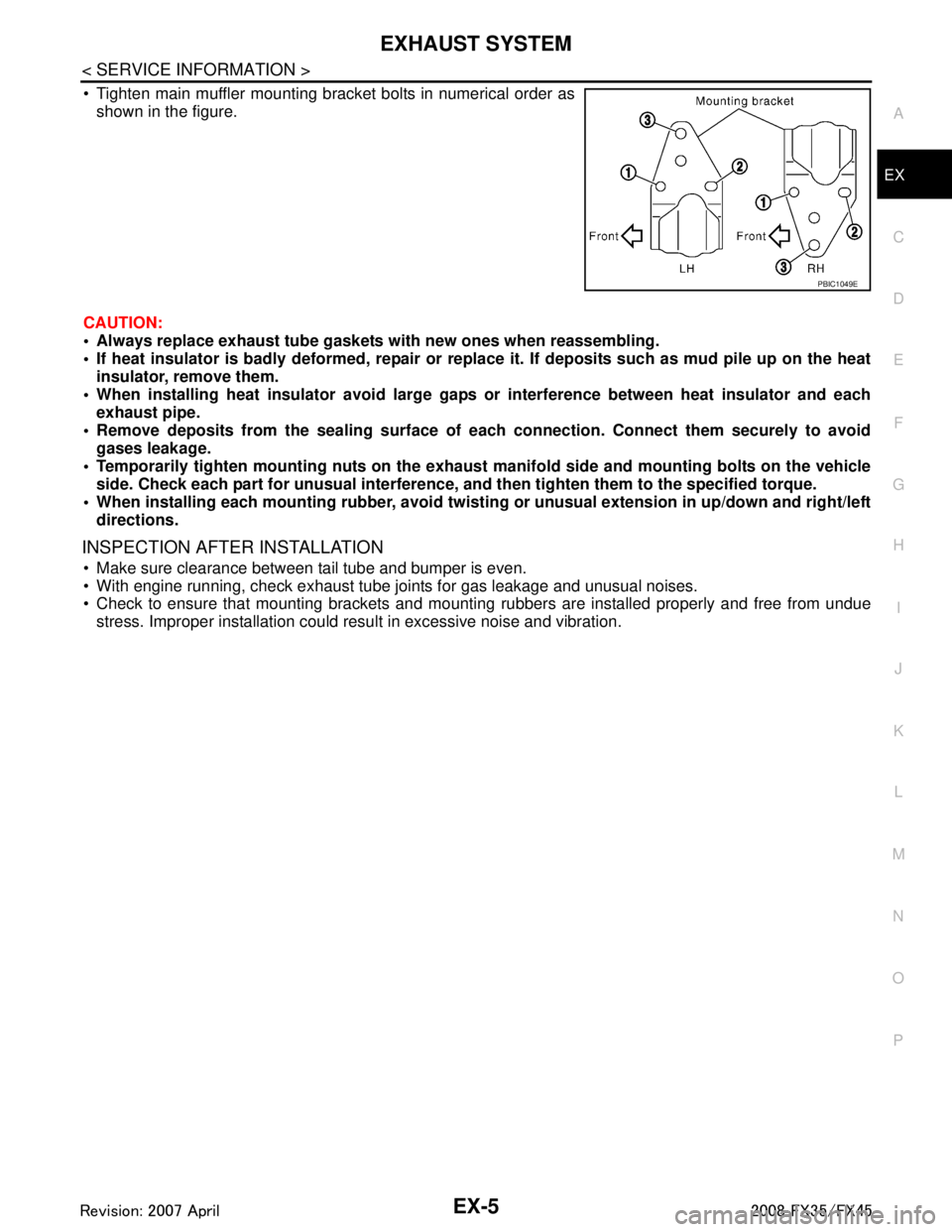
Tighten main muffler mounting bracket bolts in numerical order as
shown in the figure.
CAUTION:
Always replace exhaust tube gasket s with new ones when reassembling.
If heat insulator is badly deformed, repair or repl ace it. If deposits such as mud pile up on the heat
insulator, remove them.
When installing heat insulator avoid large gaps or interference between heat insulator and each
exhaust pipe.
Remove deposits from the sealing surface of each connection. Connect them securely to avoid
gases leakage.
Temporarily tighten mounting nuts on the exhaust manifold side and mounting bolts on the vehicle
side. Check each part for unusual interference, an d then tighten them to the specified torque.
When installing each mounting rubber, avoid twisting or unusual extension in up/down and right/left
directions.
INSPECTION AFTER INSTALLATION
Make sure clearance between tail tube and bumper is even.
With engine running, check exhaust tube joints for gas leakage and unusual noises.
Check to ensure that mounting brackets and mount ing rubbers are installed properly and free from undue
stress. Improper installation could resu lt in excessive noise and vibration.
PBIC1049E
3AA93ABC3ACD3AC03ACA3AC03AC63AC53A913A773A893A873A873A8E3A773A983AC73AC93AC03AC3
3A893A873A873A8F3A773A9D3AAF3A8A3A8C3A863A9D3AAF3A8B3A8C
Page 2777 of 3924
![INFINITI FX35 2008 Service Manual
FAX-12
< SERVICE INFORMATION >[AWD]
FRONT WHEEL HUB AND KNUCKLE
5. Remove cotter pin, then remove lock nut from drive shaft.
6. Remove steering outer socket and cotter pin
at steering knuckle, then INFINITI FX35 2008 Service Manual
FAX-12
< SERVICE INFORMATION >[AWD]
FRONT WHEEL HUB AND KNUCKLE
5. Remove cotter pin, then remove lock nut from drive shaft.
6. Remove steering outer socket and cotter pin
at steering knuckle, then](/manual-img/42/57017/w960_57017-2776.png)
FAX-12
< SERVICE INFORMATION >[AWD]
FRONT WHEEL HUB AND KNUCKLE
5. Remove cotter pin, then remove lock nut from drive shaft.
6. Remove steering outer socket and cotter pin
at steering knuckle, then loosen mounting nut.
7. Use a ball joint remover (SST) to remove steering outer socket from steering knuckle. Be careful not to damage ball joint boot.
CAUTION:
To prevent damage to threads and to prevent ball joint
remover (SST) from coming off suddenly, temporarily
tighten mounting nut.
8. Using a puller (suitable tool), remove wheel hub and bearing assembly from drive shaft. NOTE:
When removing wheel hub and bearing assembly, do not apply an excessive angle to drive shaft joint.
Also be careful not to excessively extend slide joint.
Do not hang over drive shaft with out support.
9. Remove wheel hub and bearing assembly fixing bolt.
10. Remove splash guard and wheel hub and bearing assembly from steering knuckle.
11. Remove strut assembly and steering knuckle fixing bolts and nuts.
12. Remove transverse link and steering knuckle fixing bolt and nut.
13. Remove steering knuckle from vehicle.
INSPECTION AFTER REMOVAL
Check for deformity, cracks and damage on each parts, replace if necessary.
Ball Joint Inspection
Check for boot breakage, axial looseness, and torque of transverse link and steering outer socket ball joint.
Refer to FSU-13
, PS-17.
INSTALLATION
CAUTION:
Be sure to replace the new differential side oil seal every removal of drive shaft. Refer to FFD-12
.
Refer to "Removal and Installation"for tightening torque. Install in the reverse order of removal. NOTE:
Refer to component parts location and do not reuse non-reusable parts.
To assemble disc rotor and wheel hub and bearing assembly, align the marks.
(When not using the alignment mark, refer to BR-19, "
Removal
and Installation of Brake Caliper Assembly".)
SGIA0488E
SDIA1480E
3AA93ABC3ACD3AC03ACA3AC03AC63AC53A913A773A893A873A873A8E3A773A983AC73AC93AC03AC3
3A893A873A873A8F3A773A9D3AAF3A8A3A8C3A863A9D3AAF3A8B3A8C
Page 2783 of 3924
![INFINITI FX35 2008 Service Manual
FAX-18
< SERVICE INFORMATION >[AWD]
FRONT DRIVE SHAFT
Place the protector [SST: KV38107900 ( – )] onto front final
drive assembly to prevent damage to the oil seal while inserting
drive shaft. Sl INFINITI FX35 2008 Service Manual
FAX-18
< SERVICE INFORMATION >[AWD]
FRONT DRIVE SHAFT
Place the protector [SST: KV38107900 ( – )] onto front final
drive assembly to prevent damage to the oil seal while inserting
drive shaft. Sl](/manual-img/42/57017/w960_57017-2782.png)
FAX-18
< SERVICE INFORMATION >[AWD]
FRONT DRIVE SHAFT
Place the protector [SST: KV38107900 ( – )] onto front final
drive assembly to prevent damage to the oil seal while inserting
drive shaft. Slide drive shaft sliding joint and tap with a hammer to
install securely. (right side)
CAUTION:
Be sure to check that circular clip is securely fastened.
Disassembly and Assembly (Left Side)INFOID:0000000001327518
COMPONENTS
DISASSEMBLY
Front Final Drive Assembly Side
1. Press drive shaft in a vice.
CAUTION:
When retaining shaft in a vice, always use copp er or aluminum plates between vise and shaft.
2. Remove boot bands.
3. If plug needs to be removed, move boot to wheel side, and drive it out with a plastic hammer.
SDIA0593E
1. Plug 2. Housing 3. Snap ring
4. Spider assembly 5. Boot band 6. Boot
7. Shaft 8. Circular clip 9. Joint sub-assembly
Refer to GI-8, "
Component" and the following for the symbols in the figure.
: Fill Nissan genuine grease or equivalent.
PDIA1220E
3AA93ABC3ACD3AC03ACA3AC03AC63AC53A913A773A893A873A873A8E3A773A983AC73AC93AC03AC3
3A893A873A873A8F3A773A9D3AAF3A8A3A8C3A863A9D3AAF3A8B3A8C
Page 2792 of 3924

FFD-1
DRIVELINE/AXLE
CEF
G H
I
J
K L
M
SECTION FFD
A
B
FFD
N
O P
CONTENTS
FRONT FINAL DRIVE
SERVICE INFORMATION .. ..........................2
PRECAUTIONS .............................................. .....2
Service Notice or Precaution ............................... ......2
PREPARATION ...................................................3
Special Service Tool ........................................... ......3
Commercial Service Tool ..........................................5
NOISE, VIBRATION AND HARSHNESS
(NVH) TROUBLESHOOTING .............................
6
NVH Troubleshooting Chart ................................ ......6
DESCRIPTION ....................................................7
Cross-Sectional View .......................................... ......7
DIFFERENTIAL GEAR OIL .................................8
Changing Differential Gear Oil ............................ ......8
Checking Differential Gear Oil ............................. .....8
FRONT OIL SEAL ..............................................9
Removal and Installation ..........................................9
SIDE OIL SEAL .................................................12
Removal and Installation .........................................12
FRONT FINAL DRIVE ASSEMBLY ..................14
Removal and Installation (VQ35DE Models) ...........14
Removal and Installation (VK45DE Models) ...........15
Disassembly and Assembly .....................................17
SERVICE DATA AND SPECIFICATIONS
(SDS) .................................................................
39
General Specification ..............................................39
Inspection and Adjustment ......................................39
3AA93ABC3ACD3AC03ACA3AC03AC63AC53A913A773A893A873A873A8E3A773A983AC73AC93AC03AC3
3A893A873A873A8F3A773A9D3AAF3A8A3A8C3A863A9D3AAF3A8B3A8C
Page 2793 of 3924

FFD-2
< SERVICE INFORMATION >
PRECAUTIONS
SERVICE INFORMATION
PRECAUTIONS
Service Notice or PrecautionINFOID:0000000001327476
• Check for the correct installation status prior to removal or disassembly. If matching marks are required, becertain they do not interfere with the function of the parts when applied.
Overhaul should be done in a clean work area, it is preferable to work in dustproof area.
Before disassembly, using steam or white gasoline, completely remove sand and mud from the exterior of
the unit, preventing them from entering into the unit during disassembly or assembly.
Check appearance of the disassembled parts for dam age, deformation, and unusual wear. Replace them
with a new ones if necessary.
Gaskets, seals and O-rings should be replaced any time when the unit is disassembled.
In principle, tighten bolts or nuts gradually in several steps working diagonally from inside to outside. If tight-
ening sequence is specified, observe it.
Clean and flush the parts sufficiently and blow-dry them.
Be careful not to damage sliding surfaces and mating surfaces.
When applying sealant, remove the old sealant from t he mounting surface; then remove any moisture, oil,
and foreign materials from the application and mounting surfaces.
Always use shop paper for cleaning the inside of components.
Avoid using cotton gloves or shop rags to prevent entering of lint.
During assembly, observe the specified tightening tor que, and apply new gear oil, petroleum jelly, or multi-
purpose grease as specified for each vehicle, if necessary.
3AA93ABC3ACD3AC03ACA3AC03AC63AC53A913A773A893A873A873A8E3A773A983AC73AC93AC03AC3
3A893A873A873A8F3A773A9D3AAF3A8A3A8C3A863A9D3AAF3A8B3A8C
Page 2794 of 3924

PREPARATIONFFD-3
< SERVICE INFORMATION >
CEF
G H
I
J
K L
M A
B
FFD
N
O P
PREPARATION
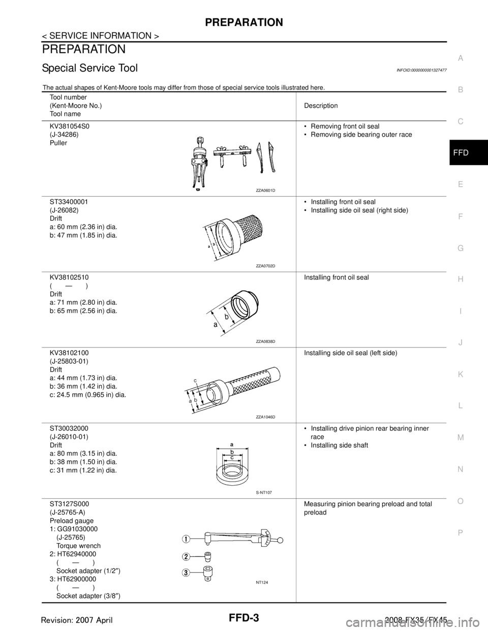
Special Service ToolINFOID:0000000001327477
The actual shapes of Kent-Moore t ools may differ from those of special service tools illustrated here.
Tool number
(Kent-Moore No.)
Tool name Description
KV381054S0
(J-34286)
Puller Removing front oil seal
Removing side bearing outer race
ST33400001
(J-26082)
Drift
a: 60 mm (2.36 in) dia.
b: 47 mm (1.85 in) dia. Installing front oil seal
Installing side oil seal (right side)
KV38102510
(—)
Drift
a: 71 mm (2.80 in) dia.
b: 65 mm (2.56 in) dia. Installing front oil seal
KV38102100
(J-25803-01)
Drift
a: 44 mm (1.73 in) dia.
b: 36 mm (1.42 in) dia.
c: 24.5 mm (0.965 in) dia. Installing side oil seal (left side)
ST30032000
(J-26010-01)
Drift
a: 80 mm (3.15 in) dia.
b: 38 mm (1.50 in) dia.
c: 31 mm (1.22 in) dia. Installing drive pinion rear bearing inner
race
Installing side shaft
ST3127S000
(J-25765-A)
Preload gauge
1: GG91030000 (J-25765)
Torque wrench
2: HT62940000 (—)
Socket adapter (1/2 ″)
3: HT62900000 (—)
Socket adapter (3/8 ″) Measuring pinion bearing preload and total
preload
ZZA0601D
ZZA0702D
ZZA0838D
ZZA1046D
S-NT107
NT124
3AA93ABC3ACD3AC03ACA3AC03AC63AC53A913A773A893A873A873A8E3A773A983AC73AC93AC03AC3
3A893A873A873A8F3A773A9D3AAF3A8A3A8C3A863A9D3AAF3A8B3A8C
Page 2795 of 3924
FFD-4
< SERVICE INFORMATION >
PREPARATION
K V 1 0 1111 0 0
(J-37228)
Seal cutterRemoving carrier cover
ST3306S001
(J-22888-D)
Differential side bearing puller set
1: ST33051001 (J-22888-20)
Puller
2: ST33061000
(J-8107-2)
Base
a: 28.5 mm (1.122 in) dia.
b: 38 mm (1.50 in) dia. Removing and installing side bearing inner
race
ST30031000
(J-22912-01)
Replacer Removing pinion rear bearing inner race
KV31103000
(J-38982)
Drift
a: 49 mm (1.93 in) dia.
b: 70 mm (2.76 in) dia. Installing side bearing outer race
ST30611000
(J-25742-1)
Drift bar Installing side bearing outer race (Use with
KV31103000)
ST37820000
(—)
Drift
a: 39 mm (1.54 in) dia.
b: 72 mm (2.83 in) dia. Installing drive pinion front and rear bearing
outer race
Tool number
(Kent-Moore No.)
Tool name
Description
S-NT046
NT072
ZZA0700D
ZZA1113D
S-NT090
ZZA0836D
3AA93ABC3ACD3AC03ACA3AC03AC63AC53A913A773A893A873A873A8E3A773A983AC73AC93AC03AC3
3A893A873A873A8F3A773A9D3AAF3A8A3A8C3A863A9D3AAF3A8B3A8C
Page 2796 of 3924
PREPARATIONFFD-5
< SERVICE INFORMATION >
CEF
G H
I
J
K L
M A
B
FFD
N
O P
Commercial Service ToolINFOID:0000000001327478
ST33230000
(J-25805-01)
Drift
a: 51 mm (2.01 in) dia.
b: 41 mm (1.61 in) dia.
c: 28.5 mm (1.122 in) dia. Installing side bearing inner race
KV38100200
(—)
Drift
a: 65 mm (2.56 in) dia.
b: 49 mm (1.93 in) dia. Installing side shaft oil seal
(J-8129)
Spring gauge Measuring turning torque
Tool number
(Kent-Moore No.)
Tool name
Description
ZZA1046D
ZZA1143D
NT127
Tool name
Description
Flange wrench Removing and installing drive pinion lock nut
Spacer
a: 60 mm (2.36 in) dia.
b: 36 mm (1.42 in) dia.
c: 30 mm (1.18 in) Installing pinion front bearing inner race
Power tool Loosening bolts and nuts
NT771
ZZA1133D
PBIC0190E
3AA93ABC3ACD3AC03ACA3AC03AC63AC53A913A773A893A873A873A8E3A773A983AC73AC93AC03AC3
3A893A873A873A8F3A773A9D3AAF3A8A3A8C3A863A9D3AAF3A8B3A8C