2008 INFINITI FX35 turn signal
[x] Cancel search: turn signalPage 1210 of 3924
DI-84
< SERVICE INFORMATION >
LANE DEPARTURE WARNING SYSTEM
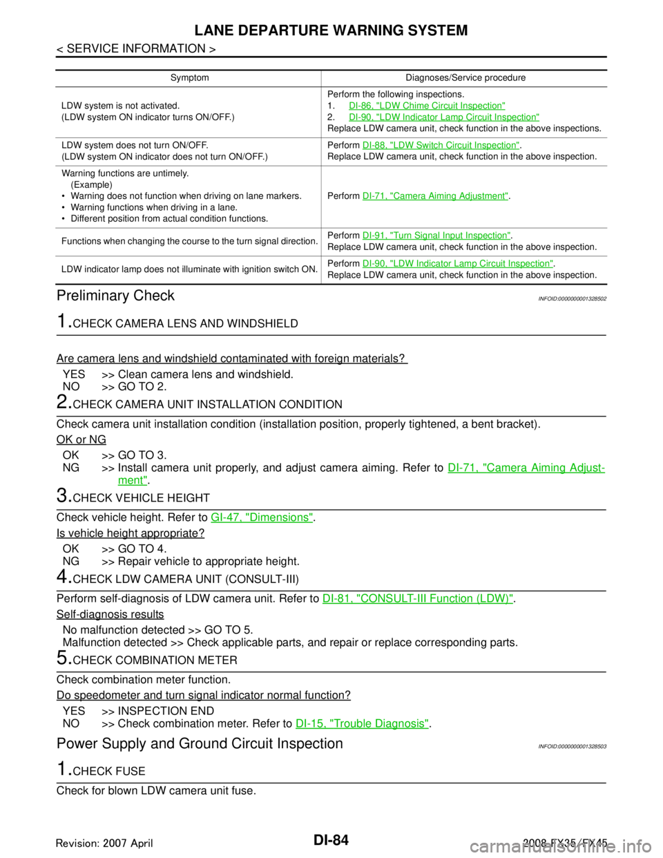
Preliminary Check
INFOID:0000000001328502
1.CHECK CAMERA LENS AND WINDSHIELD
Are camera lens and windshield contaminated with foreign materials?
YES >> Clean camera lens and windshield.
NO >> GO TO 2.
2.CHECK CAMERA UNIT IN STALLATION CONDITION
Check camera unit installation condition (installat ion position, properly tightened, a bent bracket).
OK or NG
OK >> GO TO 3.
NG >> Install camera unit properly, and adjust camera aiming. Refer to DI-71, "
Camera Aiming Adjust-
ment".
3.CHECK VEHICLE HEIGHT
Check vehicle height. Refer to GI-47, "
Dimensions".
Is vehicle height appropriate?
OK >> GO TO 4.
NG >> Repair vehicle to appropriate height.
4.CHECK LDW CAMERA UNIT (CONSULT-III)
Perform self-diagnosis of LDW camera unit. Refer to DI-81, "
CONSULT-III Function (LDW)".
Self
-diagnosis results
No malfunction detected >> GO TO 5.
Malfunction detected >> Check applicable parts, and repair or replace corresponding parts.
5.CHECK COMBINATION METER
Check combination meter function.
Do speedometer and turn signal indicator normal function?
YES >> INSPECTION END
NO >> Check combination meter. Refer to DI-15, "
Trouble Diagnosis".
Power Supply and Ground Circuit InspectionINFOID:0000000001328503
1.CHECK FUSE
Check for blown LDW camera unit fuse.
Symptom Diagnoses/Service procedure
LDW system is not activated.
(LDW system ON indicator turns ON/OFF.) Perform the following inspections.
1.
DI-86, "
LDW Chime Circuit Inspection"
2.DI-90, "LDW Indicator Lamp Circuit Inspection"
Replace LDW camera unit, check function in the above inspections.
LDW system does not turn ON/OFF.
(LDW system ON indicator does not turn ON/OFF.) Perform
DI-88, "
LDW Switch Circuit Inspection".
Replace LDW camera unit, check function in the above inspection.
Warning functions are untimely. (Example)
Warning does not function when driving on lane markers.
Warning functions when driving in a lane.
Different position from actual condition functions. Perform
DI-71, "
Camera Aiming Adjustment".
Functions when changing the course to the turn signal direction. Perform
DI-91, "
Turn Signal Input Inspection".
Replace LDW camera unit, check function in the above inspection.
LDW indicator lamp does not illuminate with ignition switch ON. Perform
DI-90, "
LDW Indicator Lamp Circuit Inspection".
Replace LDW camera unit, check function in the above inspection.
3AA93ABC3ACD3AC03ACA3AC03AC63AC53A913A773A893A873A873A8E3A773A983AC73AC93AC03AC3
3A893A873A873A8F3A773A9D3AAF3A8A3A8C3A863A9D3AAF3A8B3A8C
Page 1213 of 3924
LANE DEPARTURE WARNING SYSTEMDI-87
< SERVICE INFORMATION >
C
DE
F
G H
I
J
L
M A
B
DI
N
O P
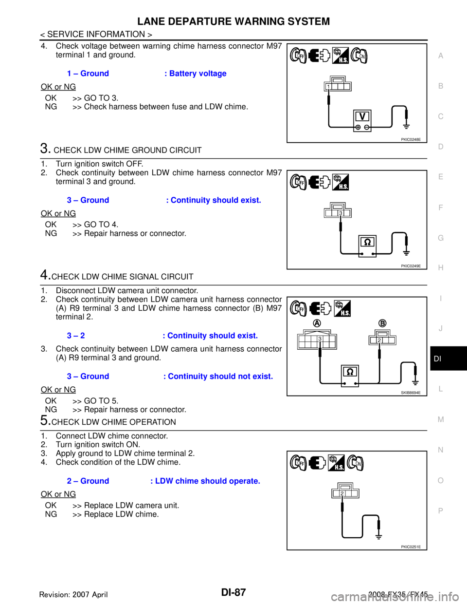
4. Check voltage between warning chime harness connector M97 terminal 1 and ground.
OK or NG
OK >> GO TO 3.
NG >> Check harness between fuse and LDW chime.
3. CHECK LDW CHIME GROUND CIRCUIT
1. Turn ignition switch OFF.
2. Check continuity between LDW chime harness connector M97 terminal 3 and ground.
OK or NG
OK >> GO TO 4.
NG >> Repair harness or connector.
4.CHECK LDW CHIME SIGNAL CIRCUIT
1. Disconnect LDW camera unit connector.
2. Check continuity between LDW camera unit harness connector (A) R9 terminal 3 and LDW chime harness connector (B) M97
terminal 2.
3. Check continuity between LDW camera unit harness connector (A) R9 terminal 3 and ground.
OK or NG
OK >> GO TO 5.
NG >> Repair harness or connector.
5.CHECK LDW CHIME OPERATION
1. Connect LDW chime connector.
2. Turn ignition switch ON.
3. Apply ground to LDW chime terminal 2.
4. Check condition of the LDW chime.
OK or NG
OK >> Replace LDW camera unit.
NG >> Replace LDW chime. 1 – Ground : Battery voltage
PKIC0248E
3 – Ground : Continuity should exist.
PKIC0249E
3 – 2 : Continui
ty should exist.
3 – Ground : Continuity should not exist.
SKIB8694E
2 – Ground : LDW chime should operate.
PKIC0251E
3AA93ABC3ACD3AC03ACA3AC03AC63AC53A913A773A893A873A873A8E3A773A983AC73AC93AC03AC3
3A893A873A873A8F3A773A9D3AAF3A8A3A8C3A863A9D3AAF3A8B3A8C
Page 1214 of 3924
DI-88
< SERVICE INFORMATION >
LANE DEPARTURE WARNING SYSTEM
LDW Switch Circuit Inspection
INFOID:0000000001328511
1.CHECK OPERATION OF LDW SYSTEM ON INDICATOR
1. Turn ignition switch ON.
2. Check LDW system ON indicator operation when LDW switch is ON/OFF.
OK or NG
OK >> INSPECTION END
NG >> GO TO 2.
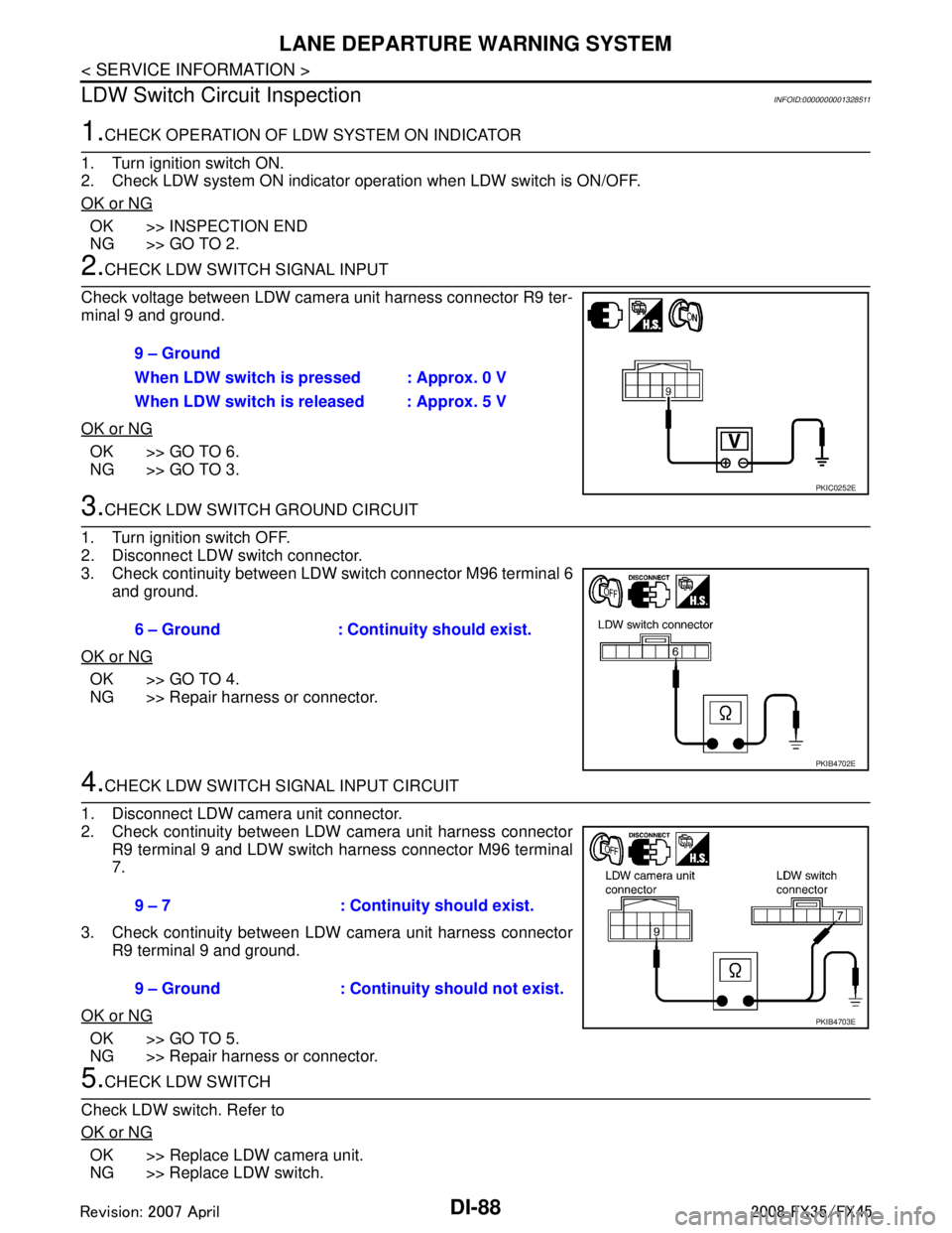
2.CHECK LDW SWITCH SIGNAL INPUT
Check voltage between LDW camera unit harness connector R9 ter-
minal 9 and ground.
OK or NG
OK >> GO TO 6.
NG >> GO TO 3.
3.CHECK LDW SWITCH GROUND CIRCUIT
1. Turn ignition switch OFF.
2. Disconnect LDW switch connector.
3. Check continuity between LDW switch connector M96 terminal 6 and ground.
OK or NG
OK >> GO TO 4.
NG >> Repair harness or connector.
4.CHECK LDW SWITCH SIGNAL INPUT CIRCUIT
1. Disconnect LDW camera unit connector.
2. Check continuity between LDW camera unit harness connector R9 terminal 9 and LDW switch harness connector M96 terminal
7.
3. Check continuity between LDW camera unit harness connector R9 terminal 9 and ground.
OK or NG
OK >> GO TO 5.
NG >> Repair harness or connector.
5.CHECK LDW SWITCH
Check LDW switch. Refer to
OK or NG
OK >> Replace LDW camera unit.
NG >> Replace LDW switch. 9 – Ground
When LDW switch is pressed : Approx. 0 V
When LDW switch is released : Approx. 5 V
PKIC0252E
6 – Ground : Continuity should exist.
PKIB4702E
9 – 7 : Continuity should exist.
9 – Ground : Continuity should not exist.
PKIB4703E
3AA93ABC3ACD3AC03ACA3AC03AC63AC53A913A773A893A873A873A8E3A773A983AC73AC93AC03AC3
3A893A873A873A8F3A773A9D3AAF3A8A3A8C3A863A9D3AAF3A8B3A8C
Page 1215 of 3924

LANE DEPARTURE WARNING SYSTEMDI-89
< SERVICE INFORMATION >
C
DE
F
G H
I
J
L
M A
B
DI
N
O P
6.CHECK OPERATION OF LDW SYSTEM ON INDICATOR
Check LDW system ON indicator oper ation “SYSTEM ON LAMP DRIVE” in “Active Test” mode with CON-
SULT-III.
NOTE:
Perform “SYSTEM ON LAMP DRIVE” when LDW system ON indicator turns OFF.
OK or NG
OK >> Replace LDW camera unit.
NG >> GO TO 7.
7.CHECK LDW SYSTEM ON INDICATOR POWER SUPPLY CIRCUIT
1. Turn ignition switch OFF.
2. Disconnect LDW switch connector.
3. Turn ignition switch ON.
4. Check voltage between LDW switch harness connector M96 ter- minal 3 and ground.
OK or NG
OK >> GO TO 8.
NG >> Check harness between fuse and LDW switch.
8.CHECK LDW SYSTEM ON INDICATOR SIGNAL CIRCUIT
1. Disconnect LDW camera unit connector.
2. Check continuity between LDW camera unit harness connector R9 terminal 4 and LDW switch harness connector M96 terminal
2.
3. Check continuity between LDW camera unit harness connector R9 terminal 4 and ground.
OK or NG
OK >> GO TO 9.
NG >> Repair harness or connector.
9.CHECK LDW SYSTEM ON INDICATOR
1. Connect LDW switch connector.
2. Turn ignition switch ON. “SYSTEM ON LAMP DRIVE”
Select “On” : LDW system ON
indicator illuminates.
Select “Off” : LDW system ON indicator turns OFF.
3 – Ground : Battery voltage
PKIB4705E
4 – 2 : Continuity should exist.
4 – Ground : Continuity should not exist.
PKIB4706E
3AA93ABC3ACD3AC03ACA3AC03AC63AC53A913A773A893A873A873A8E3A773A983AC73AC93AC03AC3
3A893A873A873A8F3A773A9D3AAF3A8A3A8C3A863A9D3AAF3A8B3A8C
Page 1216 of 3924
DI-90
< SERVICE INFORMATION >
LANE DEPARTURE WARNING SYSTEM
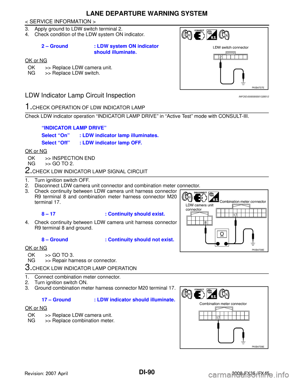
3. Apply ground to LDW switch terminal 2.
4. Check condition of the LDW system ON indicator.
OK or NG
OK >> Replace LDW camera unit.
NG >> Replace LDW switch.
LDW Indicator Lamp Circuit InspectionINFOID:0000000001328512
1.CHECK OPERATION OF LDW INDICATOR LAMP
Check LDW indicator operation “INDICATOR LAMP DR IVE” in “Active Test” mode with CONSULT-III.
OK or NG
OK >> INSPECTION END
NG >> GO TO 2.
2.CHECK LDW INDICATOR LAMP SIGNAL CIRCUIT
1. Turn ignition switch OFF.
2. Disconnect LDW camera unit connector and combination meter connector.
3. Check continuity between LDW camera unit harness connector R9 terminal 8 and combination meter harness connector M20
terminal 17.
4. Check continuity between LDW camera unit harness connector R9 terminal 8 and ground.
OK or NG
OK >> GO TO 3.
NG >> Repair harness or connector.
3.CHECK LDW INDICATOR LAMP OPERATION
1. Connect combination meter connector.
2. Turn ignition switch ON.
3. Ground combination meter harness connector M20 terminal 17.
OK or NG
OK >> Replace LDW camera unit.
NG >> Replace combination meter. 2 – Ground : LDW system ON indicator
should illuminate.
PKIB4707E
“INDICATOR LAMP DRIVE”
Select “On” : LDW indicator lamp illuminates.
Select “Off” : LDW indicator lamp OFF.
8 – 17 : Continuity should exist.
8 – Ground : Continuity should not exist.
PKIB4708E
17 – Ground : LDW indicator should illuminate.
PKIB4709E
3AA93ABC3ACD3AC03ACA3AC03AC63AC53A913A773A893A873A873A8E3A773A983AC73AC93AC03AC3
3A893A873A873A8F3A773A9D3AAF3A8A3A8C3A863A9D3AAF3A8B3A8C
Page 1217 of 3924
LANE DEPARTURE WARNING SYSTEMDI-91
< SERVICE INFORMATION >
C
DE
F
G H
I
J
L
M A
B
DI
N
O P
Turn Signal Input InspectionINFOID:0000000001328513
1.CHECK TURN SIGNAL INPUT
Check turn signal input “TURN SIGNAL” in “Data Monitor” mode with CONSULT-III.
OK or NG
OK >> INSPECTION END
NG >> Check turn signal and hazard warning lamps system, and repair or replace corresponding parts. Refer to LT-88, "
How to Proceed with Trouble Diagnosis".
Electrical Component InspectionINFOID:0000000001328514
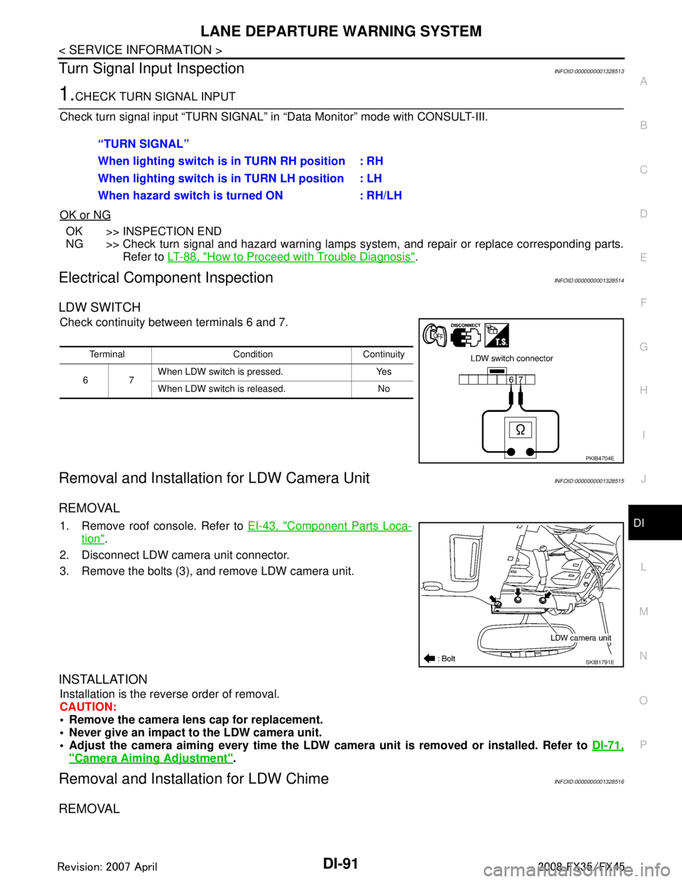
LDW SWITCH
Check continuity between terminals 6 and 7.
Removal and Installation for LDW Camera UnitINFOID:0000000001328515
REMOVAL
1. Remove roof console. Refer to EI-43, "Component Parts Loca-
tion".
2. Disconnect LDW camera unit connector.
3. Remove the bolts (3), and remove LDW camera unit.
INSTALLATION
Installation is the reverse order of removal.
CAUTION:
Remove the camera lens cap for replacement.
Never give an impact to the LDW camera unit.
Adjust the camera aiming every time the LDW camer a unit is removed or installed. Refer to DI-71,
"Camera Aiming Adjustment".
Removal and Installation for LDW ChimeINFOID:0000000001328516
REMOVAL
“TURN SIGNAL”
When lighting switch is in TURN RH position : RH
When lighting switch is in TURN LH position : LH
When hazard switch is turned ON : RH/LH
Terminal Condition Continuity
67 When LDW switch is pressed. Yes
When LDW switch is released. No
PKIB4704E
SKIB1791E
3AA93ABC3ACD3AC03ACA3AC03AC63AC53A913A773A893A873A873A8E3A773A983AC73AC93AC03AC3
3A893A873A873A8F3A773A9D3AAF3A8A3A8C3A863A9D3AAF3A8B3A8C
Page 1235 of 3924
REAR VIEW MONITORDI-109
< SERVICE INFORMATION >
C
DE
F
G H
I
J
L
M A
B
DI
N
O P
YES >> GO TO 2.
NO >> Check back-up lamp system. Refer to LT-116, "
Wiring Diagram - BACK/L -" in LT section.
2.CHECK REVERSE POSITION INPUT SIGNAL
With CONSULT-III
1. Select “Data Monitor” of “REARVIEW CAMERA”.
2. Operate ignition switch with “R POSI SIG” of “Data Monitor” and check operate status.
Without CONSULT-III
1. Turn ignition switch OFF.
2. Disconnect rear view camera control unit connector.
3. Turn ignition switch ON.
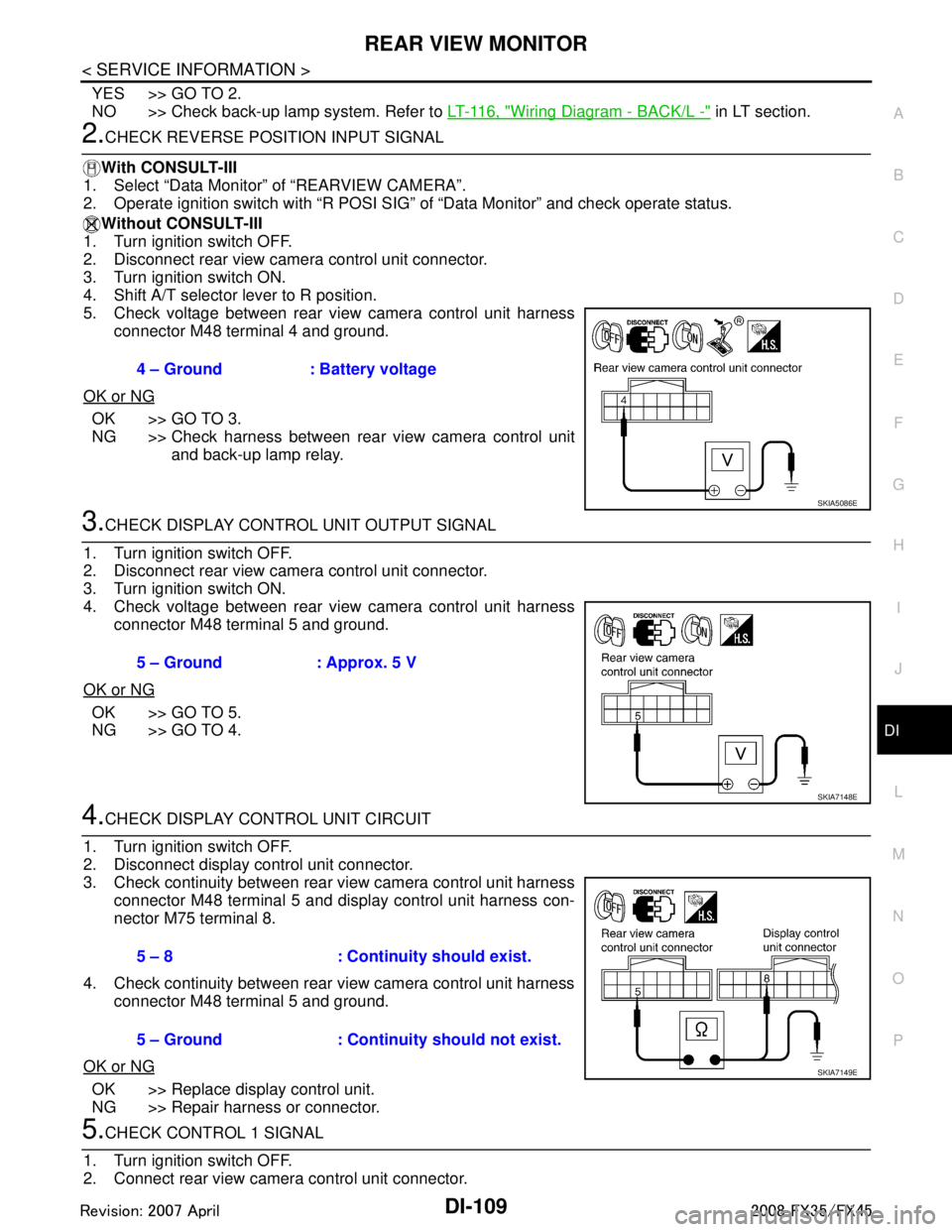
4. Shift A/T selector lever to R position.
5. Check voltage between rear view camera control unit harness
connector M48 terminal 4 and ground.
OK or NG
OK >> GO TO 3.
NG >> Check harness between rear view camera control unit and back-up lamp relay.
3.CHECK DISPLAY CONTROL UNIT OUTPUT SIGNAL
1. Turn ignition switch OFF.
2. Disconnect rear view camera control unit connector.
3. Turn ignition switch ON.
4. Check voltage between rear view camera control unit harness connector M48 terminal 5 and ground.
OK or NG
OK >> GO TO 5.
NG >> GO TO 4.
4.CHECK DISPLAY CO NTROL UNIT CIRCUIT
1. Turn ignition switch OFF.
2. Disconnect display control unit connector.
3. Check continuity between rear view camera control unit harness connector M48 terminal 5 and display control unit harness con-
nector M75 terminal 8.
4. Check continuity between rear view camera control unit harness connector M48 terminal 5 and ground.
OK or NG
OK >> Replace display control unit.
NG >> Repair harness or connector.
5.CHECK CONTROL 1 SIGNAL
1. Turn ignition switch OFF.
2. Connect rear view camera control unit connector. 4 – Ground : Battery voltage
SKIA5086E
5 – Ground : Approx. 5 V
SKIA7148E
5 – 8 : Continuity should exist.
5 – Ground : Continuity should not exist.
SKIA7149E
3AA93ABC3ACD3AC03ACA3AC03AC63AC53A913A773A893A873A873A8E3A773A983AC73AC93AC03AC3
3A893A873A873A8F3A773A9D3AAF3A8A3A8C3A863A9D3AAF3A8B3A8C
Page 1237 of 3924
REAR VIEW MONITORDI-111
< SERVICE INFORMATION >
C
DE
F
G H
I
J
L
M A
B
DI
N
O P
NG >> Repair or replace power supply and ground circuit.
9.CHECK REAR VIEW CAMERA CONTROL UNIT OUTPUT SIGNAL
1. Turn ignition switch OFF.
2. Connect rear view camera control unit connector.
3. Turn ignition switch ON.
4. Shift A/T selector lever to R position.
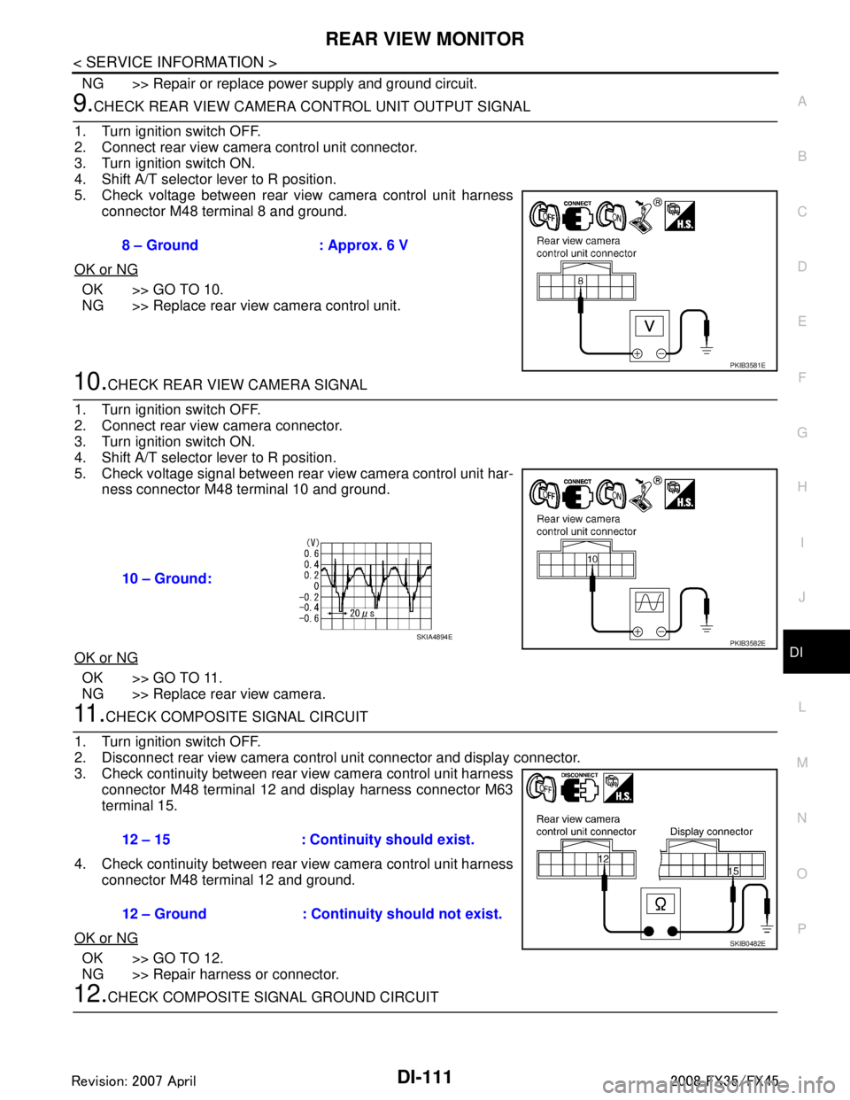
5. Check voltage between rear view camera control unit harness connector M48 terminal 8 and ground.
OK or NG
OK >> GO TO 10.
NG >> Replace rear view camera control unit.
10.CHECK REAR VIEW CAMERA SIGNAL
1. Turn ignition switch OFF.
2. Connect rear view camera connector.
3. Turn ignition switch ON.
4. Shift A/T selector lever to R position.
5. Check voltage signal between rear view camera control unit har- ness connector M48 terminal 10 and ground.
OK or NG
OK >> GO TO 11.
NG >> Replace rear view camera.
11 .CHECK COMPOSITE SIGNAL CIRCUIT
1. Turn ignition switch OFF.
2. Disconnect rear view camera control unit connector and display connector.
3. Check continuity between rear view camera control unit harness connector M48 terminal 12 and display harness connector M63
terminal 15.
4. Check continuity between rear view camera control unit harness connector M48 terminal 12 and ground.
OK or NG
OK >> GO TO 12.
NG >> Repair harness or connector.
12.CHECK COMPOSITE SI GNAL GROUND CIRCUIT
8 – Ground : Approx. 6 V
PKIB3581E
10 – Ground:
PKIB3582ESKIA4894E
12 – 15 : Continuity should exist.
12 – Ground : Continuity should not exist.
SKIB0482E
3AA93ABC3ACD3AC03ACA3AC03AC63AC53A913A773A893A873A873A8E3A773A983AC73AC93AC03AC3
3A893A873A873A8F3A773A9D3AAF3A8A3A8C3A863A9D3AAF3A8B3A8C