2008 INFINITI FX35 air condition
[x] Cancel search: air conditionPage 1152 of 3924

DI-26
< SERVICE INFORMATION >
UNIFIED METER AND A/C AMP
UNIFIED METER AND A/C AMP
System DescriptionINFOID:0000000001328456
For the unified meter and A/C amp., the signal required for controlling the combination meter are integrated
in the A/C auto amp.
The unified meter and A/C amp. corresponds to a CONS ULT-III function (self-diagnosis results, CAN diag-
nosis support monitor, data monitor).
COMBINATION METER CONTROL FUNCTION
Unified meter and A/C amp. receives necessary information for combination meter from each unit by CAN communication.
Unified meter and A/C amp. transmits a signals with communication line (TX, RX) between unified meter and A/C amp. and combination meter.
Input/output signals between unified meter and A/C amp. and combination meter.
NOTE:
Combination meter performs fail-safe operation when unified meter and A/C amp. communication is malfunctioning. Refer to DI-5, "
Sys-
tem Description".
A/C AUTO AMP. FUNCTION
Unified meter and A/C amp. controls each operation for A/C auto amp. Regarding A/C control, refer to AT C -
24, "Description of Air Conditioner LAN Control System" in ATC section.
OTHER FUNCTIONS
Drive Computer Function
The signals required for the distance to empty (DTE) display are centralized in the unified meter and A/C
amp., converted into data, and transmitted to the disp lay unit (without NAVI) and display control unit (with
NAVI) using CAN communication.
Signal Buffer Function
Unified meter and A/C amp. transmits each signal to other units with CAN communication.
Unit Input Output
Unified meter and A/C amp. Seat belt buckle switch signal (Driver's side)
Parking brake signal
Illumination control nighttime required signal
Refuel status signal
Low-fuel warning lamp condition signal
Combination meter receive error signal
Delivery destination data signal
Combination meter specifications signal Vehicle speed signal (8-pulse)
Engine speed signal
Engine coolant temperature signal
Fuel level sensor signal (resistance value)
Malfunction indicator lamp signal
ABS warning lamp signal
Low tire pressure warning lamp signal
Run-flat tire wa
rning lamp signal
Brake warning lamp signal
A/T CHECK warning lamp signal
ICC warning lamp signal
Oil pressure switch signal
Door switch signal
AWD warning lamp signal
Key warning lamp signal
VDC OFF indicator lamp signal
SLIP indicator lamp signal
CRUISE indicator lamp signal
SET indicator lamp signal
High beam request signal
Turn indicator signal
Snow mode switch signal
ICC system display signal
Shift position indicator signal
Manual mode indicator signal
Manual mode gear position signal
CAN communication condition signal of A/T
Position lights request signal
Buzzer output signal
3AA93ABC3ACD3AC03ACA3AC03AC63AC53A913A773A893A873A873A8E3A773A983AC73AC93AC03AC3
3A893A873A873A8F3A773A9D3AAF3A8A3A8C3A863A9D3AAF3A8B3A8C
Page 1154 of 3924

DI-28
< SERVICE INFORMATION >
UNIFIED METER AND A/C AMP
SELF-DIAG RESULTS
Display Item List
NOTE:
“TIME” means the following.
0: Means detected malfunction at present. (From malfunction detection to turning ignition switch OFF)
1 - 63: Means detected malfunction in the past . (Displays the number of ignition switch OFF → ON after
detecting malfunction. “Self Diagnostic Result” is erased when exceeding “63”.)
DATA MONITOR
Display Item List
X: Applicable
System Diagnosis mode Description
METER A/C AMP Self Diagnostic Result
Unified meter and A/C amp. checks the conditions and displays
memorized error.
CAN DIAG SUPPORT MNTR The results of transmit/receive diagnosis of CAN communication
can be read.
Data Monitor Displays unified meter and A/C amp. input data in real time.
Display item [Code] Malfunction is detected when... Reference
page
CAN COMM CIRC [U1000] When unified meter and A/C amp. is not transmitting or receiving CAN communication
signal for 2 seconds or more. DI-30
METER COMM CIRC [B2202]Malfunction is detected in communication of between combination meter and unified
meter and A/C amp.
DI-30
VEHICLE SPEED CIRC [B2205]When an erroneous speed signal is input for 1 second.
NOTE:
Even when there is no malfunction on speed signal system, malfunction may be misin-
terpreted when battery has low voltage (when maintaining 7 - 8 V for about 2 seconds). DI-32
Display item [Unit]
MAIN
SIGNALS SELECTION
FROM MENU Contents
SPEED METER [km/h] or [mph] X X Displays the value of vehicle speed signal, which is input from
ABS actuator and electric unit (control unit).
SPEED OUTPUT [km/h] or [mph] X X Displays the value of vehicle speed signal, which is transmitted
to each unit with CAN communication.
TACHO METER [rpm] X X Displays the value of engine speed signal, which is input from
ECM.
W TEMP METER [ °C] or [ °F] X X Displays the value of engine coolant temperature signal, which is
input from ECM.
FUEL METER [lit.] X X Displays the value, which processes a resistance signal from fuel
gauge.
DISTANCE [km] or [mile] X X Displays the value, which is calculated by vehicle speed signal
from ABS actuator and electric unit
(control unit), fuel gauge and
fuel consumption from ECM.
FUEL W/L [On/Off] X X Indicates [On/Off] condition of low-fuel warning lamp.
MIL [On/Off] X Indicates [On/Off] condition of malfunction indicator lamp.
AIR PRES W/L [On/Off] X Indicates [On/Off] condition of low tire pressure warning lamp.
SEAT BELT W/L [On/Off]
*1X Indicates [On/Off] condition of seat belt warning lamp.
BUZZER [On/Off] X X Indicates [On/Off] condition of buzzer.
DOOR W/L [On/Off] X Indicates [On/Off] condition of door warning lamp.
HI-BEAM IND [On/Off] X Indicates [On/Off] condition of high beam indicator.
TURN IND [On/Off] X Indicates [On/Off] condition of turn indicator.
3AA93ABC3ACD3AC03ACA3AC03AC63AC53A913A773A893A873A873A8E3A773A983AC73AC93AC03AC3
3A893A873A873A8F3A773A9D3AAF3A8A3A8C3A863A9D3AAF3A8B3A8C
Page 1172 of 3924
DI-46
< SERVICE INFORMATION >
WARNING LAMPS
5.CHECK IPDM E/R (CONSULT-III)
Perform self-diagnosis of IPDM E/R. Refer to PG-18, "
CONSULT-III Function (IPDM E/R)".
Self-diagnosis results
No malfunction detected >> Replace combination meter.
Malfunction detected >> Check applicable parts, and repair or replace corresponding parts.
Component InspectionINFOID:0000000001328469
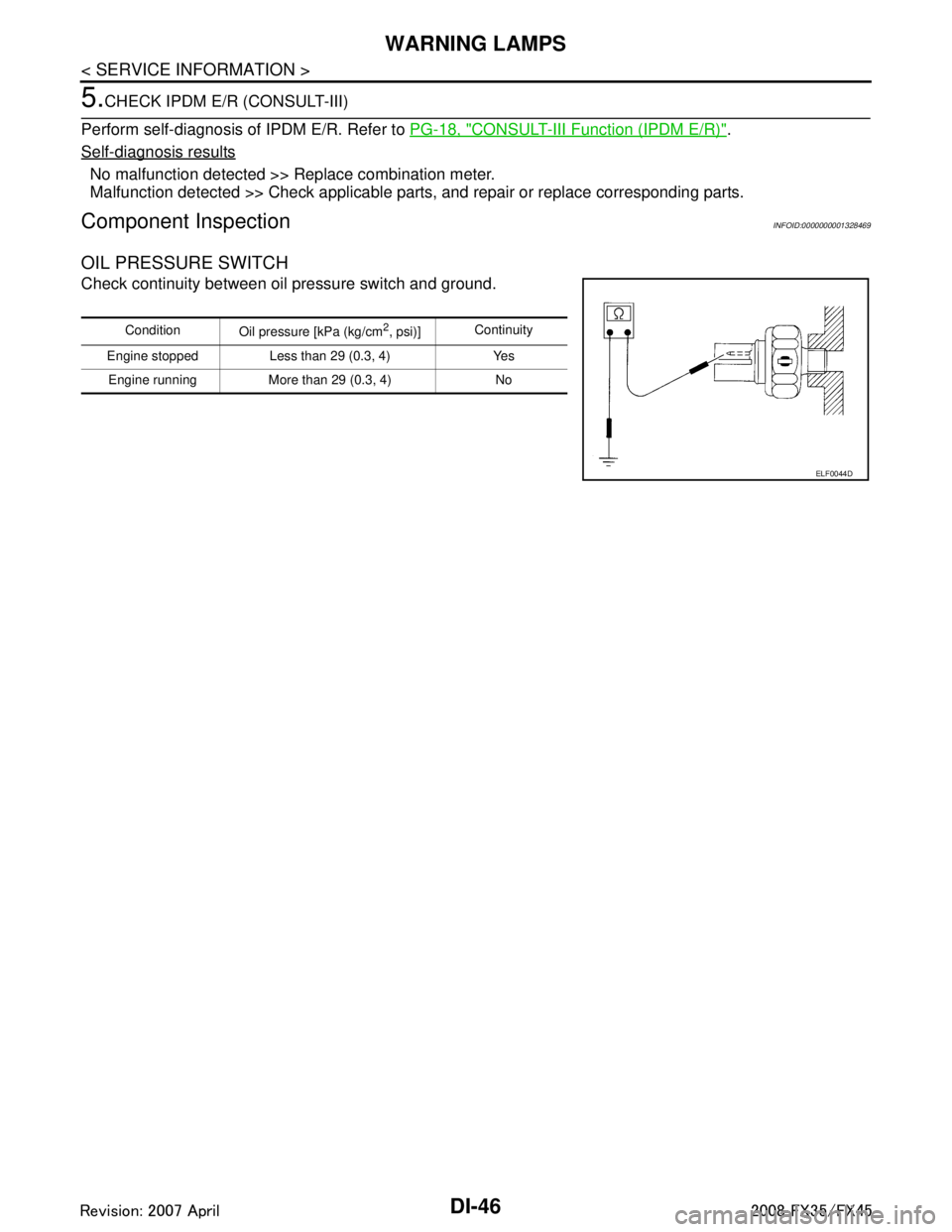
OIL PRESSURE SWITCH
Check continuity between oil pressure switch and ground.
Condition
Oil pressure [kPa (kg/cm2, psi)]Continuity
Engine stopped Less than 29 (0.3, 4) Yes Engine running More than 29 (0.3, 4) No
ELF0044D
3AA93ABC3ACD3AC03ACA3AC03AC63AC53A913A773A893A873A873A8E3A773A983AC73AC93AC03AC3
3A893A873A873A8F3A773A9D3AAF3A8A3A8C3A863A9D3AAF3A8B3A8C
Page 1210 of 3924
DI-84
< SERVICE INFORMATION >
LANE DEPARTURE WARNING SYSTEM
Preliminary Check
INFOID:0000000001328502
1.CHECK CAMERA LENS AND WINDSHIELD
Are camera lens and windshield contaminated with foreign materials?
YES >> Clean camera lens and windshield.
NO >> GO TO 2.
2.CHECK CAMERA UNIT IN STALLATION CONDITION
Check camera unit installation condition (installat ion position, properly tightened, a bent bracket).
OK or NG
OK >> GO TO 3.
NG >> Install camera unit properly, and adjust camera aiming. Refer to DI-71, "
Camera Aiming Adjust-
ment".
3.CHECK VEHICLE HEIGHT
Check vehicle height. Refer to GI-47, "
Dimensions".
Is vehicle height appropriate?
OK >> GO TO 4.
NG >> Repair vehicle to appropriate height.
4.CHECK LDW CAMERA UNIT (CONSULT-III)
Perform self-diagnosis of LDW camera unit. Refer to DI-81, "
CONSULT-III Function (LDW)".
Self
-diagnosis results
No malfunction detected >> GO TO 5.
Malfunction detected >> Check applicable parts, and repair or replace corresponding parts.
5.CHECK COMBINATION METER
Check combination meter function.
Do speedometer and turn signal indicator normal function?
YES >> INSPECTION END
NO >> Check combination meter. Refer to DI-15, "
Trouble Diagnosis".
Power Supply and Ground Circuit InspectionINFOID:0000000001328503
1.CHECK FUSE
Check for blown LDW camera unit fuse.
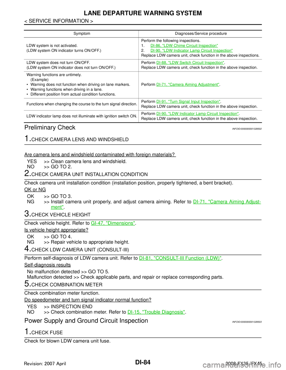
Symptom Diagnoses/Service procedure
LDW system is not activated.
(LDW system ON indicator turns ON/OFF.) Perform the following inspections.
1.
DI-86, "
LDW Chime Circuit Inspection"
2.DI-90, "LDW Indicator Lamp Circuit Inspection"
Replace LDW camera unit, check function in the above inspections.
LDW system does not turn ON/OFF.
(LDW system ON indicator does not turn ON/OFF.) Perform
DI-88, "
LDW Switch Circuit Inspection".
Replace LDW camera unit, check function in the above inspection.
Warning functions are untimely. (Example)
Warning does not function when driving on lane markers.
Warning functions when driving in a lane.
Different position from actual condition functions. Perform
DI-71, "
Camera Aiming Adjustment".
Functions when changing the course to the turn signal direction. Perform
DI-91, "
Turn Signal Input Inspection".
Replace LDW camera unit, check function in the above inspection.
LDW indicator lamp does not illuminate with ignition switch ON. Perform
DI-90, "
LDW Indicator Lamp Circuit Inspection".
Replace LDW camera unit, check function in the above inspection.
3AA93ABC3ACD3AC03ACA3AC03AC63AC53A913A773A893A873A873A8E3A773A983AC73AC93AC03AC3
3A893A873A873A8F3A773A9D3AAF3A8A3A8C3A863A9D3AAF3A8B3A8C
Page 1213 of 3924
LANE DEPARTURE WARNING SYSTEMDI-87
< SERVICE INFORMATION >
C
DE
F
G H
I
J
L
M A
B
DI
N
O P
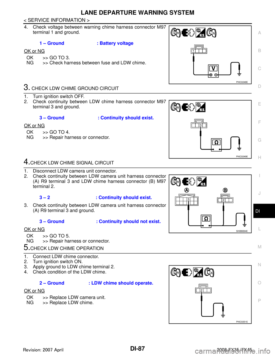
4. Check voltage between warning chime harness connector M97 terminal 1 and ground.
OK or NG
OK >> GO TO 3.
NG >> Check harness between fuse and LDW chime.
3. CHECK LDW CHIME GROUND CIRCUIT
1. Turn ignition switch OFF.
2. Check continuity between LDW chime harness connector M97 terminal 3 and ground.
OK or NG
OK >> GO TO 4.
NG >> Repair harness or connector.
4.CHECK LDW CHIME SIGNAL CIRCUIT
1. Disconnect LDW camera unit connector.
2. Check continuity between LDW camera unit harness connector (A) R9 terminal 3 and LDW chime harness connector (B) M97
terminal 2.
3. Check continuity between LDW camera unit harness connector (A) R9 terminal 3 and ground.
OK or NG
OK >> GO TO 5.
NG >> Repair harness or connector.
5.CHECK LDW CHIME OPERATION
1. Connect LDW chime connector.
2. Turn ignition switch ON.
3. Apply ground to LDW chime terminal 2.
4. Check condition of the LDW chime.
OK or NG
OK >> Replace LDW camera unit.
NG >> Replace LDW chime. 1 – Ground : Battery voltage
PKIC0248E
3 – Ground : Continuity should exist.
PKIC0249E
3 – 2 : Continui
ty should exist.
3 – Ground : Continuity should not exist.
SKIB8694E
2 – Ground : LDW chime should operate.
PKIC0251E
3AA93ABC3ACD3AC03ACA3AC03AC63AC53A913A773A893A873A873A8E3A773A983AC73AC93AC03AC3
3A893A873A873A8F3A773A9D3AAF3A8A3A8C3A863A9D3AAF3A8B3A8C
Page 1216 of 3924
DI-90
< SERVICE INFORMATION >
LANE DEPARTURE WARNING SYSTEM
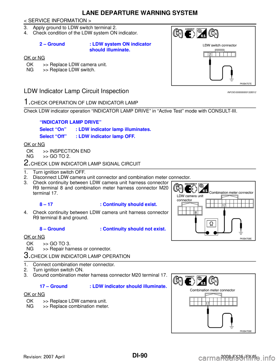
3. Apply ground to LDW switch terminal 2.
4. Check condition of the LDW system ON indicator.
OK or NG
OK >> Replace LDW camera unit.
NG >> Replace LDW switch.
LDW Indicator Lamp Circuit InspectionINFOID:0000000001328512
1.CHECK OPERATION OF LDW INDICATOR LAMP
Check LDW indicator operation “INDICATOR LAMP DR IVE” in “Active Test” mode with CONSULT-III.
OK or NG
OK >> INSPECTION END
NG >> GO TO 2.
2.CHECK LDW INDICATOR LAMP SIGNAL CIRCUIT
1. Turn ignition switch OFF.
2. Disconnect LDW camera unit connector and combination meter connector.
3. Check continuity between LDW camera unit harness connector R9 terminal 8 and combination meter harness connector M20
terminal 17.
4. Check continuity between LDW camera unit harness connector R9 terminal 8 and ground.
OK or NG
OK >> GO TO 3.
NG >> Repair harness or connector.
3.CHECK LDW INDICATOR LAMP OPERATION
1. Connect combination meter connector.
2. Turn ignition switch ON.
3. Ground combination meter harness connector M20 terminal 17.
OK or NG
OK >> Replace LDW camera unit.
NG >> Replace combination meter. 2 – Ground : LDW system ON indicator
should illuminate.
PKIB4707E
“INDICATOR LAMP DRIVE”
Select “On” : LDW indicator lamp illuminates.
Select “Off” : LDW indicator lamp OFF.
8 – 17 : Continuity should exist.
8 – Ground : Continuity should not exist.
PKIB4708E
17 – Ground : LDW indicator should illuminate.
PKIB4709E
3AA93ABC3ACD3AC03ACA3AC03AC63AC53A913A773A893A873A873A8E3A773A983AC73AC93AC03AC3
3A893A873A873A8F3A773A9D3AAF3A8A3A8C3A863A9D3AAF3A8B3A8C
Page 1217 of 3924
LANE DEPARTURE WARNING SYSTEMDI-91
< SERVICE INFORMATION >
C
DE
F
G H
I
J
L
M A
B
DI
N
O P
Turn Signal Input InspectionINFOID:0000000001328513
1.CHECK TURN SIGNAL INPUT
Check turn signal input “TURN SIGNAL” in “Data Monitor” mode with CONSULT-III.
OK or NG
OK >> INSPECTION END
NG >> Check turn signal and hazard warning lamps system, and repair or replace corresponding parts. Refer to LT-88, "
How to Proceed with Trouble Diagnosis".
Electrical Component InspectionINFOID:0000000001328514
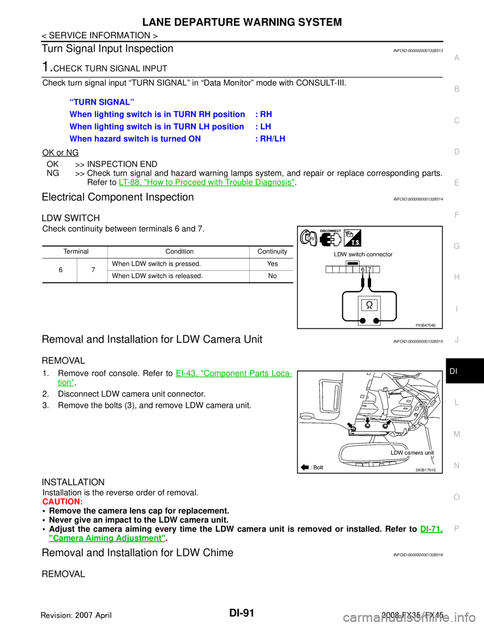
LDW SWITCH
Check continuity between terminals 6 and 7.
Removal and Installation for LDW Camera UnitINFOID:0000000001328515
REMOVAL
1. Remove roof console. Refer to EI-43, "Component Parts Loca-
tion".
2. Disconnect LDW camera unit connector.
3. Remove the bolts (3), and remove LDW camera unit.
INSTALLATION
Installation is the reverse order of removal.
CAUTION:
Remove the camera lens cap for replacement.
Never give an impact to the LDW camera unit.
Adjust the camera aiming every time the LDW camer a unit is removed or installed. Refer to DI-71,
"Camera Aiming Adjustment".
Removal and Installation for LDW ChimeINFOID:0000000001328516
REMOVAL
“TURN SIGNAL”
When lighting switch is in TURN RH position : RH
When lighting switch is in TURN LH position : LH
When hazard switch is turned ON : RH/LH
Terminal Condition Continuity
67 When LDW switch is pressed. Yes
When LDW switch is released. No
PKIB4704E
SKIB1791E
3AA93ABC3ACD3AC03ACA3AC03AC63AC53A913A773A893A873A873A8E3A773A983AC73AC93AC03AC3
3A893A873A873A8F3A773A9D3AAF3A8A3A8C3A863A9D3AAF3A8B3A8C
Page 1222 of 3924

DI-96
< SERVICE INFORMATION >
COMPASS
if an aftermarket (i.e., non original equipment) antenna with a magnetic base is attached to the vehicle. Cali-
brate the mirror compass if the display shows onl y one direction or a limited number of directions.
NOTE:
If “magnetic hats” are used in the dealership for vehicle identification, remove the hat from the vehicle before
performing the following steps. Do NOT put the hat back on the vehicle after the procedure is completed.
Drive the vehicle to an open level area; away from large metallic objects, structures, and overhead power
lines.
Turn off “non-essential” electrical accessories (r ear window defrost, heater/air conditioning, wipers) and
close the doors.
1. Verify the correct compass zone setting for the geographical location. Refer to DI-95, "
Zone Variation Set-
ting Procedure".
2. Press and hold the inside mirror switch for more than 9 seconds.
3. “C” is displayed on the compass display, when calibration starts.
4. Drive slowly [less than 8 km/h (5 mph)] in a circle until the “C / CAL” is replaced with primary headings (N,
NE, E, SE, S, SW, W, or NW).
NOTE:
This will require driving at least 2 complete 360 degree circles; 3 complete circles may be required.
5. The compass calibration procedure is now complete. The compass should operate normally. NOTE:
If at any time the compass continually displays the in correct direction or the reading is erratic or locked,
repeat the calibration procedure.
3AA93ABC3ACD3AC03ACA3AC03AC63AC53A913A773A893A873A873A8E3A773A983AC73AC93AC03AC3
3A893A873A873A8F3A773A9D3AAF3A8A3A8C3A863A9D3AAF3A8B3A8C